Leaderboard


Popular Content
Showing content with the highest reputation on 01/17/21 in all areas
-
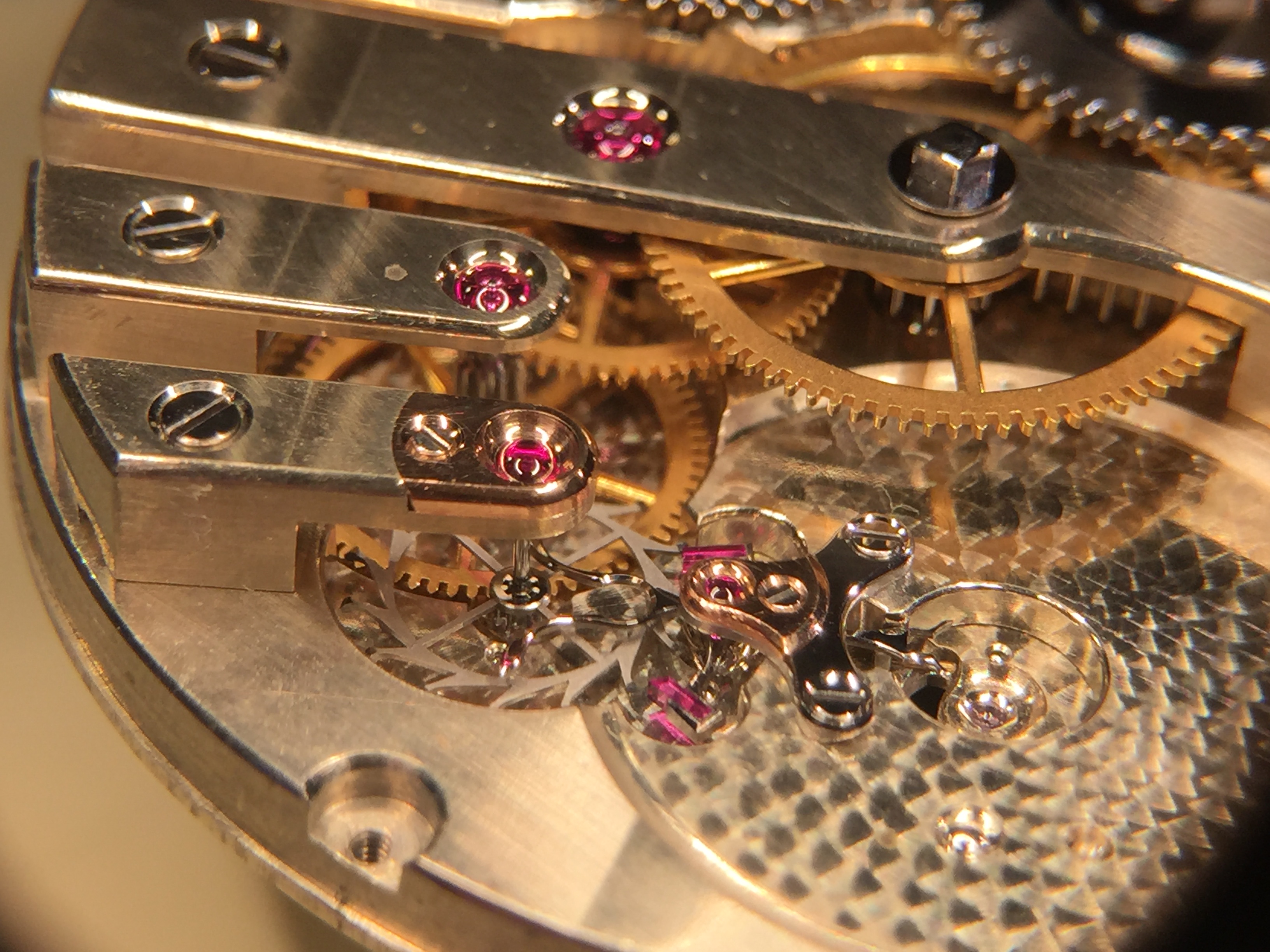
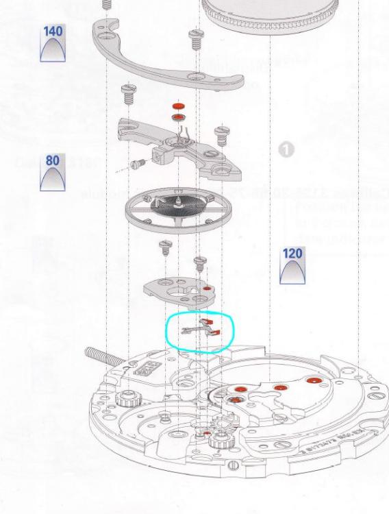
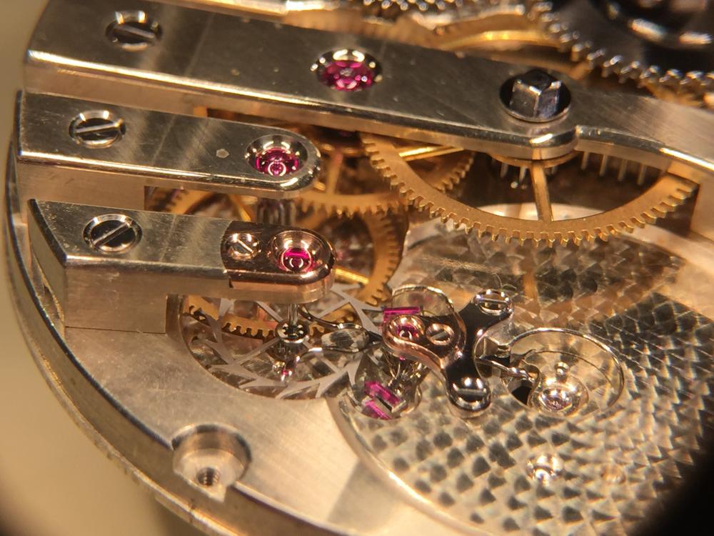
Well, if your watch is in great shape - that's even better. Do not get confused and scared by the diagram above, it's misleading in the sense that you only need to remove 2 F screws (you guess what F stands for, right?) to get a clear view of the pallet fork, and 2 extra screws (also F) to get the pallet fork out. How F complicated is that?2 points
-
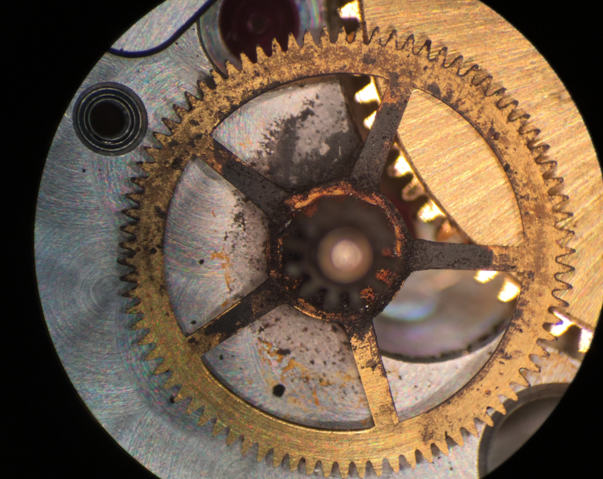
If all wheels turn while winding, then your pallet fork is not doing what it supposed to do. You can see it from the back side - next to the balance wheel.2 points
-
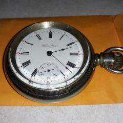
Moser in black & white
 2 points
 -
They're from the same family so that should mean they share the same stem.1 point
-
IBM please be aware if you loose or break any parts genuine Rolex parts are expensive and often very difficult to source. Only attempt this service/repair if you are really confident.1 point
-
Problem is, reputable and accredited watchmakers are likely to decline working on fakes. Unfortunately that is the position many people find themselves with Chinese watches that turns out to be defective before or later.1 point
-
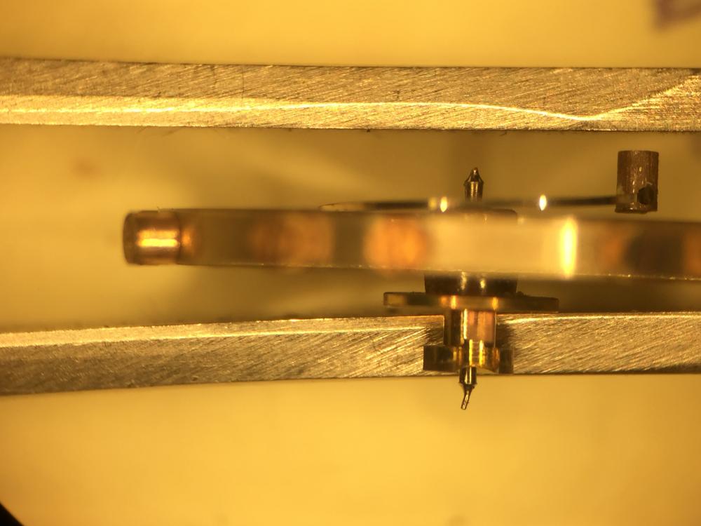
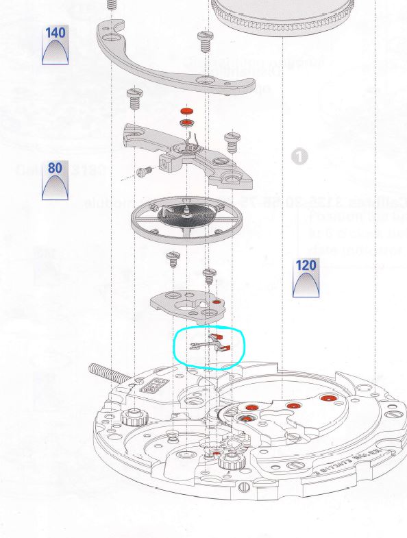
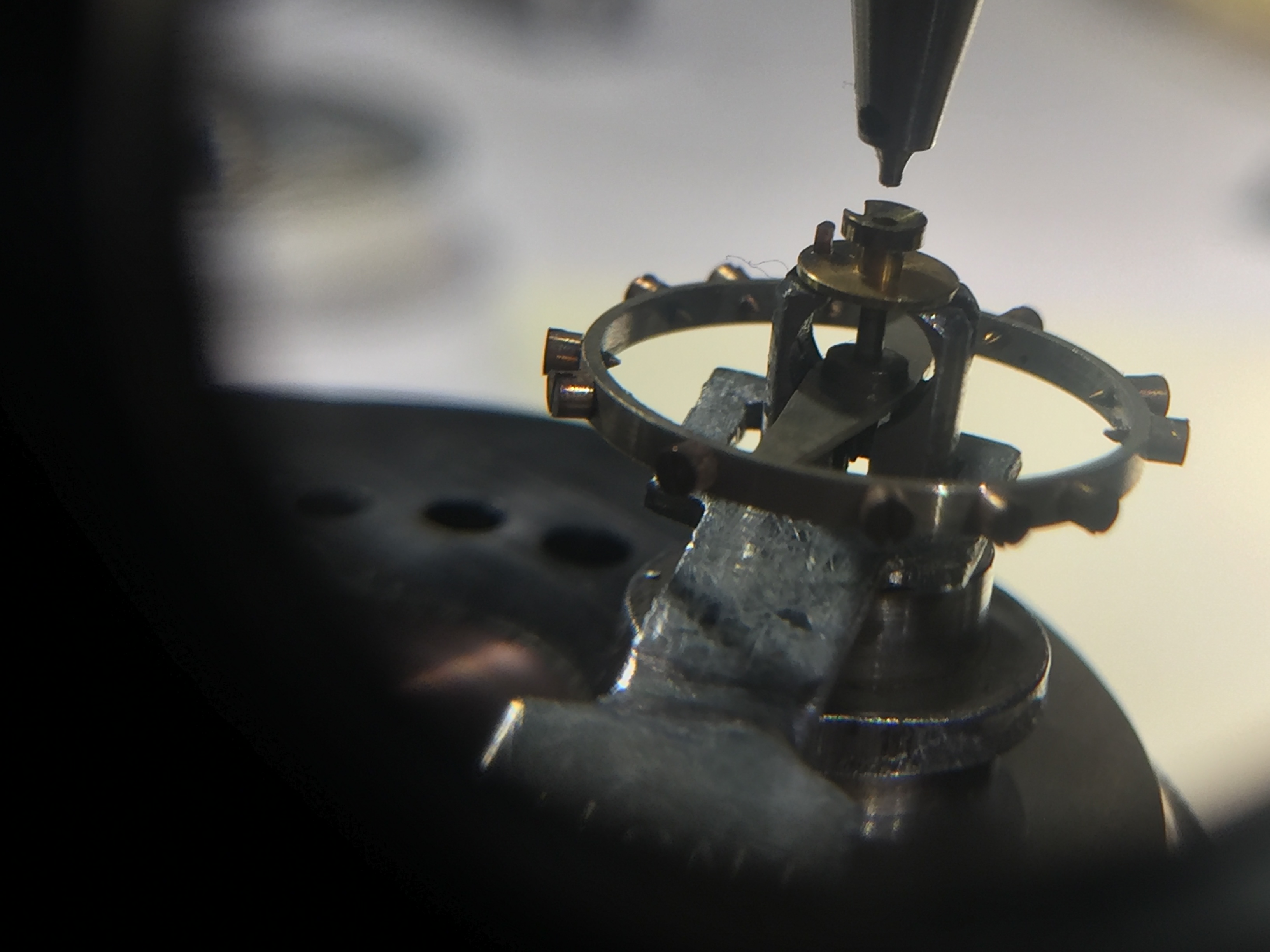
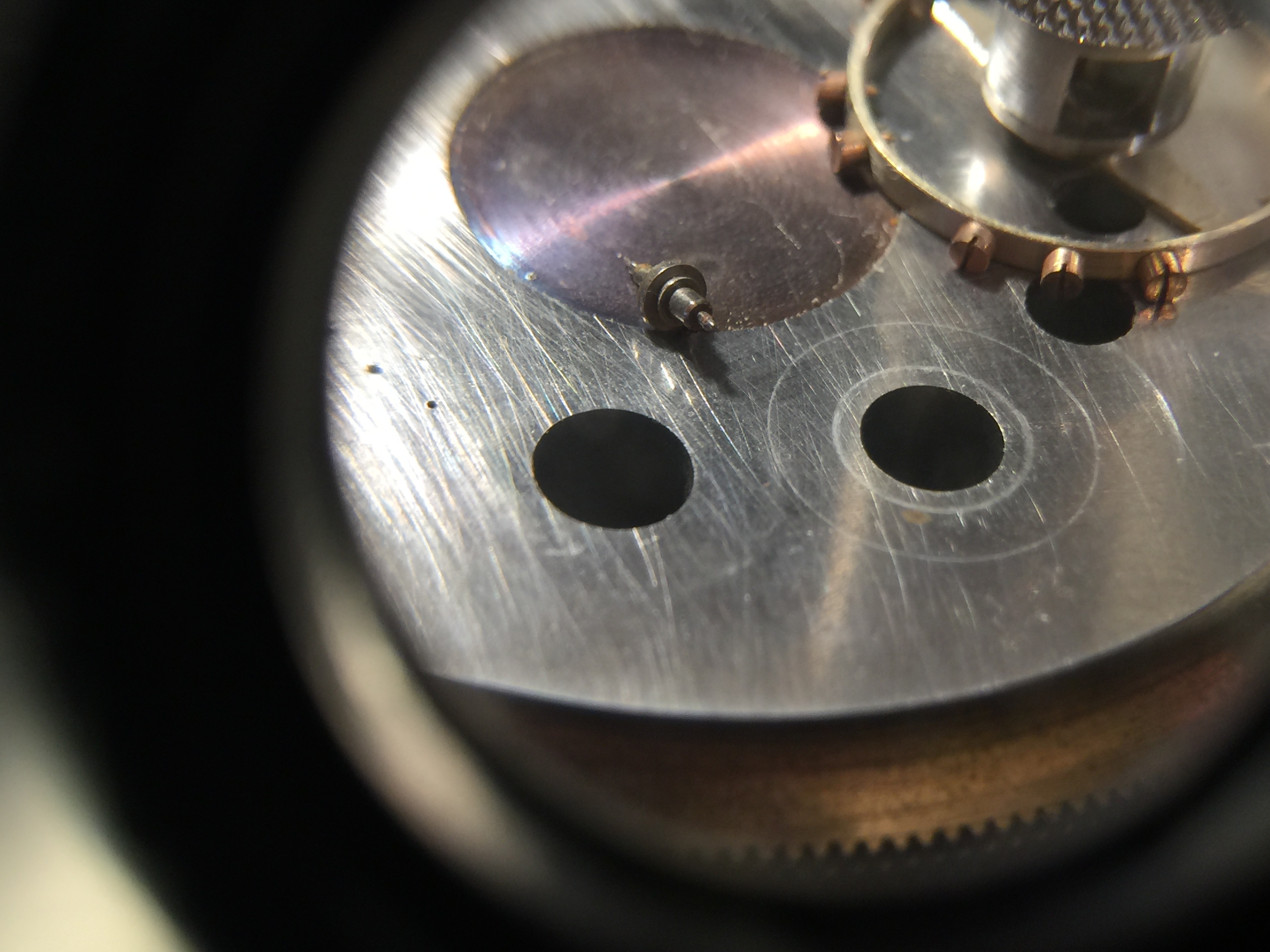
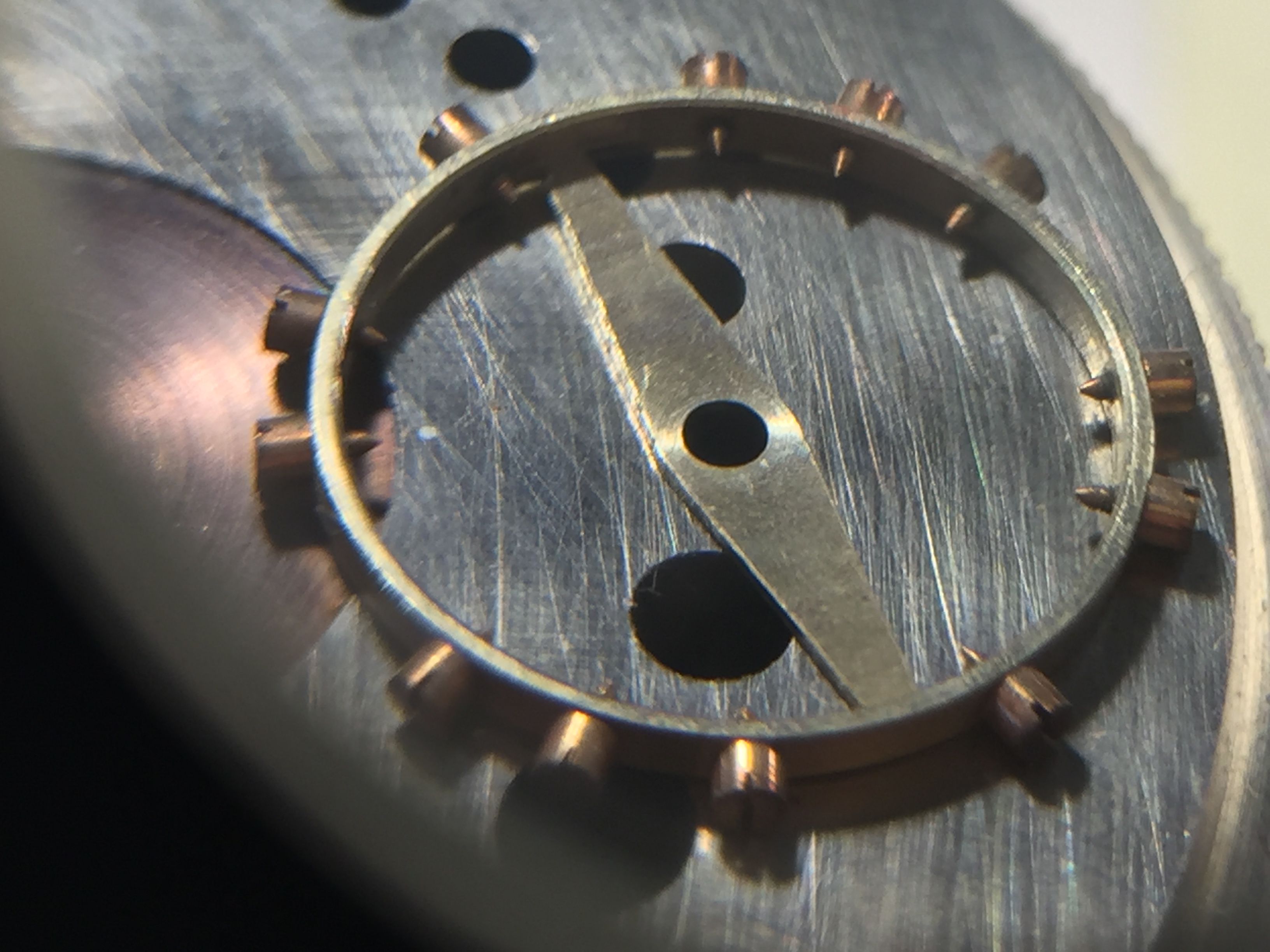
I find the above quotes quite interesting? It's an easy watch the service I don't suppose the parts are really cheap? Then the original posting person is having problems finding the pallet fork in the watch I wonder if that's a problem at all? Actually Rolex watches are really good training watches everybody should start with one. Because every little mistake is going to be really really expensive no matter how easy it is to work on because mistakes will be made by people learning watch repair. I'm attaching an image showing you where Rolex hides their pallet fork. This is an interesting quote? I know I'm being negative how hard would it be to work on a watch obviously not very hard at all. On the other hand how hard is it to break a pivot off, not like any of us have ever done that.
 1 point
 -
Very good. Because of the screw in crown measuring the stem before cutting is a bit more complicated. If you will want, ask here when you're ready and I'll tell you my method. I also recommend that you use a mild locking agent on the crown.1 point
-
One detail is not clear to me. Energy is being transferred to the mainspring barrel; you say it's turning. What's not clear is how far it gets away from the mainspring barrel. The energy that's going in, is not being regulated coming out, or is not actually being stored at all. When you wind it, do any of the gears turn? Do ALL of the gears turn? Sheared teeth is aiming at some number of gears turning with the energy being released fully through the opening created by the broke teeth. The escapement/pallet fork theory assumes all of the gears are turning freely as you wind it. The third option is that the mainspring is broken, and the energy is never being stored for release in the first place. Regardless, the movement is dirty, and a full tear down, clean, and inspection are a good idea; if for no reason other than to be able to fully and more easily assess where the actual problem is. On a side note, living very near to a major IBM facility, I'm curious which one you're near and whether or not there are any local jewelry shops I should be avoiding.1 point
-
Here it is - couple of photos: viewer discretion is advised
 1 point
 -
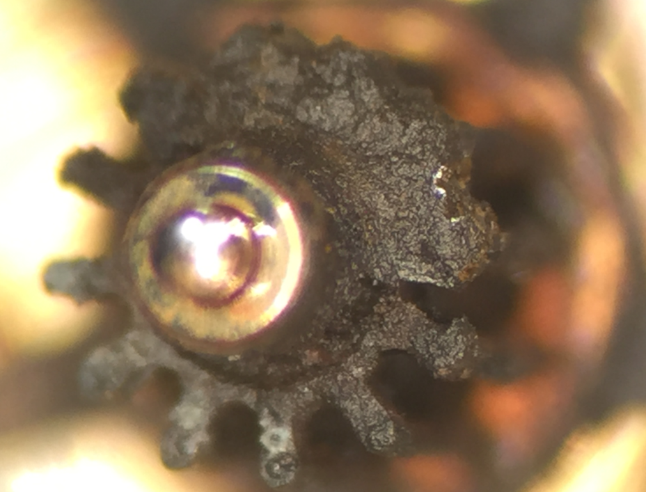
Once I was asked to look at 3135 watch to "see what is going one and why it stopped". That was also serviced just a 1-2 years prior getting into my hands. The back cover was damaged by someone trying to open it using a socket that should be used in automotive repairs. What was inside - difficult to describe... Dirt, moisture, rust, charcoal type of buildup on every pivot, around jewels, broken screw head, old gasket, scratches, damaged screw slots... It looked like ... Anyways, lots of manual cleaning with sharpen pegwood, manual and ultrasonic cleaning in Zenith cleaning solution, some new screws, new gaskets, new case tube o-rings, new crown o-ring, proper oiling - the watch was working and keeping excellent time for 3+ years now. I had a chance to open it a year later after servicing it - no deterioration of any kind. 3135 is not the most difficult movement to service. It is actually a simple one if you know what you are doing. read the TIs, watch Mark's video, get the right tools (screwdrivers, case opener, red oiler at least, Moebius oils) and cleaning solutions - go ahead and slowly clean and reassemble your watch. Leaving it in such dirty state will lead to further wear and damages. Good luck!1 point
-
I have seen "alum" mentioned several times for this purpose. My googling yields several types (potassium, ammonium). Which kind do you use?1 point
-
Hi For your information the whole Miyota OS20 movement costs £15 from Cousins, they usually come with a stem attached. All you need is to recover the crown. If the crown is brass this can be done by dissolving the broken steel stub in a solution of ALUM which will eat the steel but not the brass.1 point
-
Hi I think now is the time to study Mark Lovic's (our Host) videos on the 3135 and build up from there before any real damage is done. to that effect I have attached the service document an two parts sheets should parts be require. I believe there were three parts taking you through the disassembly and re assembly stage by stage. If and when you decide to do the job take plenty of photos at the various stages as a memory aid and for future reference. It may be a Rolex but its no different to any other watch of this type and will require some time and care. good luck. Rolex-3135-tech (1).pdf 2882_Rolex 3135 Pages 6-11.pdf 2879_Rolex 3135 Pages 1-5.pdf1 point
-
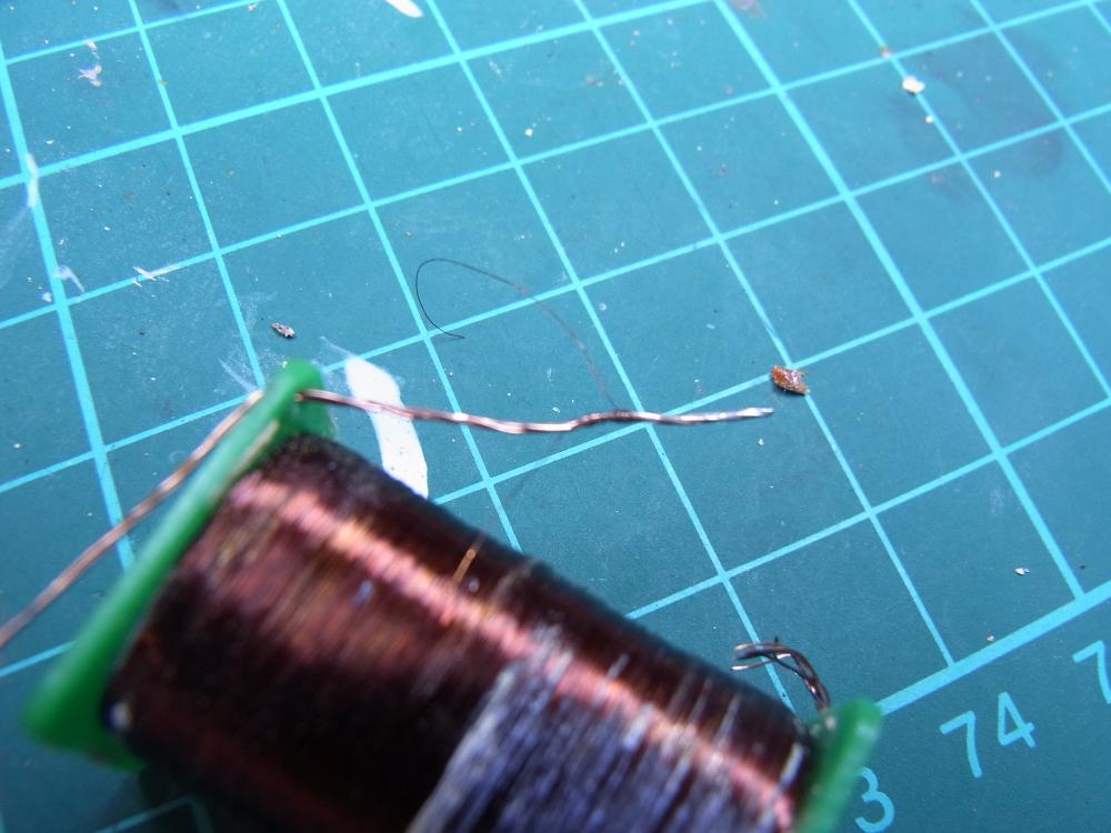
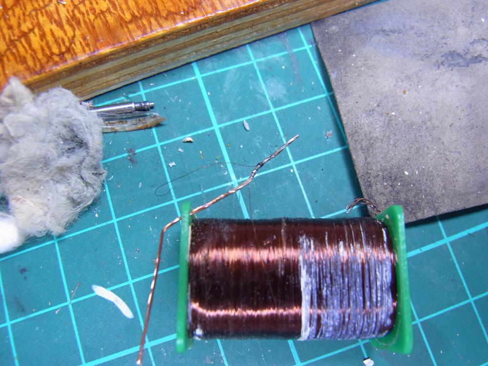
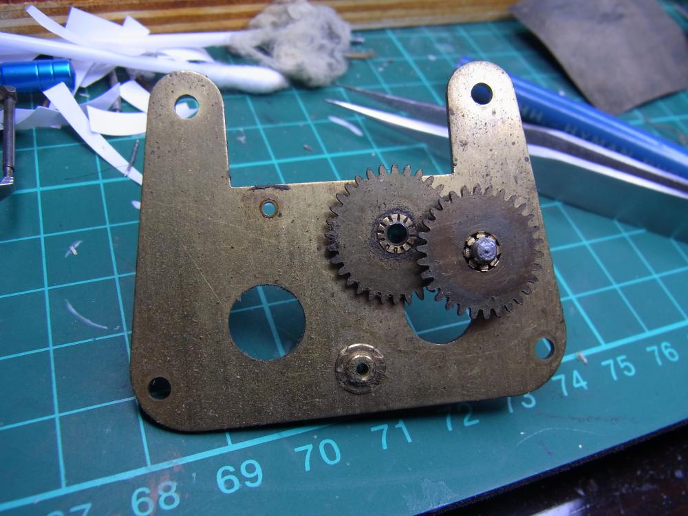
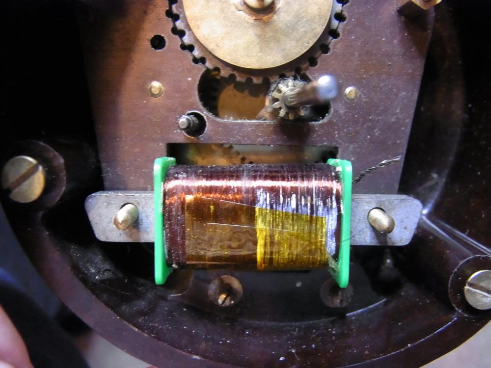
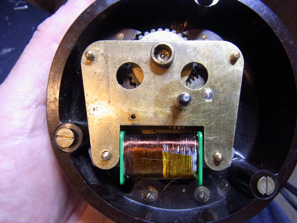
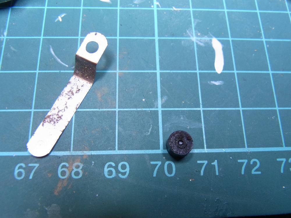
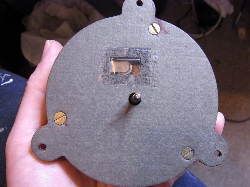
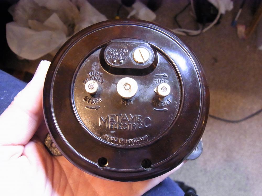
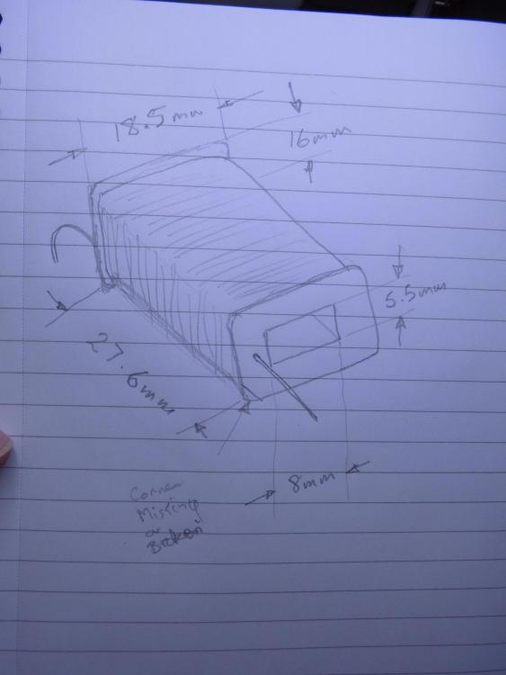
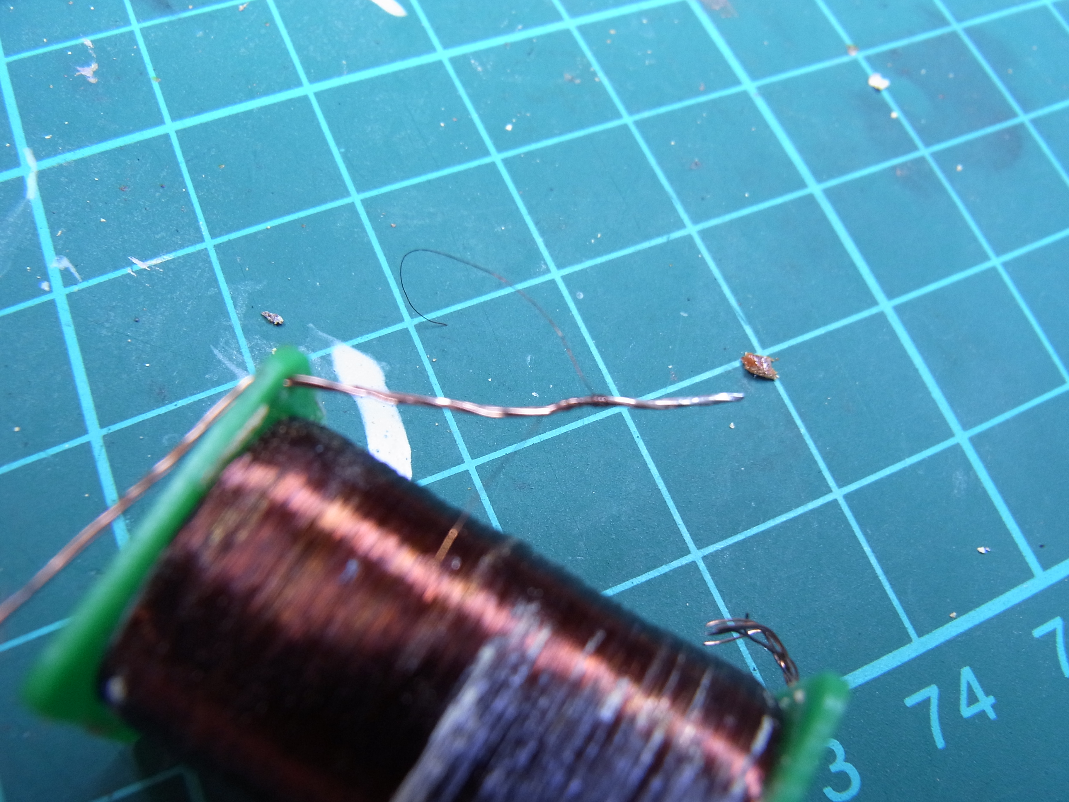
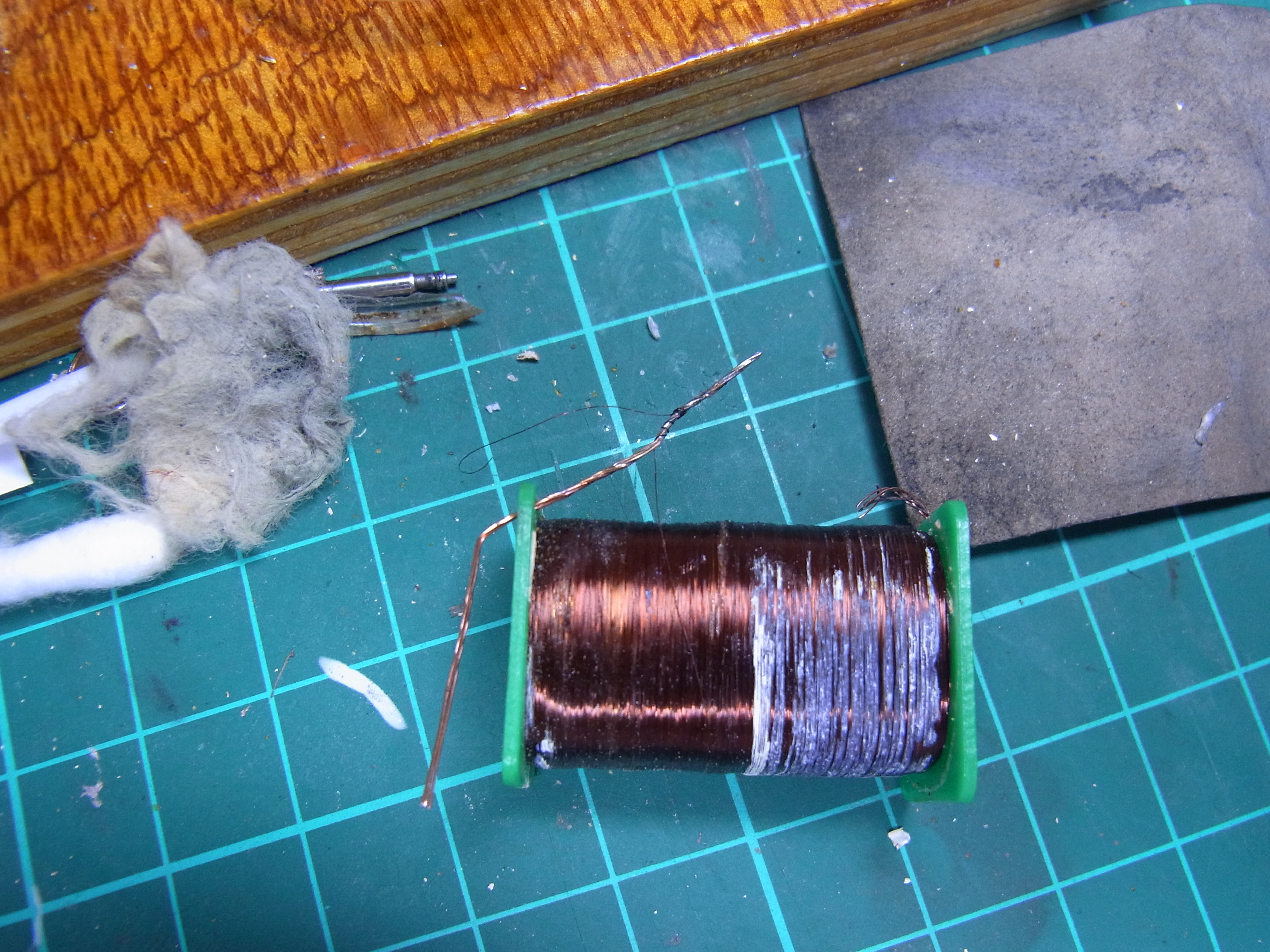
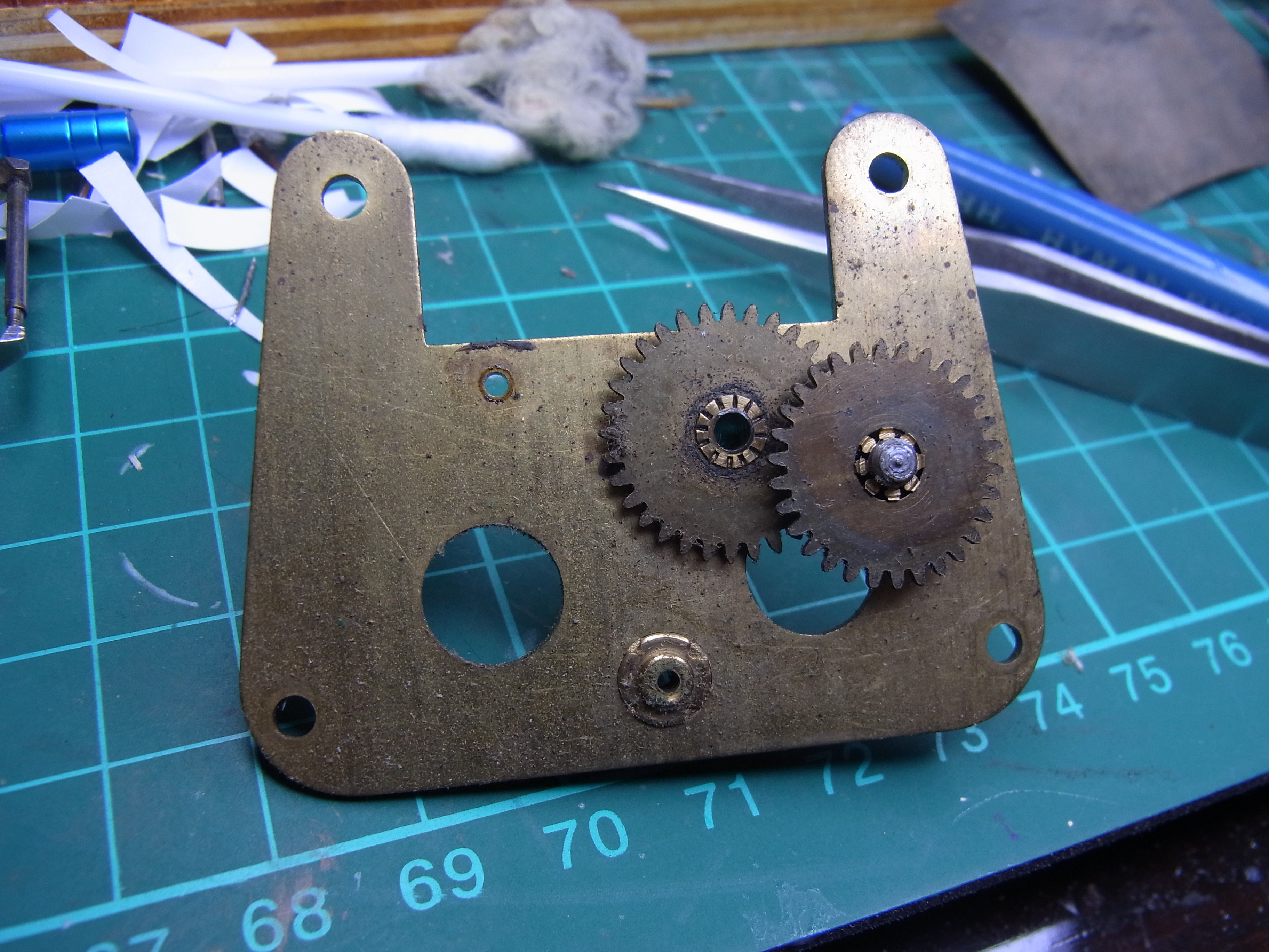
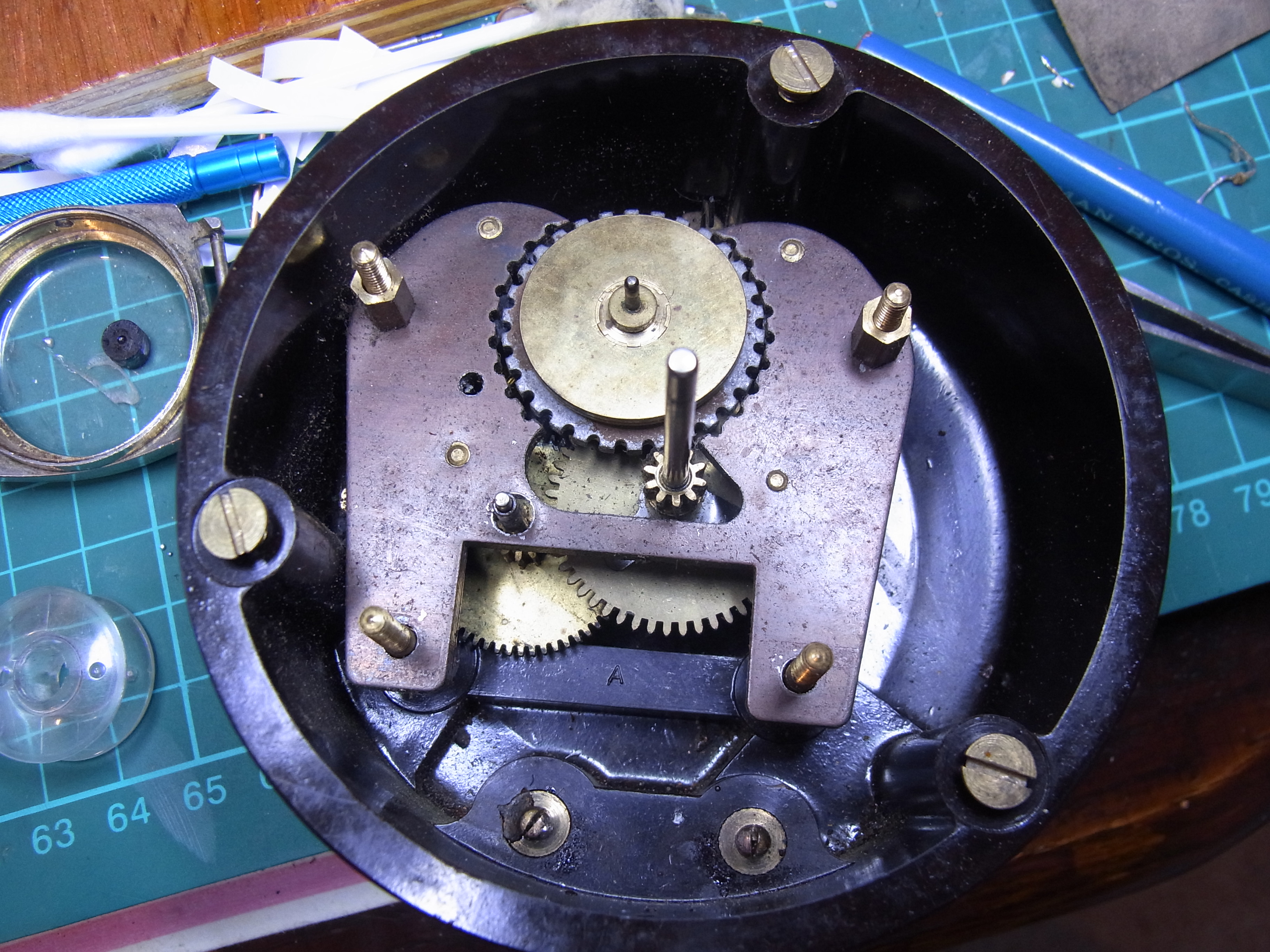
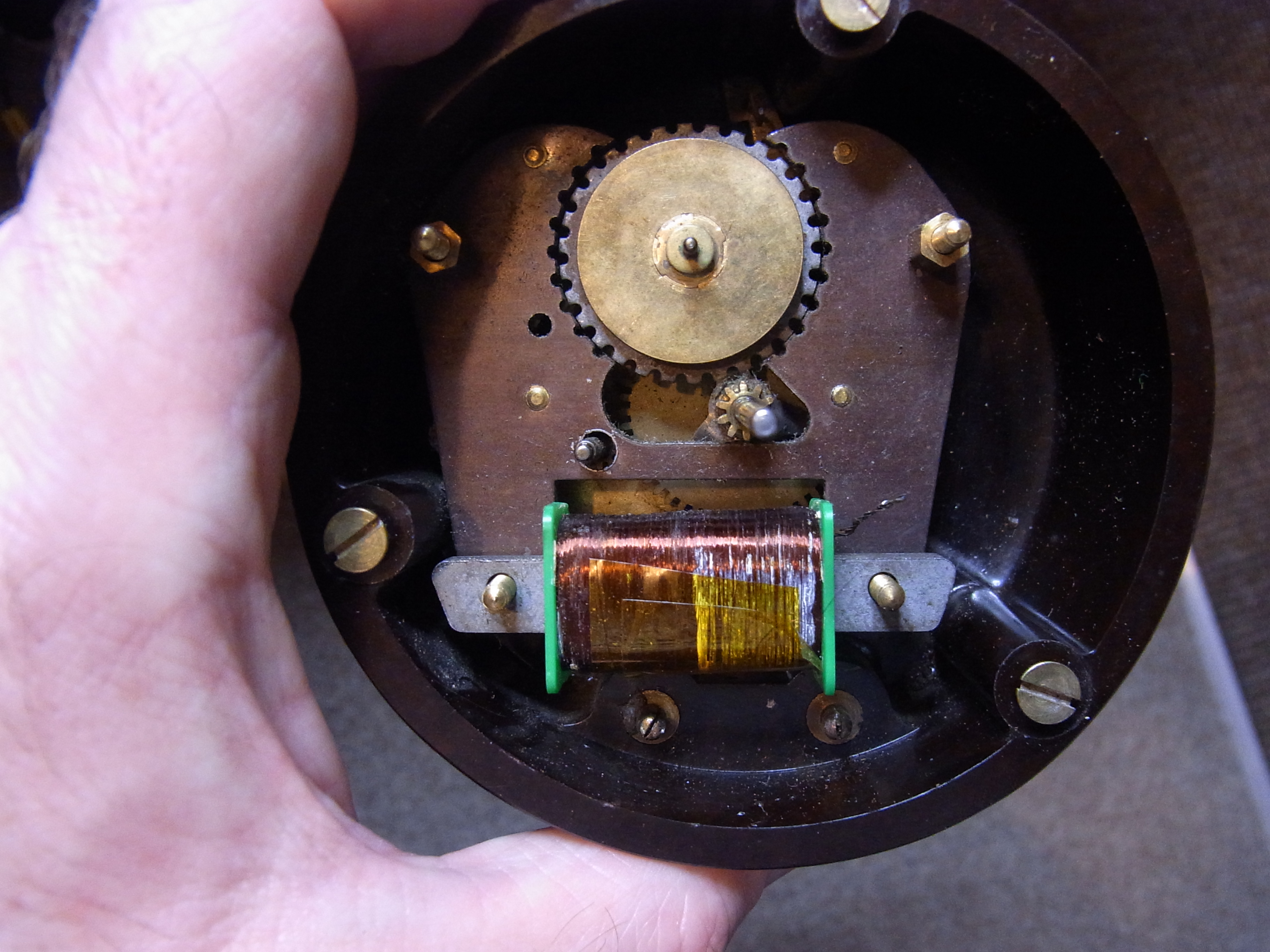
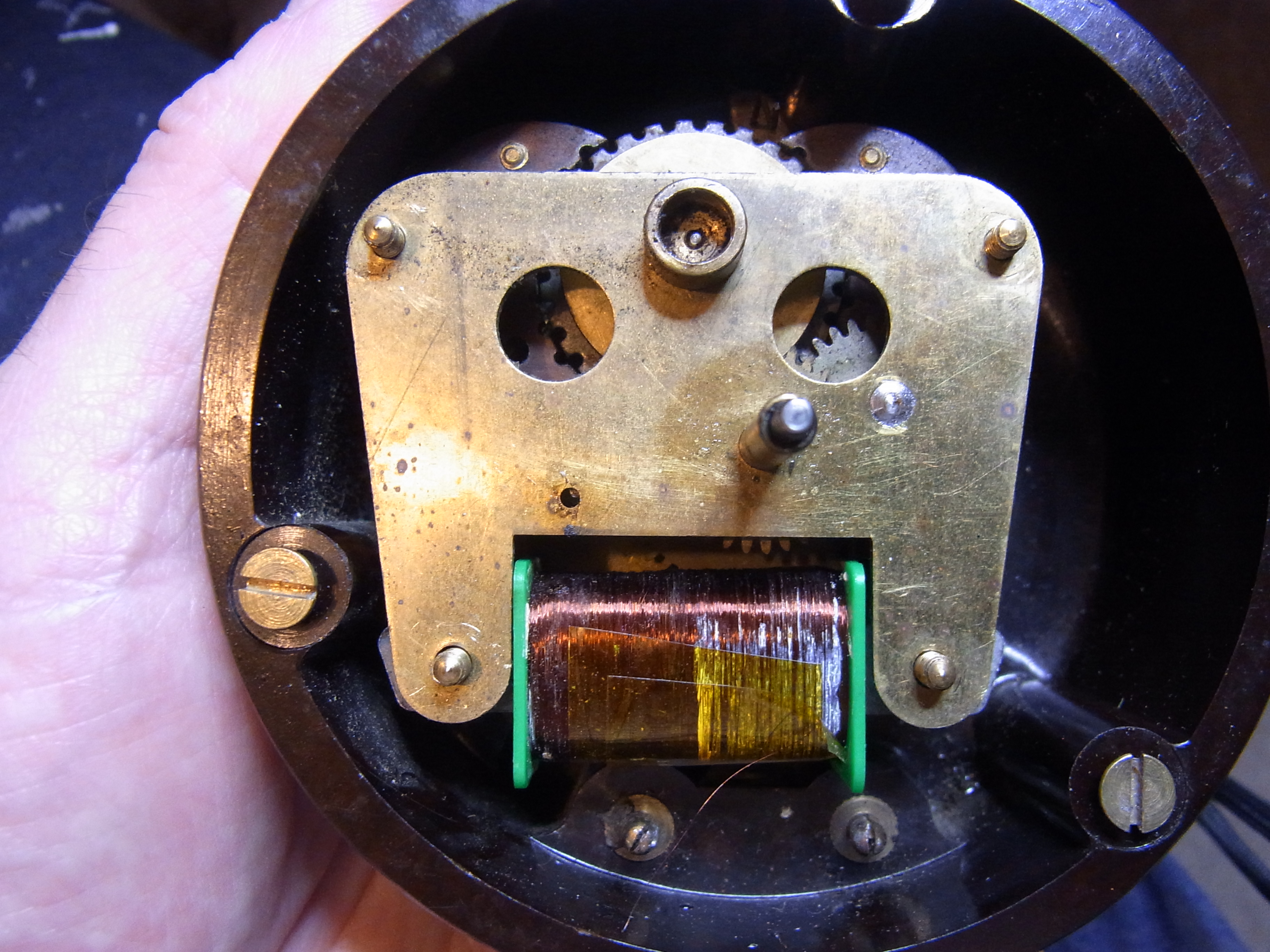
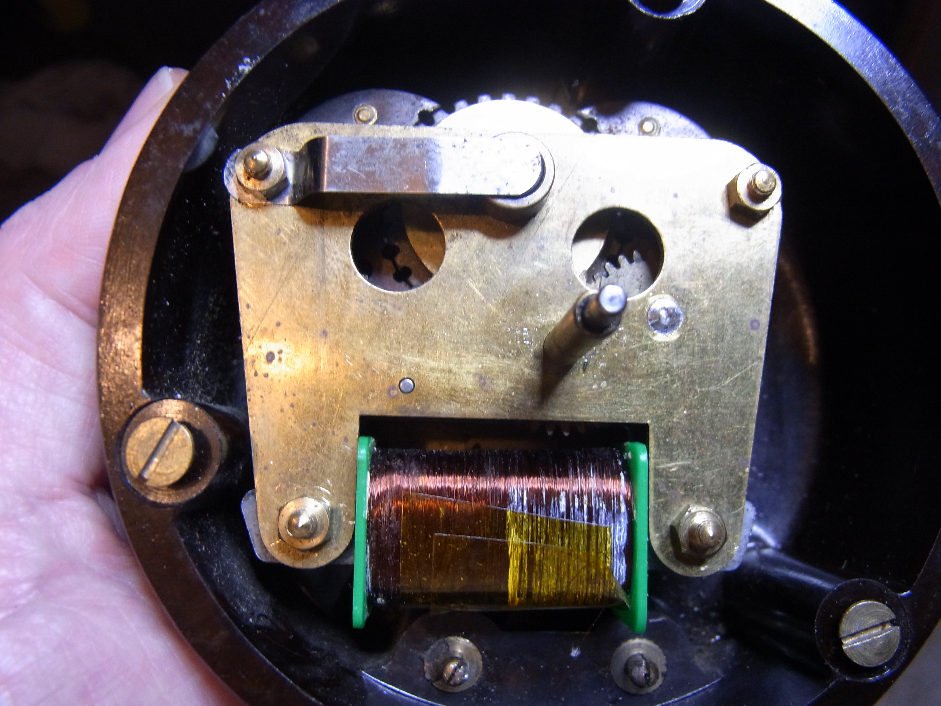
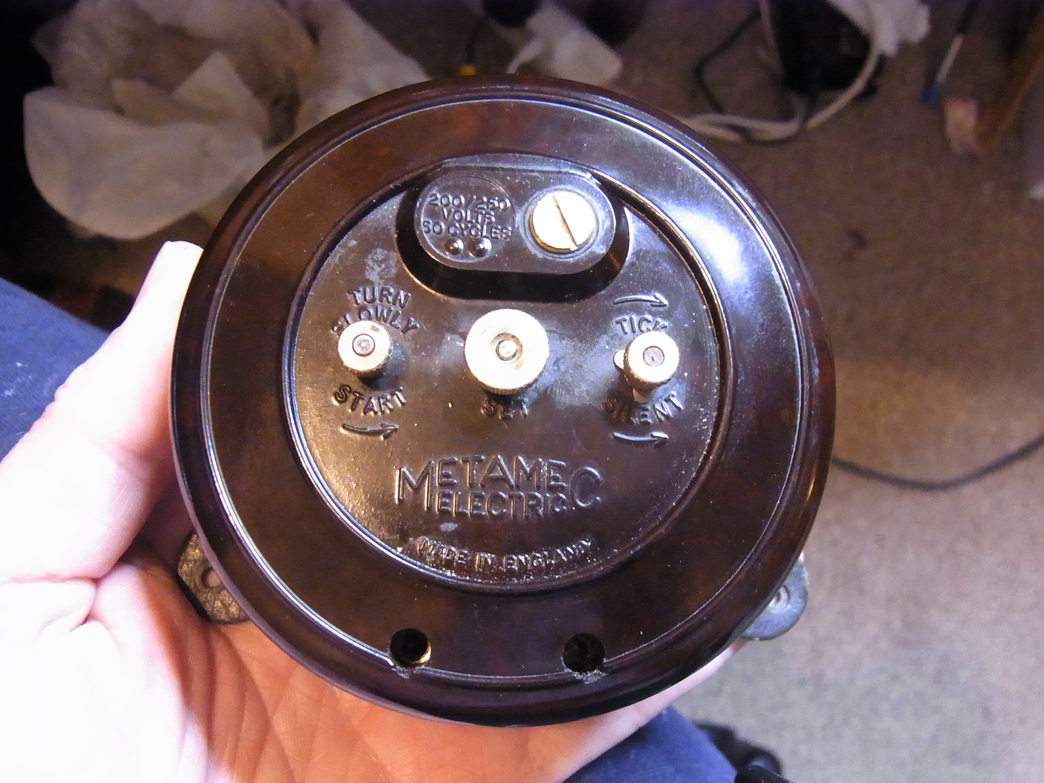
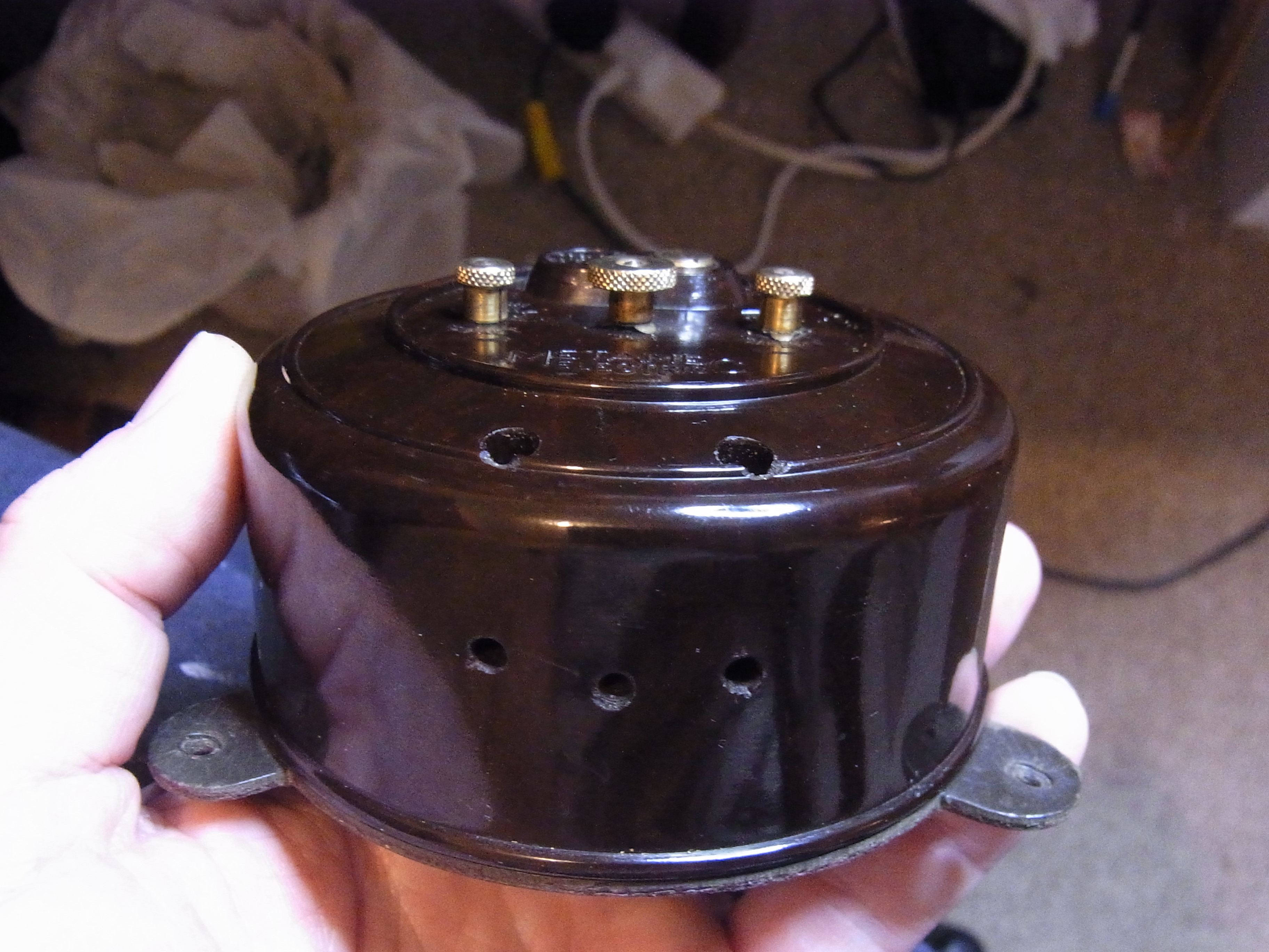
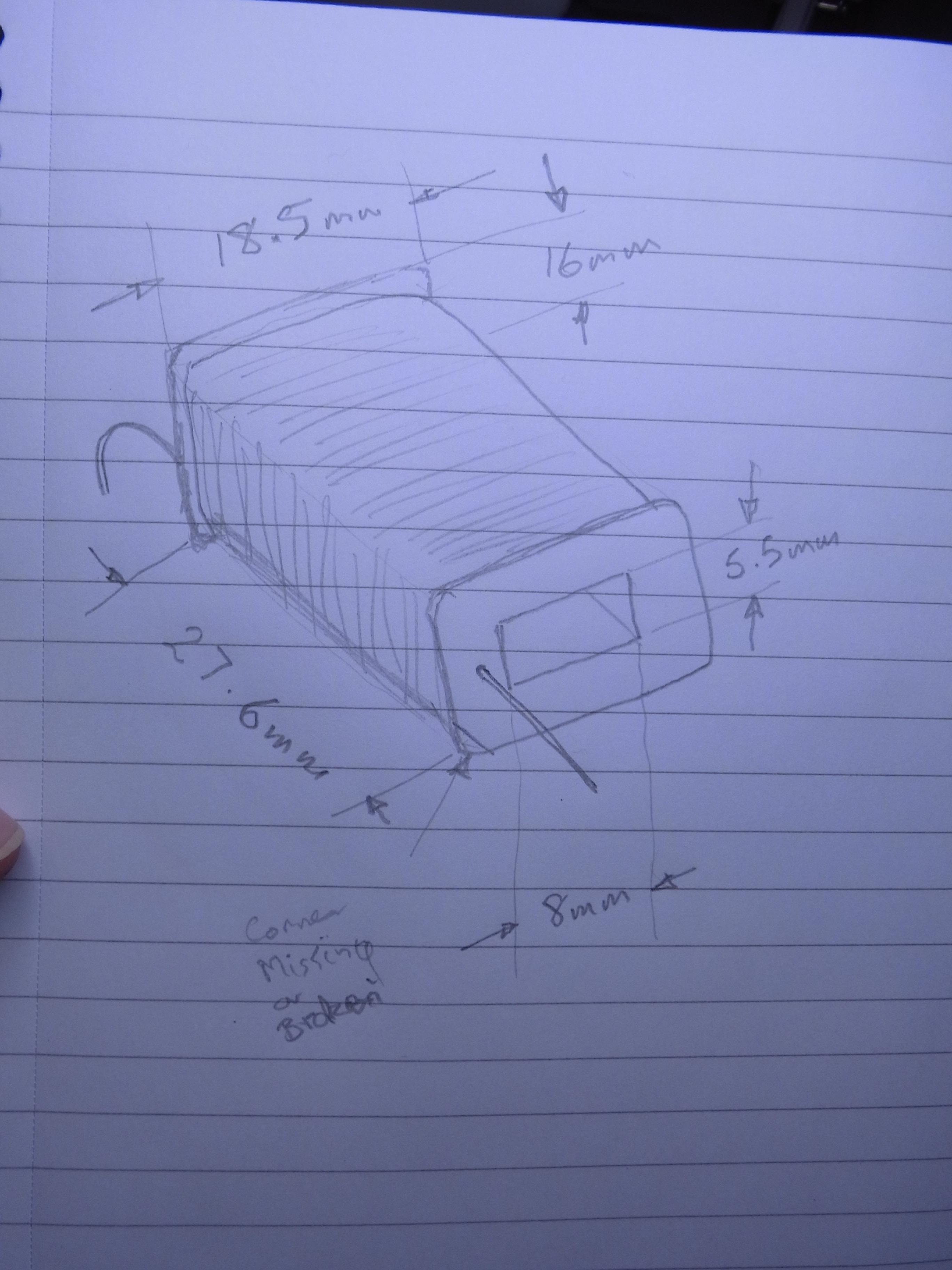
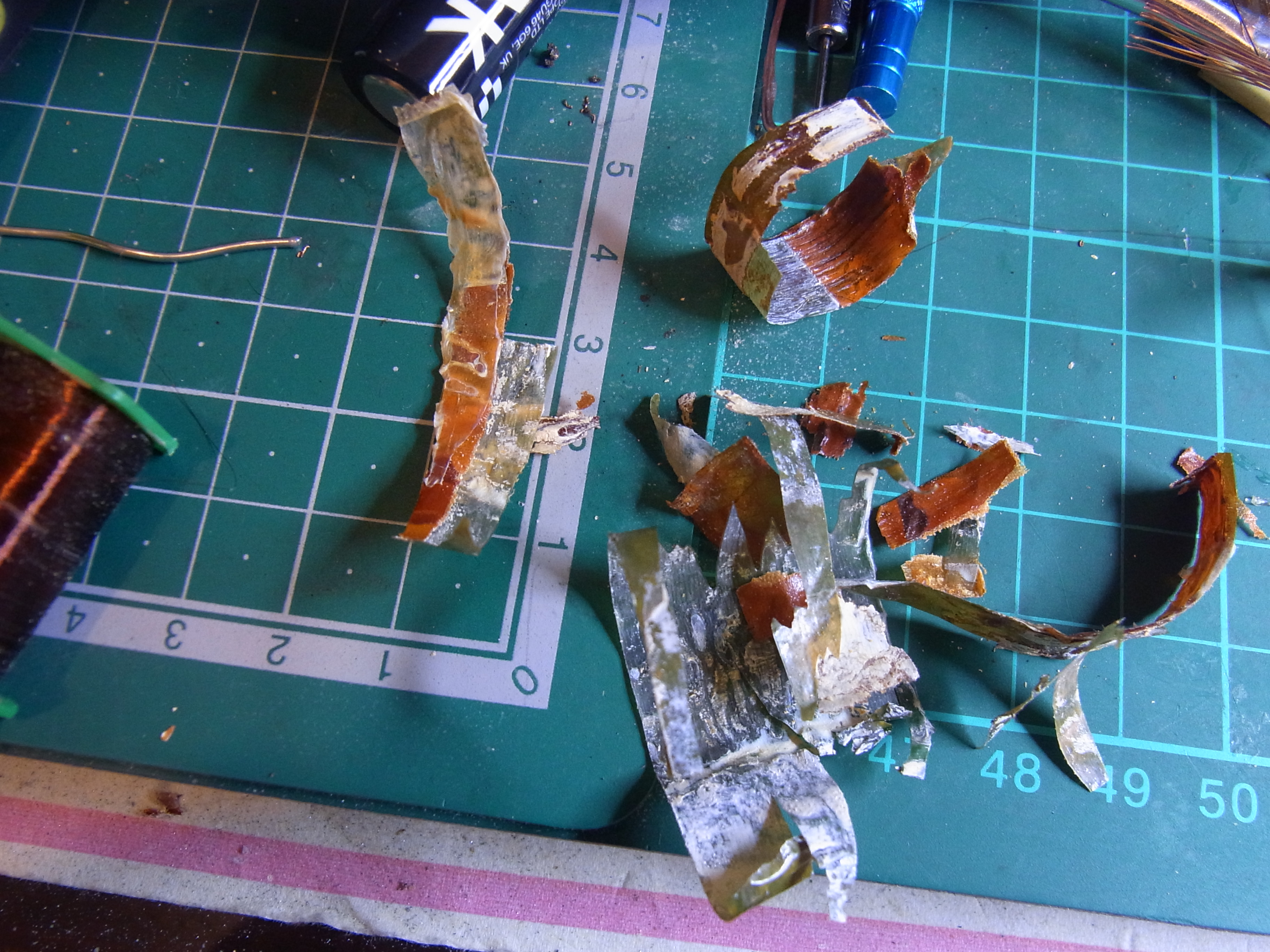
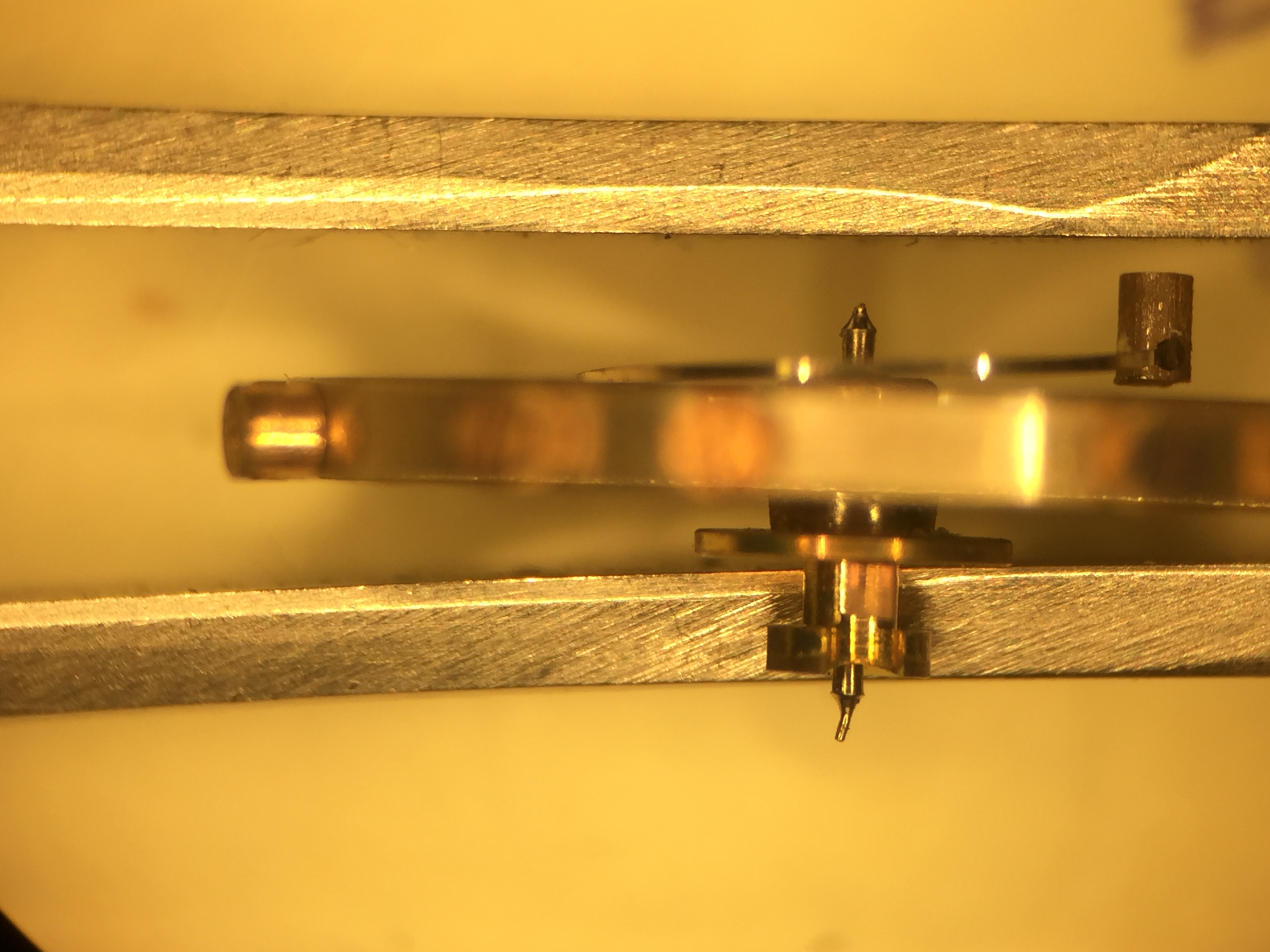
A good question. It looks like trouble. ? I pulled the coil out and unpeeled the top layer to see whether I could simply resolder the feed wires to the coil, but as you can see, despite my best efforts this was not successful. Initially I was hopeful, as the original feed wire had broken from the tab due to corrosion caused by the ancient rubber insulation decomposing and absorbing moisture. The problem is though, that this corrosion may also have affected the inaccessible inner feed wire. It appears therefore that the break lies either on the bottom attachment (which would necessitate unwinding the entire coil) or it lies somewhere in the middle. I've attached some pictures of the mechanism and my failed attempts to fix the coil. The dimensions of the coil are in the sketch in the last picture. You can see from these images that the dimensions of the coil are fairly precise as it just manages to squeeze in to the space. Since I don't have any idea what the original resistance was, I'm a little reluctant to attempt to wind the coil with fresh wire (which I could probably do using the seweing machine), since getting this wrong runs the risk of winding a coil that runs hot which might be a little exciting, or one that has insufficient oomph to turn the motor. I guess I could un-spool a meter of the wire and measure its gauge and resistance, then simply count the number of turns on the coil, but frankly that does sound like a lot of work. By the same token I'd rather get it working with the original mechanism than take the easy route and fit a quartz mech. I've put the mechanism back together for the time being, to ensure that I don't loose anything, while I ponder what I'm going to do next. Wrapping the enamel wire on to the new feed wire. The core copper wire is approximately 0.04 mm in diameter, or roughly half the thickness of an average human hair. 46 awg wire for comparison is 0.039mm in diameter, so I think it would be safe to conclude this is 46 awg. However your guess is as good as mine regarding the number of turns on that coil. Soldering the enamelled wire on to a replacement feed wire. The rear of the front plate showing some of the gears. The failed repair re-fitted to show the clearances. Those two pins at the bottom are where the feed wires would attach with tabs and the mains cable would attach from the outside. The "bearing". I'm not sure what exactly this is made of, but it may be graphite. It is not an electrical contact and brush, as you might think. The only electrical part of the clock is the coil. The motor needs to be spun in the correct direction following loss of power by a mechanical contrivance operated from the back of the case. The spring and bushing refitted. There is a similar bushing on the other end of the motor shaft which can be accessed using the wide brass grubscrew like widget on the rear of the case with the screw slot in it. That strange window lets you see if the motor is turning. Presumably this was used in the factory when testing. The "control panel". On the left the "kick start", followed by the adjuster for the hands and the "tick/silent" control. The bushing on this side is behind that wide brass screw. It looks exactly like the other one. The mains wires were originally fed in to the lower left and right holes and clamped in place by grub screws accessed from the top two holes. There was no earth. That middle hole in the bottom was for a cable clamp screw. The top two holes are therefore where you poke your screwdriver into the live terminals when the power is connected if you want to entertain your audience by connecting yourself accidentally to 240 V AC and blowing yourself across the room, with much foul language. Elf and Safety 1950s style. The dimensions of the coil including the sizes of the hole for the iron core. There is a corner missing from the plastic former. This may have broken off, or may perhaps have been removed in the manufacturing process to ensure the coil is orientated correctly while assembling. However since the motor is not self starting, and needs to be spun in the correct direction by that knob on the back every time the power is lost, I suspect the direction of the field is not important, so fitting the coil back to front probably wouldn't make any difference.


 1 point
 -
The case reference is not important, you need to look at the identification on the quartz module. For the best results I recommend you give it to a watch shop, it should not be an expensive repair.1 point
-
A beauty1 point
-
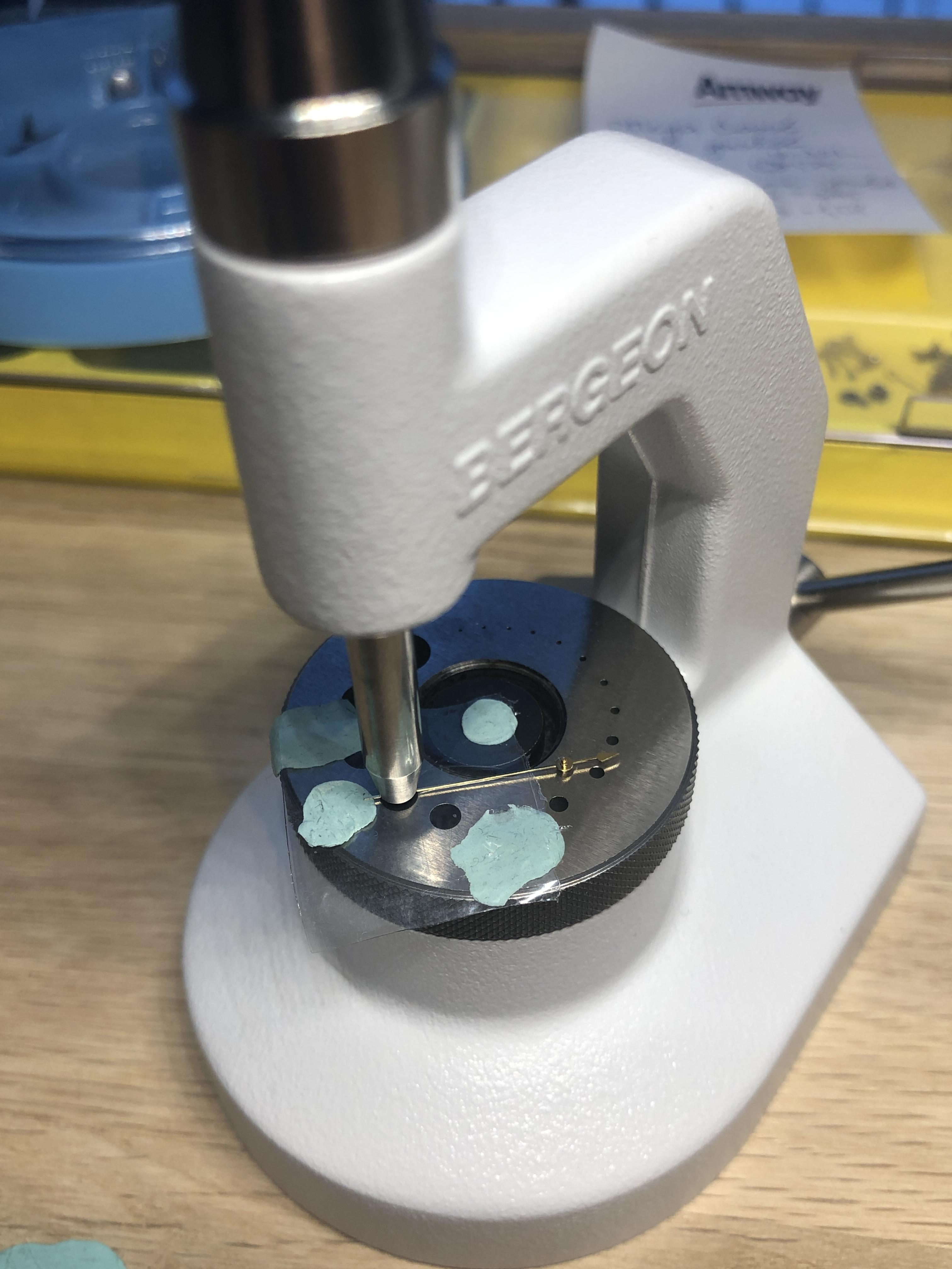
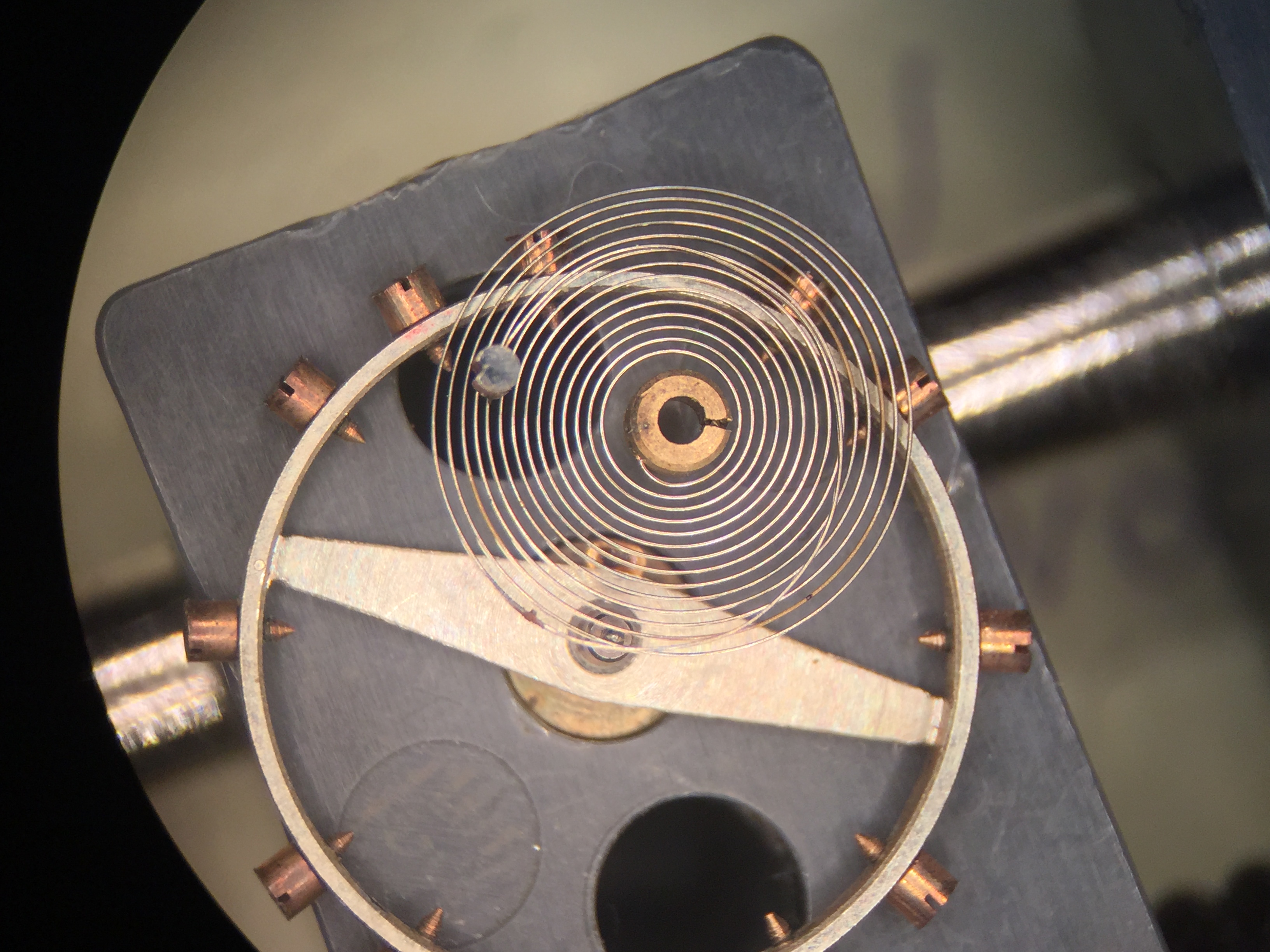
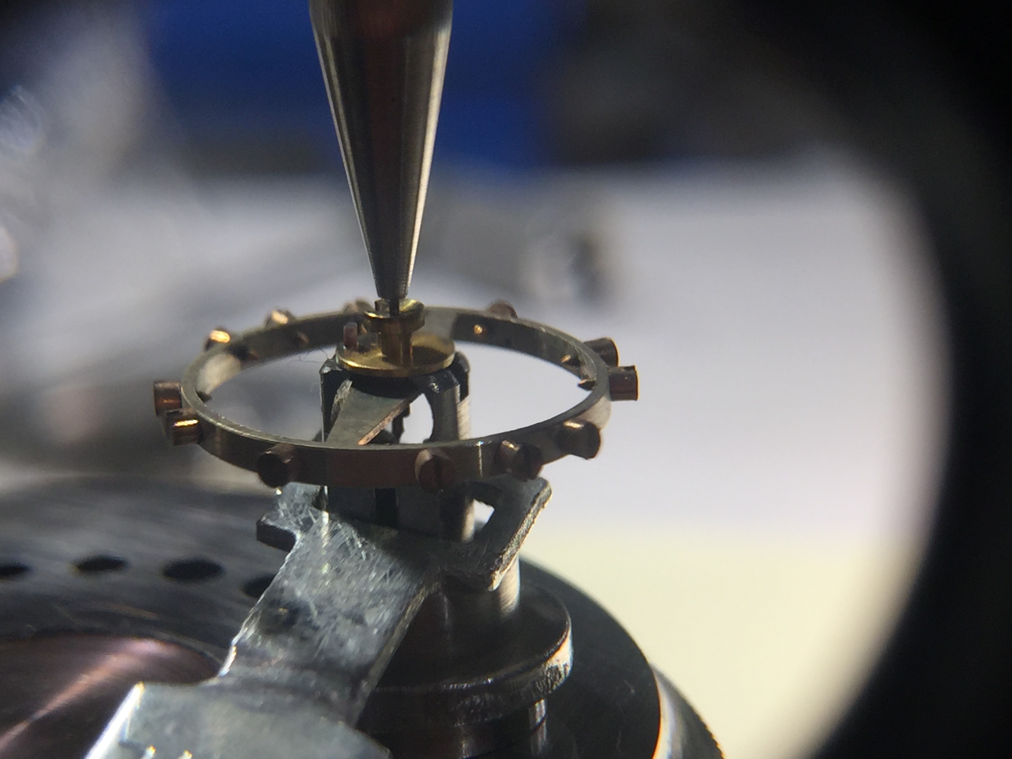
Life would be tough without K&D Inverto Staking Set and K&D Staff Remover No.50 Hairspring collet removal was done with the help of a small flat screwdriver inserted into the collet split to expand the gap. Everything else is self-explanatory (I hope).


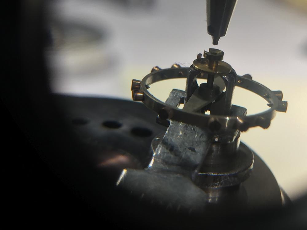
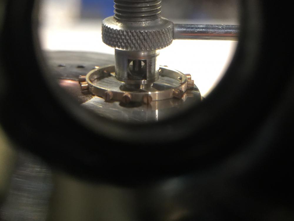
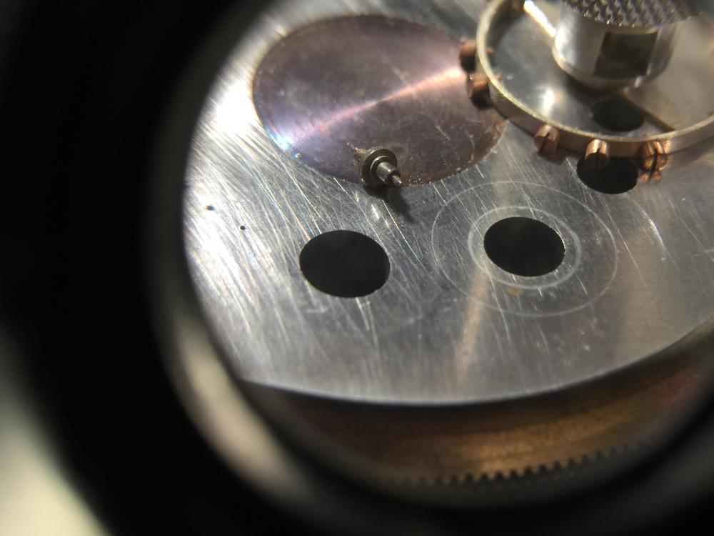
 1 point
 -
So it's been a really really long time. We moved, much bigger house that needed lots of repairs but closer to my work and much better schools for the Kids- yeah we had another one of those too Now I've reached a point that I can start working on my workshop (woodworking and beer brewing) area and also my watchmaking area. To celebrate this and my recent birthday I picked up a 1970 Bulova Sea King Automatic 11 ANACB. Currently it has several issues but hopefully, they will get resolved quickly! Dan
.thumb.jpg.c6ae53c2608b2afcdce9570b53a8727e.jpg) 1 point
1 point -
Hi, Your post will get more exposure if you create a thread in help&repair section, A picture of IBM double O zero project will help.? lol Lets hope no part is damaged. Your watch will be fixed. Welcome to the forum. Regs Joe1 point
-
It's always amazing what you can find online if we take the movement number and the name they come up with the links below both of which suggests that the movement is based on ETA 2783. From that we can a parts list. https://antiques-atlas.com/antique/gents_unusual_1970s_silver_wrist_watch_garrard/as170a7214 https://www.birthyearwatches.com/product/1974-garrard-9k-gold-automatic/ 496_ETA2750,1,2,6,4 ETA 2783.pdf1 point
-
LWS, I think it is dangerous to use the term "interchangeable." Similar to both Ronsonol and Drizebrite, Coleman fuel (aka white gas) is also a mixture of hydrocarbons and classified as naphtha. I am not a petroleum chemist and there are several aspects of the classification and description of naphthas that are unclear. But they are all mixtures of low-boiling hydrocarbons that should dissolve oily, greasy watch parts similarly. I would give it a try but would still rinse with isopropanol. What I did notice in the MSDS for Drizebrite is a boiling point range of 300-350 degrees F, which is a relatively narrow range for naphtha; so I highly suspect that the manufacturer further purified whatever they got off the truck or out of the bulk supplier barrel. I didn't see this info in the others' sheets so it's unclear whether they are further purified or not. Some technical things like this are kept as trade secrets, but sometimes the companies just don't bother to fill in on the sheets as completely as they could. For those that care, the CAS number for Ronsonol lists a composition of predominantly 4-carbon thru 11-carbon compounds; that for Drizebrite lists predominantly 6-carbon thru 13-carbon compounds; and that for Coleman fuel lists predominantly 6-carbon thru 9-carbon compounds. So, likely a lot of compounds in common and a lot not in common.1 point
-
Resoldered the wire adding just a dot of silver solder past and a quick reheat. The plastic should be Nylon so I wasn't overly concerned as long as it we out quickly. Recurved the hairspring and it's up and running once again. It now probably needs to be reregulated since it lost the 1.25mm of spring trapped under the retaining pin when the balance was wrenched out but I'll let it run until that happens. HectorLooi, thanks the interaction. JerseyMo, thanks for your input as well. I sent you a private message. VID_20210116_161652~2.mp41 point
-
Press-fit a pendant tube in that hole, there's a special tool for this. That's going to leave you with a pendant tube OD of 2.5mm. The crown fits over this to form a waterproof with a rubber seal inside the body of the crown. You have chosen 5.0mm crown diameter, you still need to know the tap size (metric diameter of the threads on the winding stem, commonly 0.9 but also other sizes). Those 3 numbers, plus the finish (stainless, gold, etc) and the type (waterproof, swiss style, domed, etc ) will find you a crown. Older, cheaper, non-waterproof watches just have a hole with no pendant tube and no seal, or sometimes a notch in the case rather than a hole, so the movement with stem fits into the case and a press-on caseback holds the movement and stem in place (often seen in "ladies" cocktail bracelet watches)1 point
-
So after all I covered staking set anvil with square from plastic bag. Pushed on hand with round head punch. That worked really good. Specially that possibility of measuring quite accurate adjustments. I needed to be quite accurate since slight doomed crystal. If someone feels like trying this. Make sure you use strong and thick plastic bag, or anything that will preserve hand surface from receiving scratches from anvil.
 1 point
 -
Bam!!! Another mystery solved. I was looking at that tool in my dads watch bench yesterday and wondering what it was for. In the same drawer is a container of broaches. Voila!!1 point
-
Now it's back where it belongs to.
 1 point
 -
And us guys who are computer challenged appreciate people like you who have stuff and share it with guys like me. In other words, thanks John! It does not go unnoticed. I've been trying to get better at finding stuff on my own. Still is fun asking and meeting new people tho!1 point
-
My interest in these started a few weeks ago when I won this Ferranti Art Deco style electric clock on eBay...... https://imgur.com/4Wh0OlR https://imgur.com/ojHknNv https://imgur.com/Npw4rYq I wasn't sure if I could restore it and get it going but for the princley sum of £14 I thought that it was worth a try.... Any way an hour or two of work saw this, all restored, re-wired and up and running:- https://imgur.com/SU3ga2R This started the fall into the abyss........? The next acquisition was this Ferranti bedside alarm clock....... https://imgur.com/pXh6leY https://imgur.com/GeNN3Hw Which also was an easy restoration...... Now there were two....... https://imgur.com/VTUVzhX At this point I realised that I needed more information on Ferranti synchronous clocks so bought a copy of this, the diffinitive work on the subject..... https://imgur.com/LolepmD Which told me that my two Ferranti clocks had both been made between 1947 and 1952, so not as early as I had originally thought... Two was obviously not enough.........? These things are adictive! I could not resist this period green offering from Smiths, again a bedside alarm from the late 1940's, early 1950's.... https://imgur.com/94e3sFx Now restored..... https://imgur.com/TFsLrQI I was less enamoured with the Smith's movement than the Ferranti ones and the next acquisition was this Ferranti Bakelite mantel clock, which my new book of knowledge informed me was one of the first from about 1933..... https://imgur.com/NkXzMtQ Again a fairly easy restoration....soon fully restored and running....A picture of the rewired movement here:- https://imgur.com/XMK4rrB At this point I started to feel like Alice falling down the rabbit hole.....? Another Ferranti Bakelite bedside alarm followed, this time one from the mid 1930's https://imgur.com/iAKYfF5 This one cleaned up well, and is now running, but the dial is a bit of a disaster and because of that I have yet another incomplete one the same type, but with a better dial, coming as donor....... Oh and I 'accidentally' bought a second round Bakelite alarm, identical to the first one..........seen here with the restored mantel clock... https://imgur.com/C7exLkq now fully restored, I shall have to sell one of these to help pay for my addiction......? Now at this point £14 was the most that I had paid for one of these, several being £10 or less but when I saw this hexagonal, pewter cased, one I had to have it and ended up paying almost twice what I paid for the first clock...... https://imgur.com/aOm7IAj https://imgur.com/KAHUrNW The dial appears to be a major problem but we shall see..... Well it arrived this morning, so I couldn't resist seeing what I could do with it..... I stripped it down, noting that whoever had previously been inside it had assembled it with the chapter ring the wrong side of the glass, causing the hub of the second hand to be firmly clamped by the glass.....perhaps that was why it was sold as 'not working'?? I determined that the coil was not short or open circuit and the resistance was correct, at between 4 and 5K ohms, so in for a penny, in for a pound, in true old master painting restoration style I started to attempt to clean up the dial using cotton buds, saliva and mild soap and water.....Much to my surprise, after an hour or so i had got it to a very acceptable level of appearance. All that was left to do was to clean up the case parts and glass, finally giving the pewter case a spot of car polish.....and reassemble it all, wiring it with a new flex.... Voila, the finished result ? https://imgur.com/ArXGRnN Watch this space, there are more on the way!? Can someone explain how I can get hosted pictures displaying instead of just the link?1 point


.jpg.bb1d726431c4c11edd3041ed1806c0f3.jpg)