Leaderboard


Popular Content
Showing content with the highest reputation on 10/17/20 in all areas
-
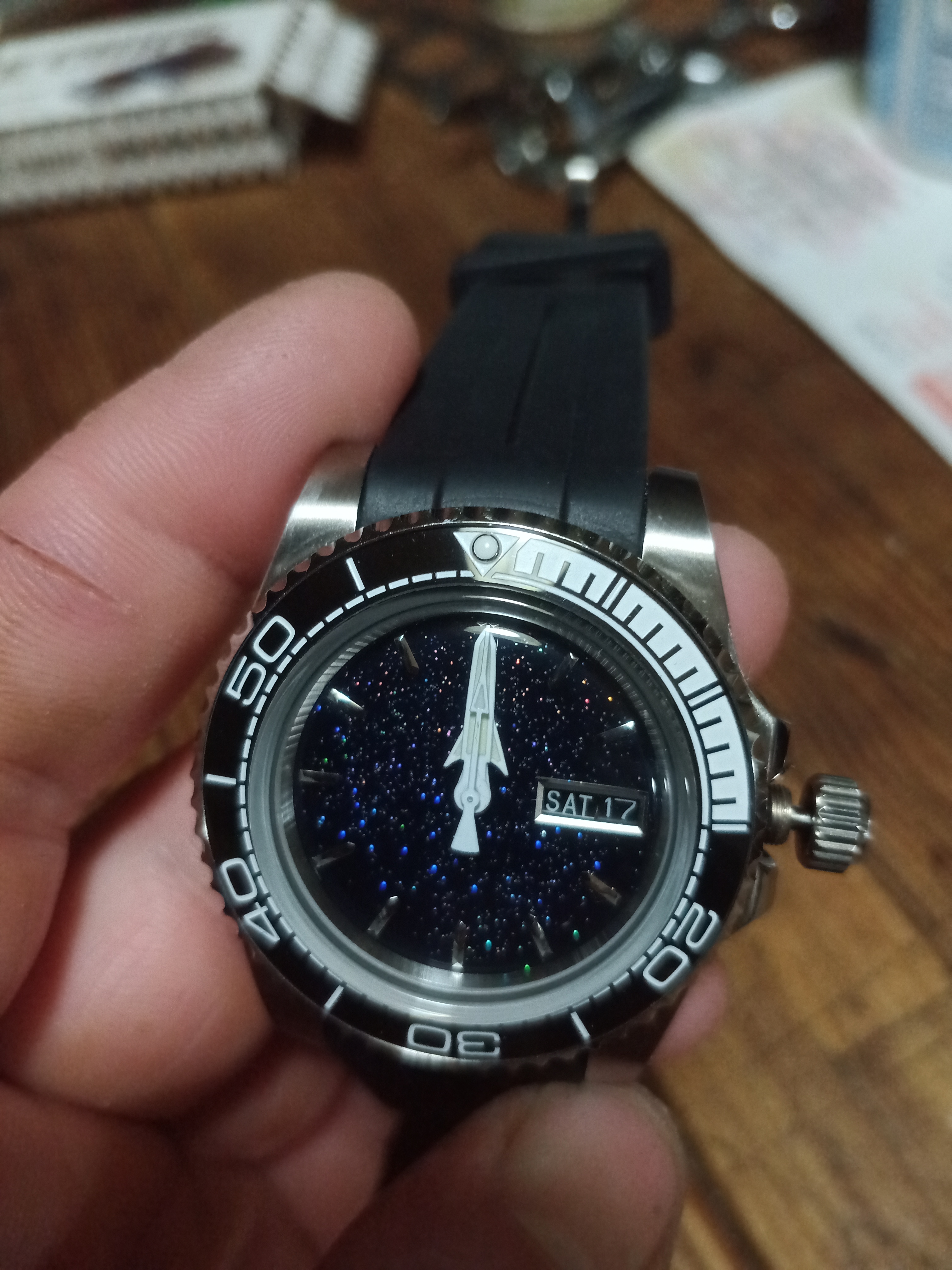
Turns out it wa just the wrong date ring... Got the new one and now I'm all set- rocket ship in space build complete!
 3 points
 -
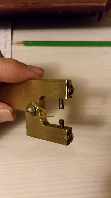
A little while back, I made this set of trueing calipers. It was originally meant to tide me over until I could buy a pretty, vintage, German pair I had my eye on. It's just a billet of brass which I cut to shape, and where I drilled a single hole through both arms for the pivots, then holes for the set screws which I tapped for threads, then a threaded hole for the reference arm. The pivots are just thin steel bar stock with highly polished divots in the ends. I keep not getting around to snatching up a nice vintage set. Mine works well, despite lacking any real aesthetics, so I just keep using it when I need to. But I swear, one day I WILL pick up a nice German pair. One day.
 3 points
 -
The Bergeons above are specifically for checking balances for flatness, and in the case of split balances for trueness in the round (a solid balance that isn't round or is eccentric is a bigger problem than what these can handle). The pivots are held by the conical portion, and quite a bit of force can be exerted on the rim to bring it true. The adjustable "finger" is for a visual reference while truing. The truing itself is done simply by finger or with non marking stout tweezers. The one below is a typical caliper for checking and truing train wheels. It holds by the end of the pivot, in V shaped cups. The little tool with the dovetail filed in is the traditional visual reference, it is simply slid around until a point is near the wheel rim, the wheel turned by hand, and checked for flatness. That little dovetail tool is usually one of the first projects a student makes in school, I don't think they sell them (I think my daughter made this one a couple of years ago as a project, hahah). Adjustment is carried out with stout tweezers, with one tip pressing in the center by the pinion, the other side of the tweezer is lifting on the rim at an arm. If a bend is discovered between two arms then the correction is at both arms. Bending between arms is a good way to kill the wheel. Obviously a bit of feel is developed to not strain the pivots. To check pivots for straightness the best is to run them in a lantern in either a Jacot tool or in the turns. If you have a good lathe with good collets that can be used too, I regularly check and straighten balance pivots in my lathe.
.thumb.jpg.e55eb6bf9fe359105c29e888446029bb.jpg)
.thumb.jpg.b34cd9c92d7e24db70cdea9c20fba12d.jpg)
.thumb.jpg.ecdb61f8b7c244fe5dbe9311d763795d.jpg) 2 points
2 points -
You need a pendulum to determine the time, If you just let the clock trip with out a pendulum you can do harm to the pallets and the escape wheel teeth.1 point
-
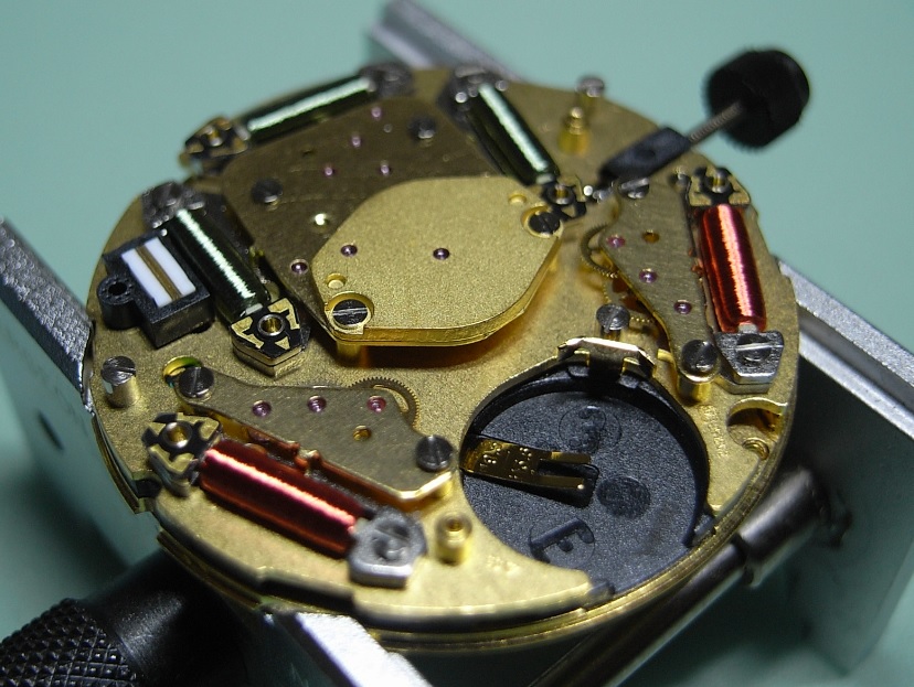
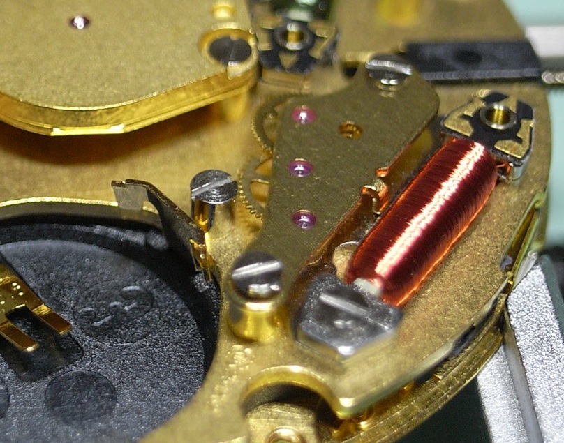
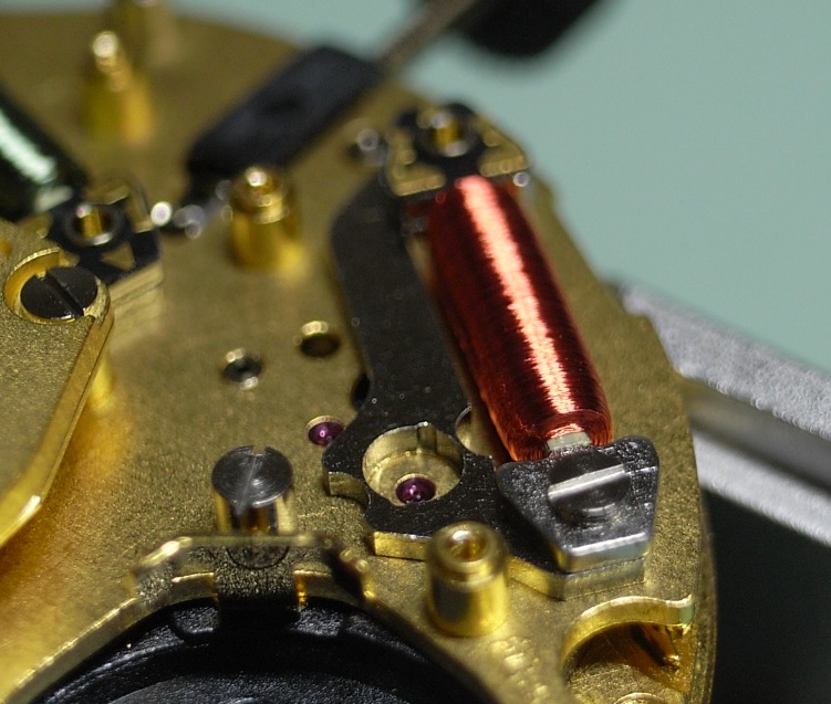
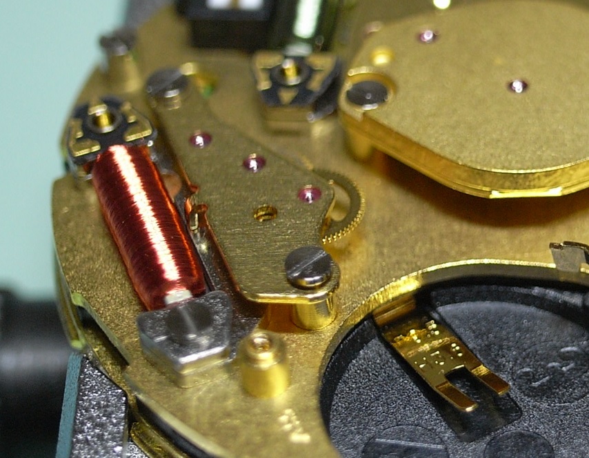
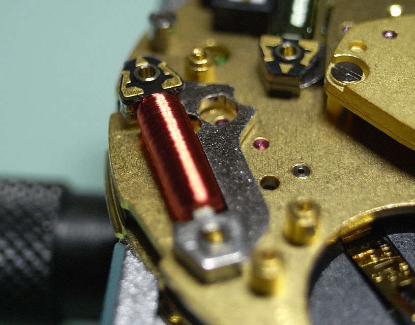
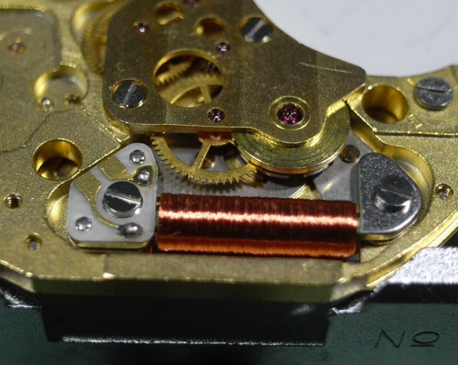
Are you sure the stud is seated correctly? It looks like it might be pointing inwards, which would cause the coil to be too close to the stud.1 point
-
Also consider a product like Microscale's Liquid Decal Film. This is a very thin liquid film that is used to strengthen decals and prevent them cracking. I've not heard of it being used in the context of lume conservation but worth a mention!1 point
-
The screw screws into the centre of the bearing so the only danger of overtightening is to break the screw! It should be tight enough to stay put but not so tight that it breaks (obvious but completely useless advice!!!) Glad to have helped.1 point
-
Hi Khan, Coil looks too close to stud so it can hit the stud upon expansion, judging by the picture, the free section of terminal curve( between regulator arm and stud) is too close to coil too. Center the coil.1 point
-
Hi V, the lantern is the holes in the opposite sides of your jacot tool. They let the pivot "hang out" while riding on another diameter. If you happen to have a set of turns you have more options.1 point
-
picked these up today
.thumb.jpg.159643d8be1afc2abd8f4e36d6567c5a.jpg)
.thumb.jpg.ca93482a584f8be9796babcb643b664b.jpg) 1 point
1 point -
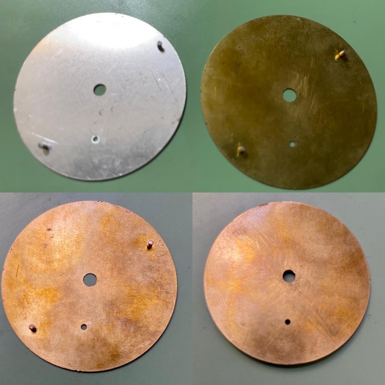
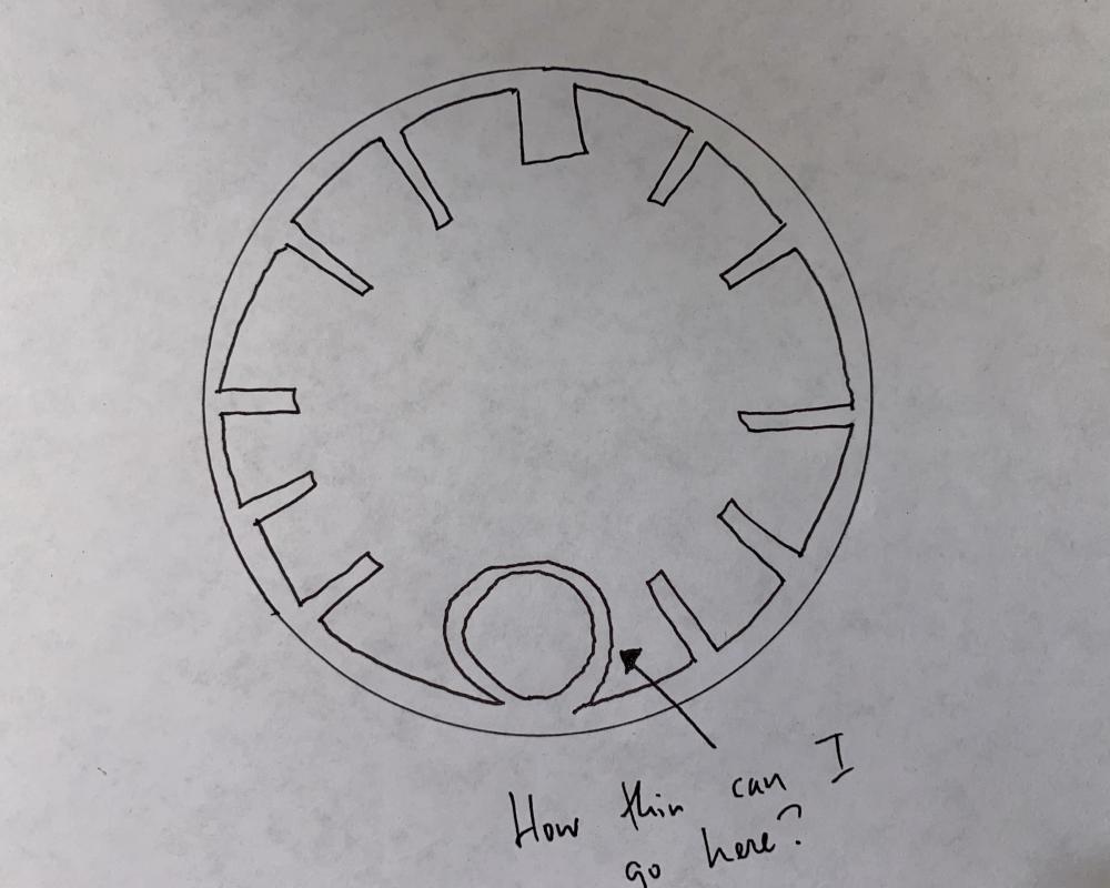
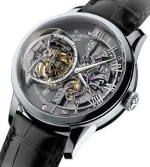
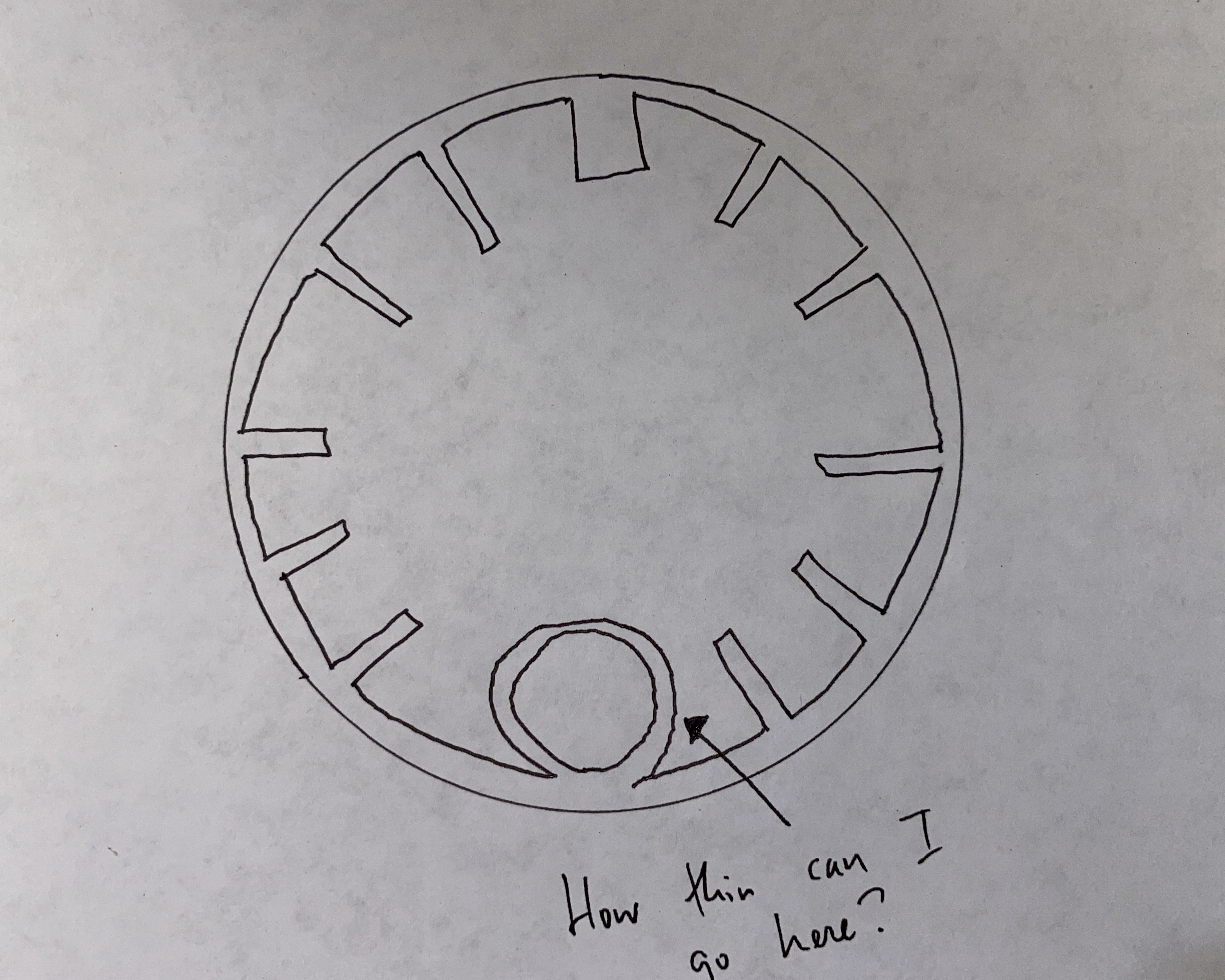
Thanks for the questions! @KlassikerThis project would not have been at all possible without the advice and good ideas from folks who were willing to share hard-won information with me. It would be disingenuous, to say the least, if I treated this information as proprietary. I've also been open with everyone who has shared information with me that it has always been my intent to document and share my process. @Nucejoe100%, the final dials have feet. I use half-height brass dial blanks (with feet) as the base for my dials, to which I attach a *very* thin veneer or fordite. I forgot one additional update: I received the prototype half-height ETA 6498-compatible dial from my Chinese supplier. It looked great -- perfect thickness, holes were in the right places and had the required dimensions, and the feet were perfect. I installed the prototype onto an ETA 6498-1 movement I had, and it functioned well. I've okayed the full production run of 200 ETA 6498 dials. Here are some shots of my prototype half-height ETA 6498 dial. The top photo shows the prototype juxtaposed against a very expensive ETA 6498 dial I have (in silver). Also, my supplier has started working on the prototype Seiko-compatible half-height blank brass dial. These will have two sets of feet, for 3 o'clock and 4 o'clock crowns. I must say that, aside from some communications issues, it has been pretty painless to work with a Chinese manufacturer here. Knock on wood! @TudorThat's fantastic advice. I have access to a grinding wheel, so I'm more than happy to buy a flappy polishing wheel and give it a go. Can you recommend a specific polishing wheel and rouge on Amazon? The specific polishing attachments I ordered for my Dremel are these: Eve Diapol Diamond Polishers @spectre6000 There's a lot of rough and semi-polished fordite available for sale on eBay and Etsy. E.g. "One Pound of Fordite Rough" here. I have found, however, that the best suppliers sell directly via Facebook groups and Instagram. I have no idea how folks are obtaining the raw material, and it probably doesn't bear close examination. I will say that the material is, in large part, attributable to specific assembly lines. Most of the stuff I've purchased has come from a Jeep / Dodge assembly line. I have a small amount from a Corvette assembly line. I've seen examples from the Harley Davidson, Peterbilt, and Cadillac assembly lines. I feel like there are body shops throughout the country that probably have thrown away tons of fordite over the years. For what it's worth, I'm *not* a car guy. I love psychedelic stuff, which is why I fell in love with the material. \\\ As for additional next steps, I'm starting to design the chapter ring for my ETA 6498 fordite dials. I've learned a lot about what the laser cutter can and can't do, and I can be a little more aggressive in this design (in terms of thinner components). My Seiko chapter rings are *very* stark and minimal -- but simultaneously chunky and primitive. I'm hoping that my ETA 6498 chapter rings are more refined and will match commonly-available handsets better.
 1 point
 -
Wristwatch? Sometimes you can gently close them with a pin vice, and a pin in the hand hole to keep it from collapsing too far. But it's fiddly work, and old hands with fragile lume in them usually don't fare well in the process.1 point
-
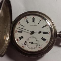
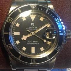
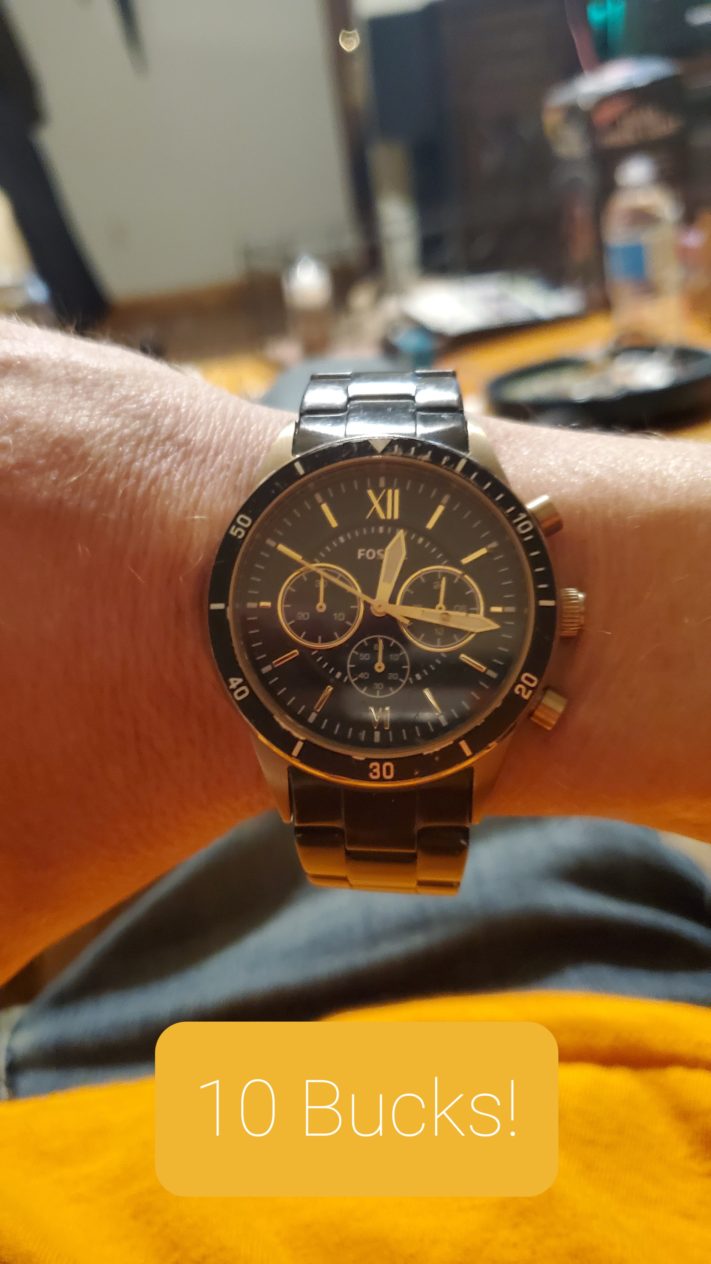
Hello everyone. Update on my kids inheritance. That's what I am telling them as I rescue these projects or I tell them these watches are investments. Like today I bought a black and gold Fossil off of FB market place. It was a pick up on the porch no interaction kinda sad situation. I walk to the closed door apartment and found the brown bag that it was pretty noticeable that its previous life was a gas station beer bag with the watch at the bottom. Pitiful it was just pitiful. The watch needs a little TLC of course what did I expect for $10. It was a pretty pitiful looking reprisation of a once perfect time keeping, shiny bezel days that it had when it was new . Well of course you know you never leave a watch behind. So I dropped the 10 bills grabbed the watch and was headed for a fresh battery. 20 mins later it was alive! So basically what I was saying was hey I got a new watch!
 1 point
 -
Well I messed up the spring even more I think I would have a better chance if it was a mens watch but hey no regrets I'm learning.1 point
-
Hi These poising calipers come in various design like the one attached below and all do the same job. That is to say determining whether a balance rim is running flat and also not out of round. Never having had to use on train wheels as yet does not mean to say that the same principal can not be used to determine the same. If and when you have to change a train wheel arbour you have to set it up as was (flat and parallel to the arbour) and in the round so as not to cause depthing problems and intermittent stoppages of the watch/Clock. I have used a home made device for checking clock wheels after pivoting and checking after mainspring breakages spinning the wheels in the lathe and monitoring its flatness and round. (964) Pinterest.html1 point
-
Thanks joe! So, that brings me back to my major question about what would be a the best or a good way to determine that all train wheels and the balance wheel are in good condition, that they don’t wobble, that the pivots are perfectly straight and so on. Based on your reply I would assume that a truing caliper is the best option for a balance wheel, but what about the train wheels, for example, an escape wheel? How can we best determine that it is perfectly straight when it comes to how the wheel rotates between its jewel bearings, that the arbor and the pivots aren't bent, etc.? I guess eyesight goes a long way, but in the realm of micro mechanics a few hundreds of a millimetre do count and I would assume aren't always visible?1 point
-
The secret to yard sales is to ask twice. The first time you ask they automatically say no. When you ask are you sure you don't have an old watch inside that is when they start to think and then they remember. I have gotten hundreds of watches that way. Got a brand new Tissot with box and papers this weekend for $40. A Zodiac last week and a vintage Movado the week before. Getting cold in Milwaukee. Yard sales will be ending soon.1 point
-
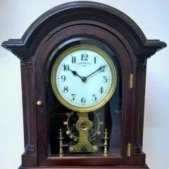
hi, many thanks for your valuable reply. i have recently restored it not fully but up to some extent keeping old ware and scratches all around! to my surprise the clock even so old started ticking after cleaning and re-fitting. it shows very precise workmanship by Corrie! the hammer strikes with full strength even after ages....pix attached. thanks/rajesh
.thumb.jpg.2268f7a09dfb01f8754f858e1e9e6e1b.jpg)
.thumb.jpg.910dad7c4671e45c80067ca600909c79.jpg) 1 point
1 point -
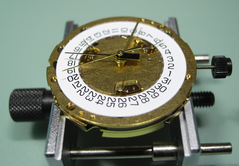
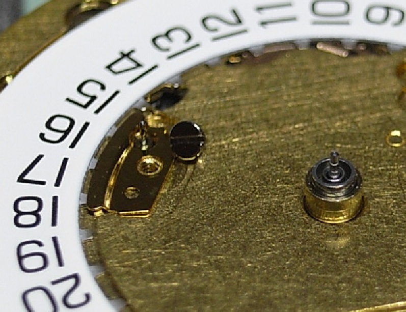
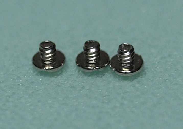
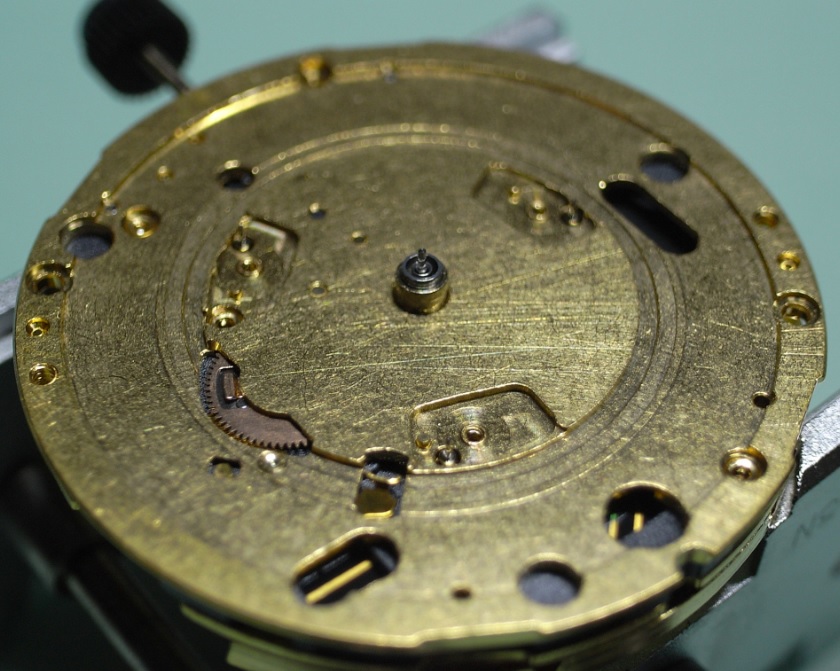
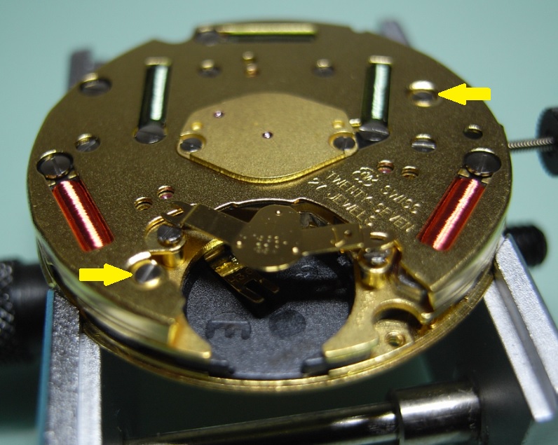
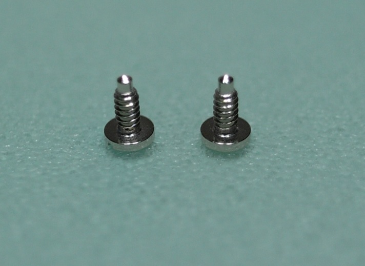
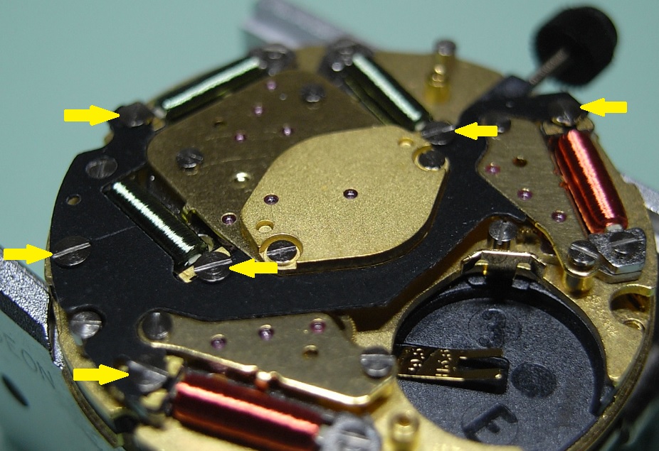
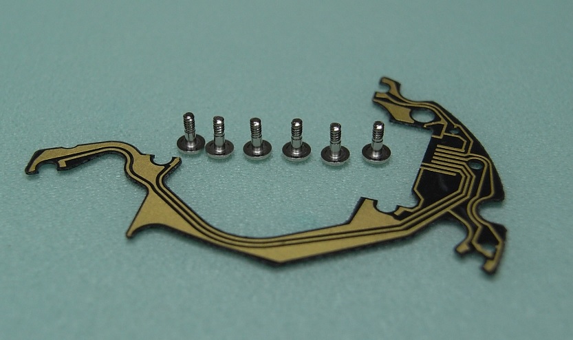
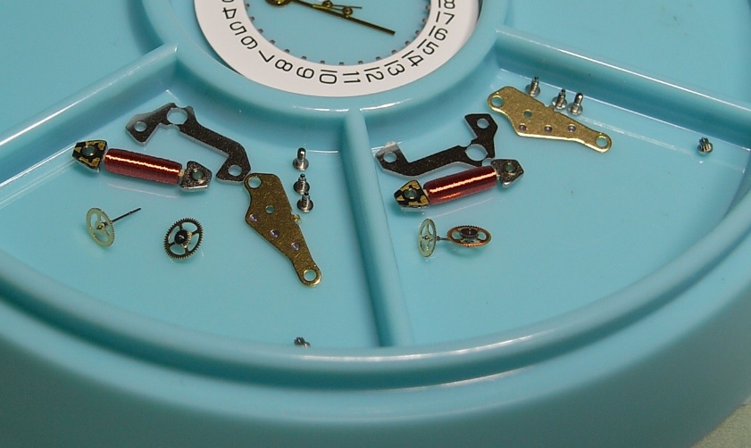
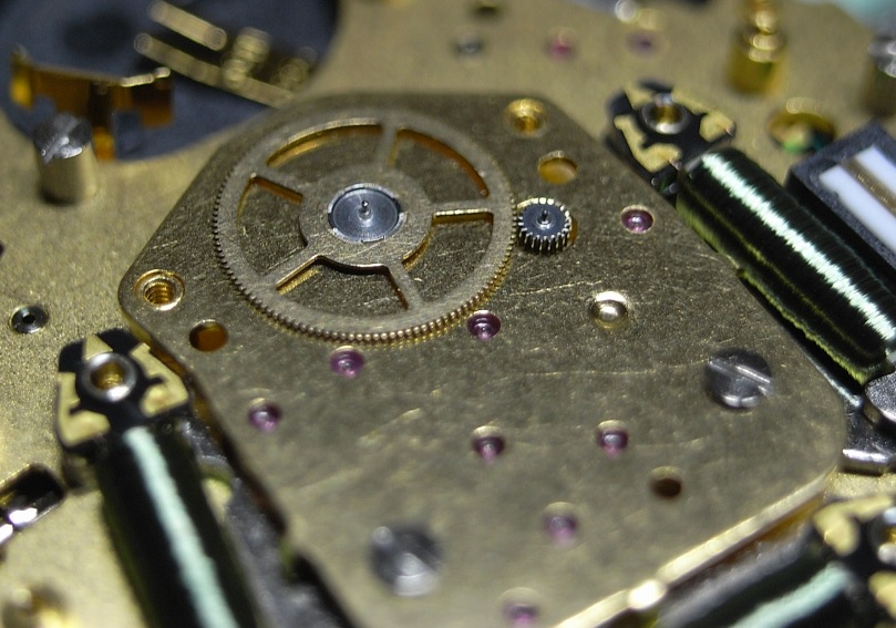
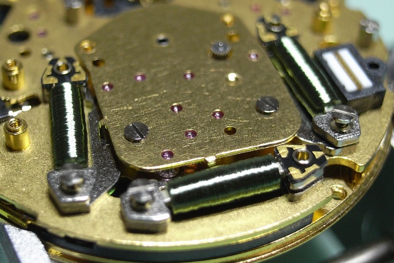
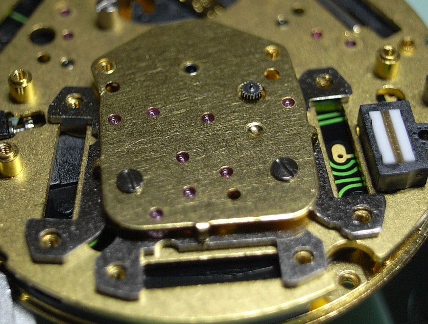
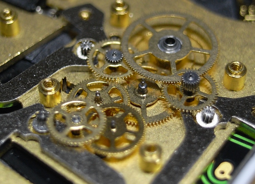
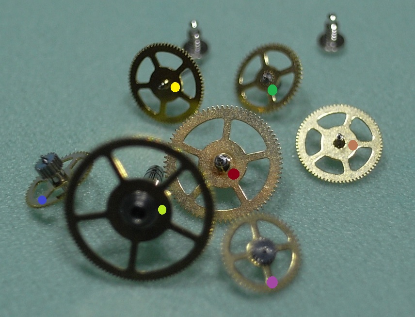
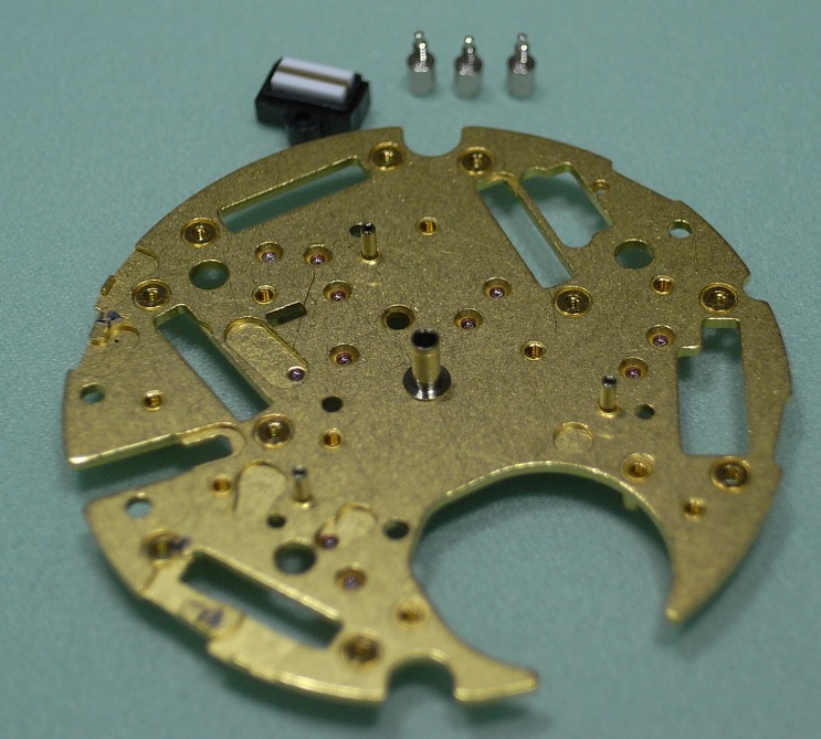
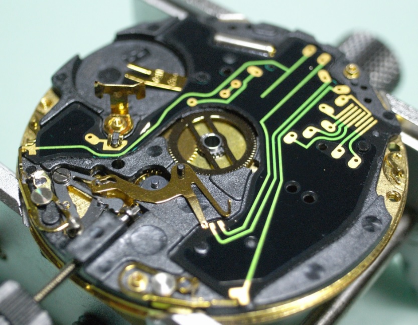
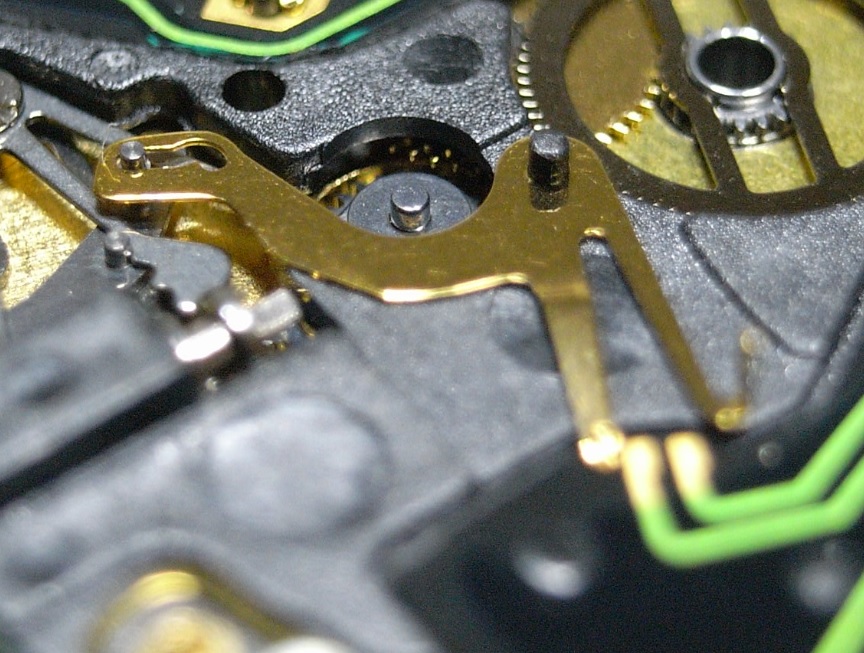
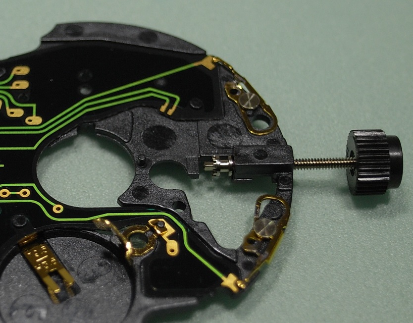
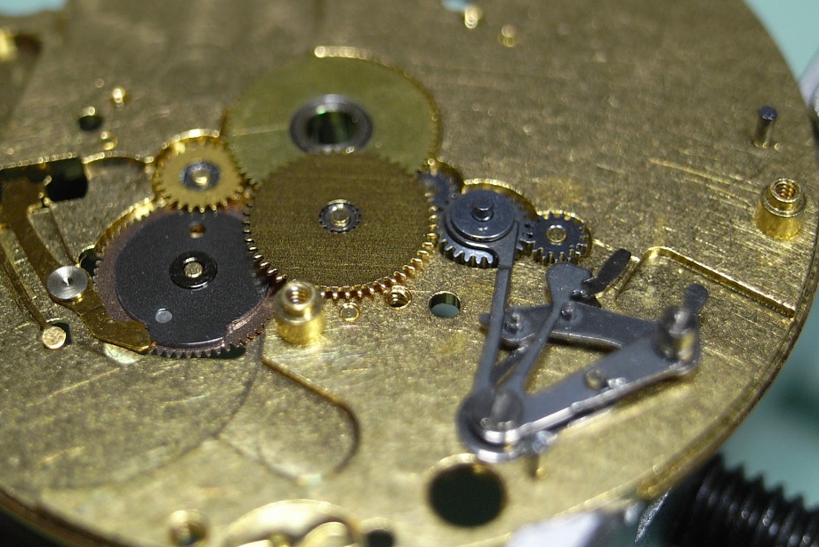
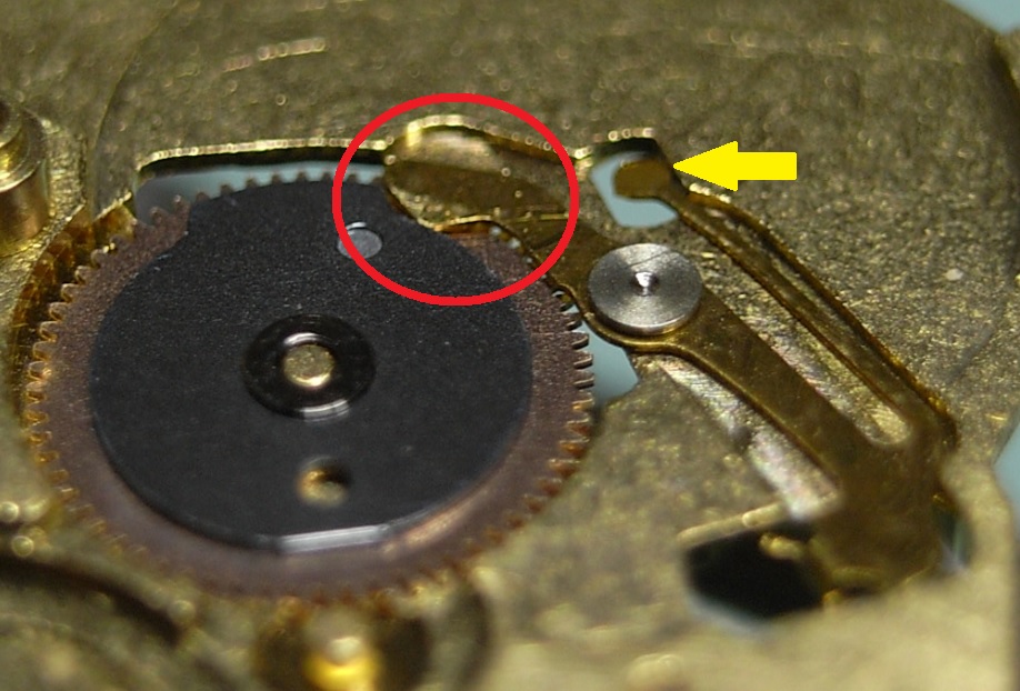
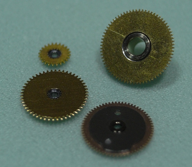
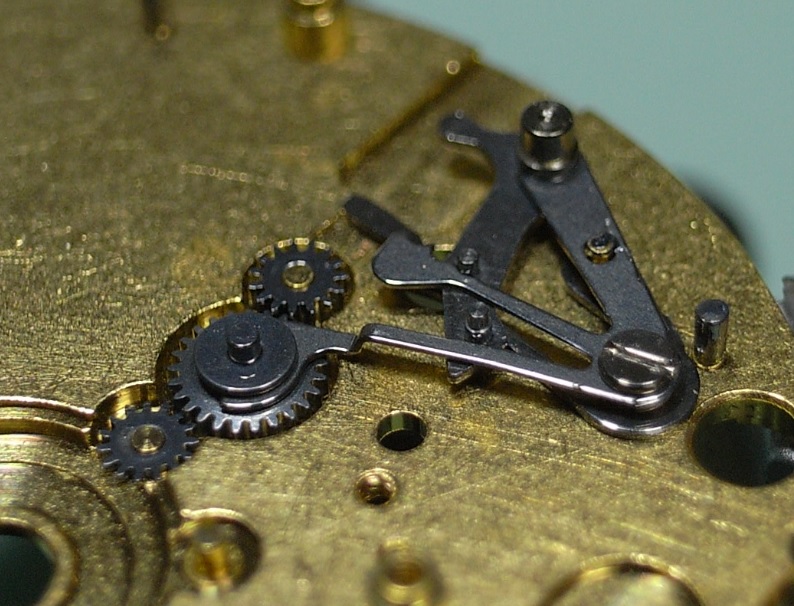
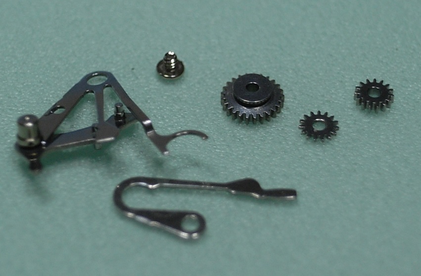
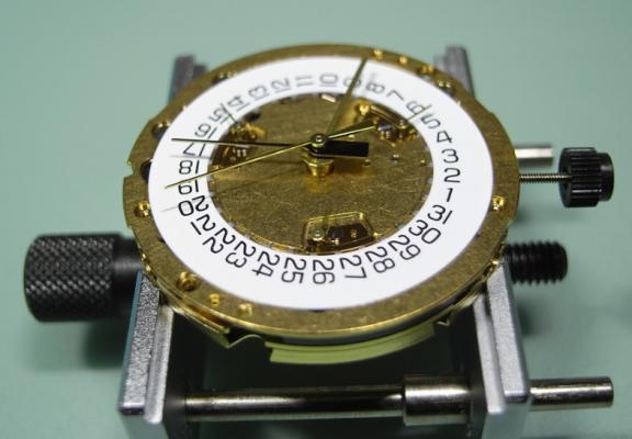
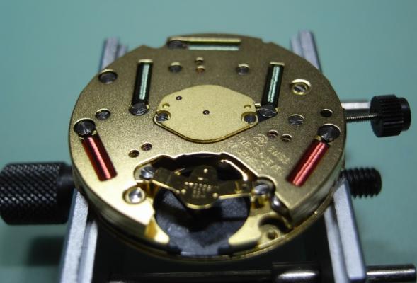
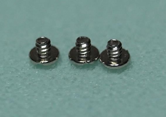
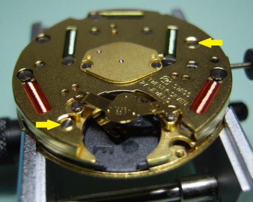
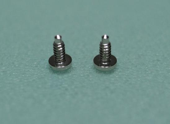
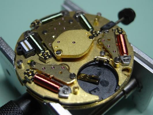
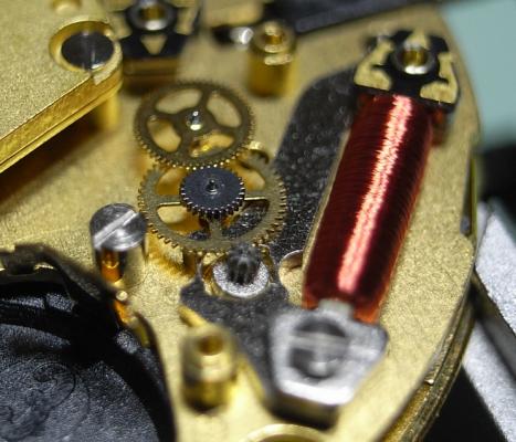
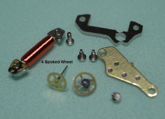
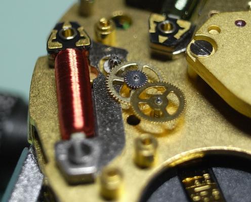
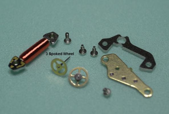
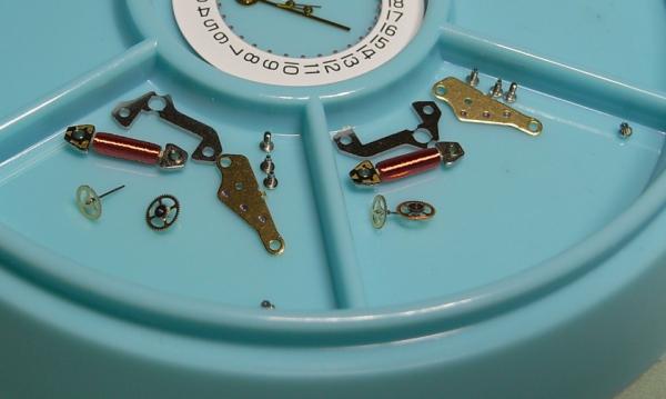
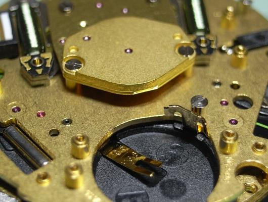
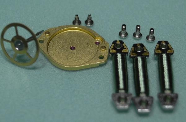
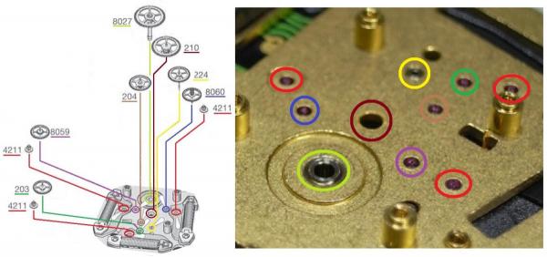
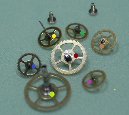
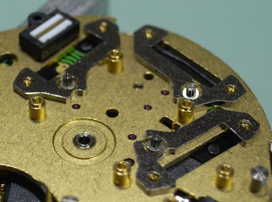
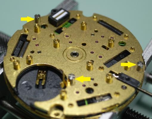
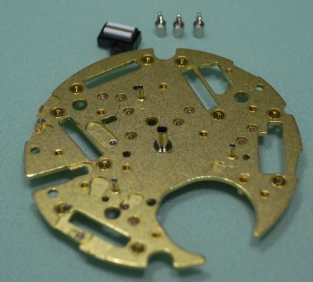
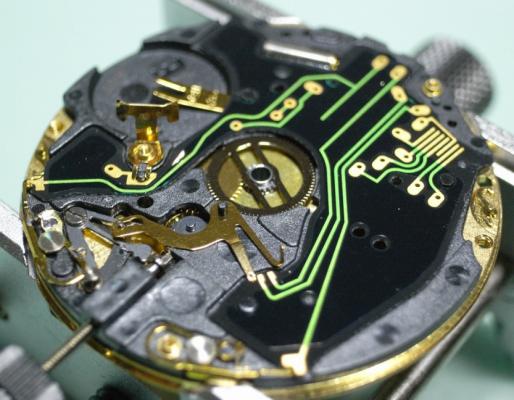
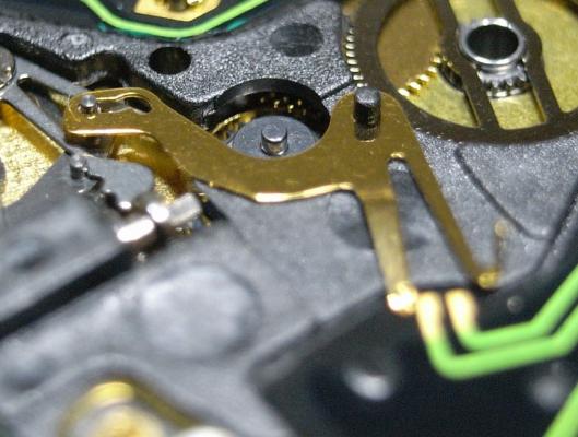
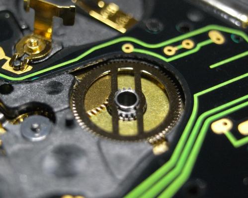
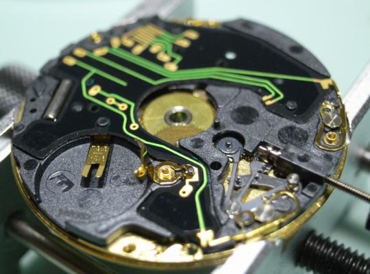
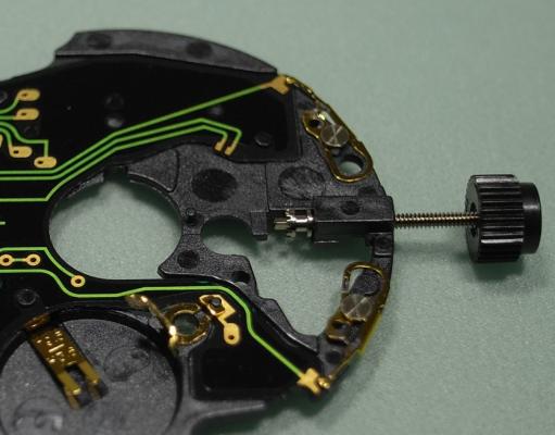
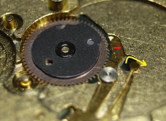
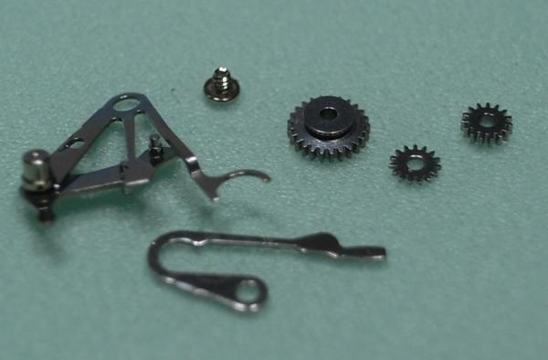
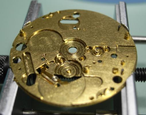
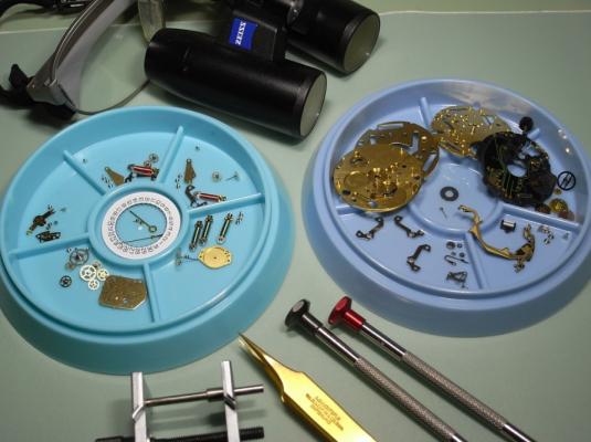
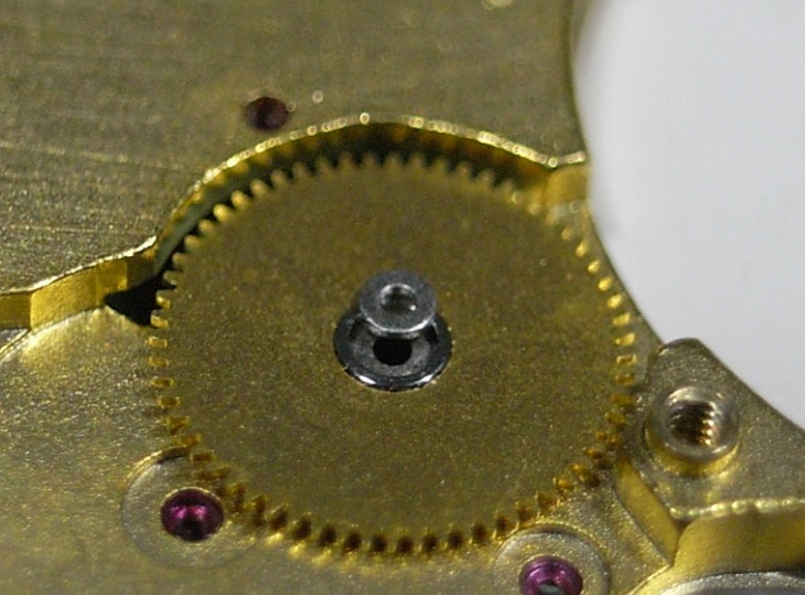
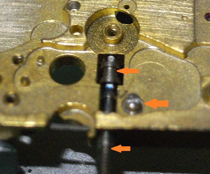
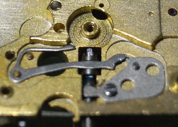
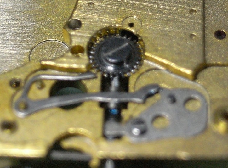
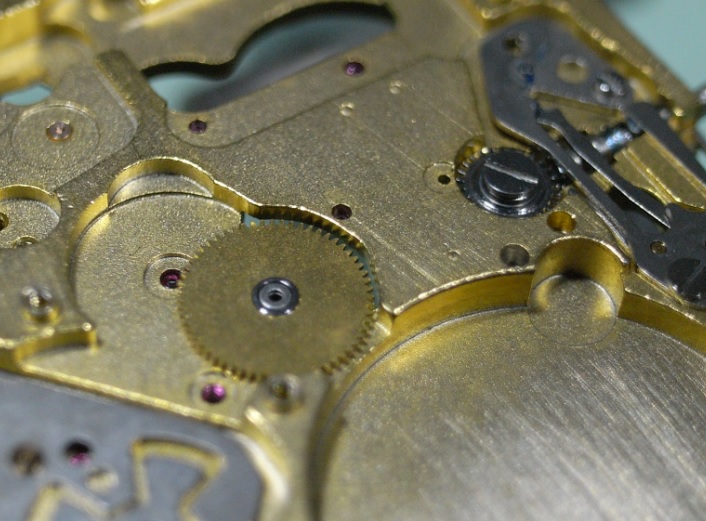
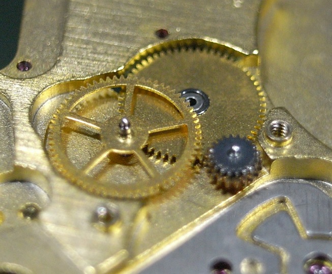
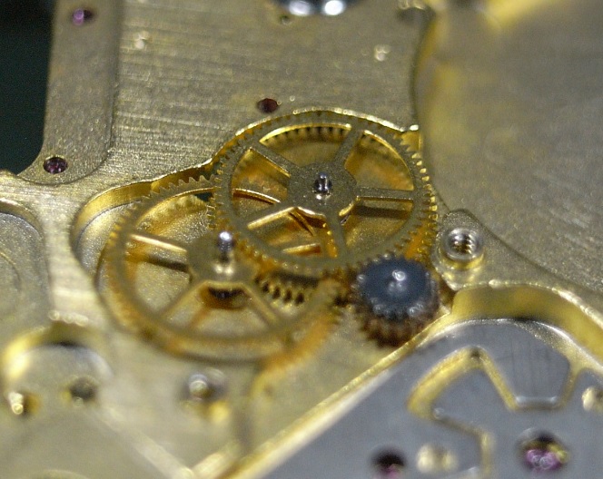
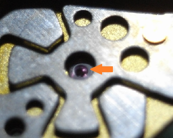
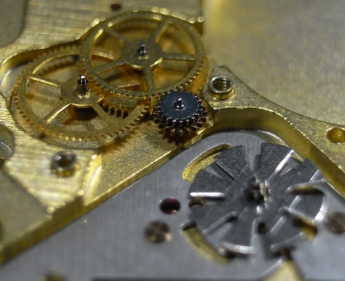
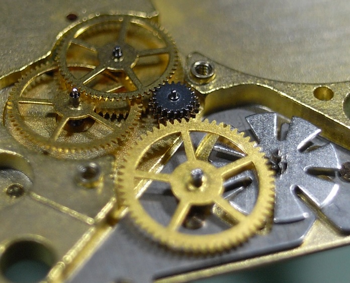
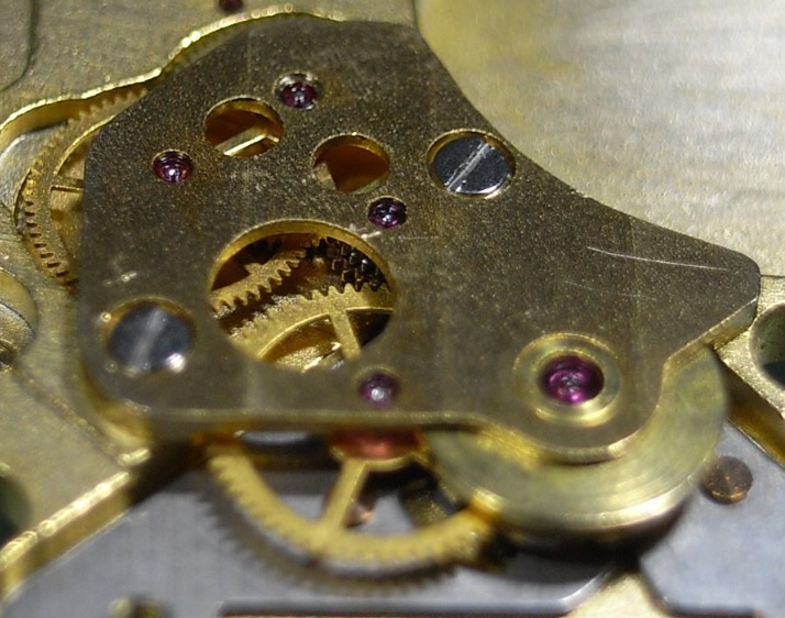
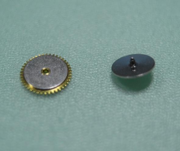
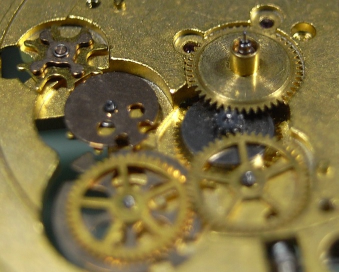
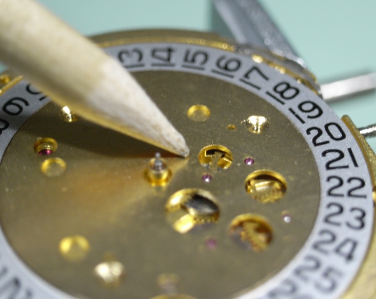
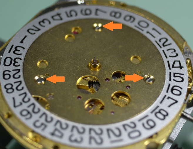
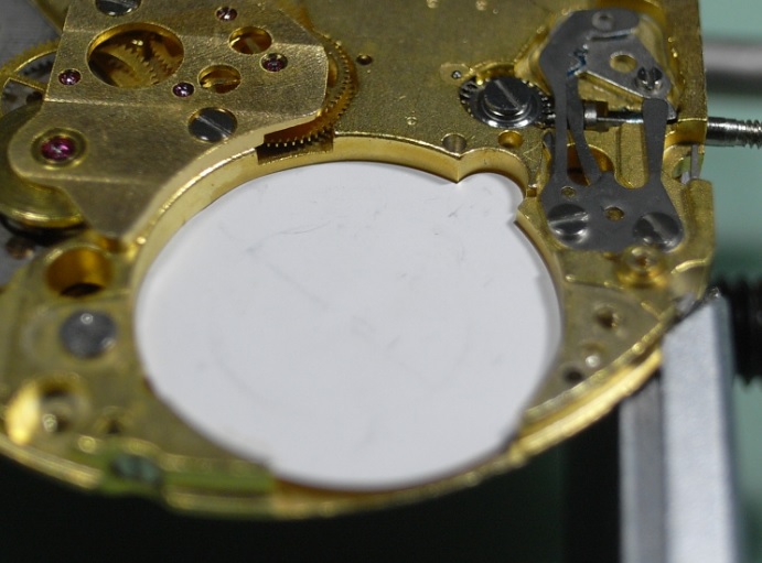
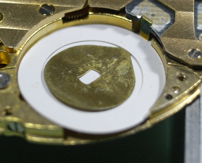
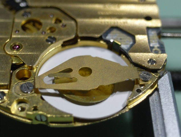
ETA 251.626 Service Walkthrough The 251.626 is often found in mid to high-end quartz chronographs on the market today. ETA 251.262.pdf It is a fairly complex quartz movement that has 5 motors, 2 with Red Coils, and 3 with Green Coils. To begin the service we start by removing the 3 Indicator Maintaining Small Plates, and Date Indicator. A 1.4mm screwdriver is all the is needed for every screw on the movement. Here's a reference photo of the 3 screws for the Indicator Maintaining Small Plates. There are no more components to remove from the dial side of the movement. Once the movement is turned over, remove the 2 screws that hold the Magnetic Screen. Once the Magnetic Screen is removed all the coils are very exposed, so work around these coils with great care. Here's a reference photo of the 2 screws for the Magnetic Screen. Next unscrew the 6 screws holding the Additional Printed Circuit and gently lift it off the movement. Store the Additional Printed Circuit away separately and safe from the rest of the parts. Here's a reference photo of the 6 screws for the Additional Printed Circuit. Next we tackle the 2 trains with the red coils. Right Side - Minute Counter Left Side - Hour Counter The right and left trains contain different size wheels and should be kept separate for ease of assembly. We shall start with the right side. Remove the Minute Counter Bridge Next remove the Gear Train and the Rotor. Next remove the Coil and Stator. Store the Coil away separately and safe from the rest of the parts. Here's a reference photo of the components and their corosponding screws. Note the 4 spokes on the Minute Counting Wheel. Remove the Hour Counter Bridge. Remove the Gear Train and the Rotor. Remove the Coil and Stator. Store the Coil away separately and safe from the rest of the parts. Here's a reference photo of the components. Note the 3 spokes on the Hour Counting Wheel. Store these 2 trains in separate sections in your parts tray, and when cleaning store them in sparate parts containers. Next remove the Chronograph Bridge Now remove the Chronograph Wheel Unscrew the Green Coils and remove them. Store the Coils away separately and safe from the rest of the parts. Here's a reference photo of the components and their corresponding screws. Remove the Train Wheel Bridge. Remove the Wheels of the Train. This is quite a complex train of wheels. So to assist you I've cleaned up the rather cluttered schematic supplied by ETA and colour coded each wheel and it's location on the Main Plate. Here's a reference photo of the top of the wheels, also colour coded to assist you. And also the underneath of the wheels, also colour coded to assist you. Remove the Rotors and Stators. Unscrew the 3 screws that hold the Upper Plate and remove it. Here's a reference photo of the Upper Plate, Connector, and the corosponding screws. This now exposes the Electronic Module. Remove the Stop Lever/Switch Remove the Cannon Pinion with Driver. Then remove the Electronic Module. Pull out the Stem and Sliding Pinion. Now store the Electronic Module away separately and safe from the rest of the parts. Remove the Minute Wheel, the Hour Wheel, and Contact Intermediate Wheel. Before we can remove the Date Indicator Driving Wheel, we need to pull back the Date Jumper. Gently lift the tab (Yellow Arrow) until it's at plate level and pull it backwards. This will pull the arm of the Date Jumper back and allow you to remove the wheel. Here's a reference photo of the wheels. Lastly we need to remove the keyless work. Unscrew the Setting Lever Spring and then remove the Setting Lever, Yoke, Driving Wheel, Internediate Setting Wheel No.1, and the Setting Wheel Here's a reference photo of the Keyless Work. The movement is now completely disassembled. I hope you've enjoyed this disassembly walkthrough and found it's given you the information and confidence to tackle this tricky but rewarding quartz movement. I will post the assembly procedures tomorrow, Lord willing :)


 1 point
 -
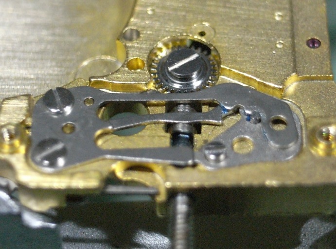
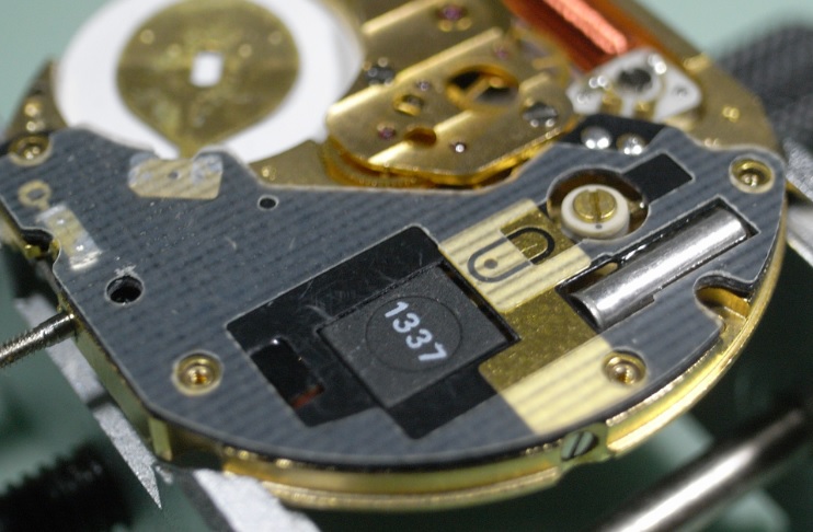
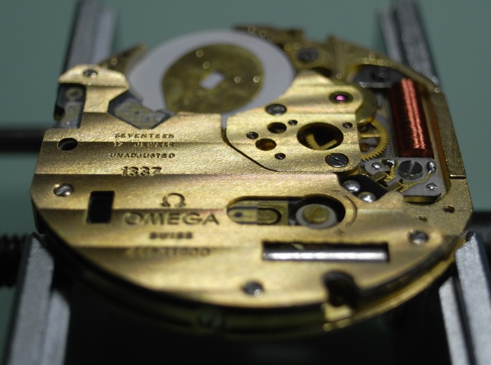
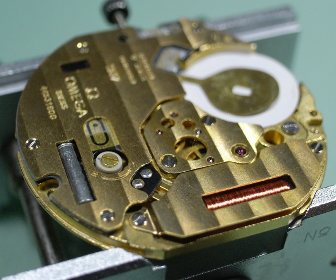
Unfortunately I do not have an exploded diagram of this movement, with the correct terminology for the parts or the factory oiling procedures. The following is my own procedure for assembly, and I will leave the oiling to your own discretion. Personally I used Moebius Quartz Oil and Moebius 9501 for the Keyless Work. If anyone has a copy of the 1337 Technical Document please upload it to assist others. Assembly I started with the Keyless Work... Lubricate the Stem and install the Sliding Pinion and Stem. Also screw in the Setting Lever Screw. Install the Yoke and place the arm into the slot in the Sliding Pinion, and replace the Setting Lever. Install the Setting Wheel and fasten down. The last part of the Keyless Work to be installed is the Setting Lever Spring. Next install the train... Install the Minute Wheel, being sure to replace the small washer. Install the Intermediate Wheel and the Second Wheel Driving Pinion. Next install the Second Wheel. The lower jewel for Rotor is a blind pivot point, this needs to be lubricated BEFORE installing the Rotor. Install the Rotor. And lastly install the Third Wheel. Carefully install the Train Bridge, be careful to check the free running of the train before tightening fully. Next flip the movement over and proceed to install the Motion and Calendar Work. Firstly make sure the Magnetic Friction Wheels (Cannon Pinion) are very clean. Especially the flat plates between the wheels. Install the Magnetic Friction Wheels (Cannon Pinion) Then install the Calendar Setting Wheel. Next install the Motion Work Setting Wheel. Install the Intermediate Date Wheel. Lastly is the Date Indicator Driving Wheel and the Hour Wheel. Now all the wheels are installed you have to time the Calendar Setting Wheel, Intermediate Date Wheel, and Date Indicator Driving Wheel. This will take some study to setup correctly without the documentation; but take your time and you'll find it will become obvious how these wheels interact with each other. Once you have set the timing up, replace the Calendar Ring and Date Indicator Maintaining Plate. Then gently hold the plate down with a piece of Pegwood, and with the Crown in the second position, work the wheels and test that the pivots are located in their jewels and the timing of the Calendar Work is correct. Once you are completely satisfied that everything is working as intended, screw down the plate. Flip the movement over again and replace the Battery Insulator. Install the Coil. Install the Circuit and Circuit Insulator. Replace the Electronic Module Cover. Next replace the Coil Protector. Install the Battery Insulating Ring. Install the Battery Clamp. Please Note: The Battery for this movement is the 391/381. Lastly install the Dial and Hands. This completes the assembly of the Omega 1337 Movement. I hope this walkthrough gives you the confidence, steps and reference photos to tackle this movement yourself.
 1 point
 -
When I prescribed drops of penetrating oil, I mean't watchmaker sized drops, not locomotive engineer drops. Put a bit of oil into a small container (egg cup, teaspoon etc) and use a safety pin dipped in the oil to apply the drops to six points around the caseback. The oil will wick along the threads and shouldn't actually seep into the case if done in moderation.1 point
-
If he broke a jaxa wrench then that ball won't be much use except for a game of squash [emoji6]1 point

.jpg.a5bd3efa1a84acb6ccfa6da4646e5c4f.jpg)
.jpg.fc9d312d7cfb40aa70235d702b07a5f3.jpg)
.jpg.cca3107c7235505ded0e9fa167e8a8c0.jpg)


.jpg.ac8148f153a322a4b8fdc7cdaf85460a.jpg)
.jpg.237eab742df16bba0bd11e3389bd1863.jpg)


.jpg.c01654591f13a1c02266330f288b01a9.jpg)
.jpg.98d393673e2df10699ea668525929fc4.jpg)