Leaderboard


Popular Content
Showing content with the highest reputation on 01/18/20 in all areas
-
Smith's just serviced.
 2 points
 -
For further clarification, Yes, it is exactly where it says “Push”, but also you have to pull out the winding stem to the first position, before there is anything to actually “Push” on. If you look into the space where you have to push, you will see the setting lever move into the correct place to be pushed, when the stem is pulled out to the first position.2 points
-
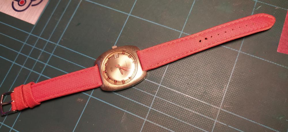
Hi If you are going to replace the mineral crystal with an acrylic one without the gasket it is possible but you will need to measure the case seating of the watch and what ever the measurement is add 0.01 but you will need a claw insertion tool and pick up table to do that and also probably some glue/sealant to put round the case, Usually somthing like Minicol UV curing cement to ensure water resistance. May I ask what is the reason for the change as the minerals are harder and scratch resistant, acrylics pick up lots of marks but they can be polished out in in most cases.2 points
-
Hi guys … I had promised that I would make a « custom decal dial tutorial » on another thread there So here we are … There are many variations of decal dials, the best IMHO being the « negative gilt » dials which gives the best results. The process I’m showing today is aabout how to make a dial with black printings on a one color background. I had a cheap quartz diver waiting in my drawers so I’ll make a Heuer diver hommage based on the 980.016 model (quartz one too). DAY 01 : It’s 4:30 AM (I’m an early bird) and I have 2 hours to kill before a business trip to Paris (I’m French) so I decide I have time enough to begin. The first part of the process is to prepare the dial plate : - stripped it, removing all the lumes bars and dots - soaked the dial for some minutes in acetone to remove the paint - filled the tiny holes where the bars and dots go with cyanolite glue - sand everything flat I sand with 800 and don’t try to get a smooth surface as I want the paint to adhere perfectly to thedial plate. Here is the result … Then I want to spray paint. I make a tube with some painter’s tape, from a « curve » with it and place it on a plastic bottle cap. I want it curved so that I can stick the dial on it without any risk of bstructing the center hole or the date window of the dial plate. So I stick the sanded dial plate on the tape tube. As you can guess from the pic below … that’s not the first time a make an orange dial. Then I place the bottle cap and dial plate on a paper sheet and spray paint in orange. I use street art spray paint as it is « water resistant ». As you can see on the next pic, I don’t try to get a smooth surface, or even to perfectly cover the dial plate at first. I will let this coat dry, sand it with 2000 grade, then spray 1 or 2 coats until I get a perfectly smooth orange dial plate, ready for receiving a decal. So I place the bottle cap and dial under a shooter glass and will let it dry for about 24 hours before sanding and spraying the second paint coat. The 24 hours drying time is really important (though it could depend on the paint you use). The paint I use looks perfectly dry after about 5 hours but if you spray the second coat without waiting enough, that coat won’t perfectly adhere to the first and you could get a granular surface like an orange peel. And here is the dial waiting under the shooter glass. On the right is a « negative gilt » dial (third and last matte varnish coat) On the background there are two Raketa 2609 movements from the 70ies, quietly (really loudly to be honest) ticking for test after I‘ve recently serviced them. Now it’s 5:45 AM so I will have a and go to the train station. I’ll sand the dial plate this evening and spray the second paint coat tomorrow morning. Then sand it in the evening and spray the third coat (if needed) the day after. DAY 02 - DAY 03 : So here's what you get after the first paint coat … doesn't look really good but no matter as there's still some work to do to get a better result. And here's what you get after 3 coats of paint, each one sanded with 2000 grade, to get a perfect finish, flat and smooth. Now the dial plate is eady to receive the decal. DAY 03 : I won’t explain anything about Photoshop and Illustrator here … I’ll only explain how I print my decals. One thing really important, from my own experience, is the definition of the design. I’ve tried several, from 1200ppp to 6000pp and the best results I’ve got on printing decal sheets were with a 4000ppp definition. So all my dial designs are done in 4000ppp. The result is really BIG files … for example an A6 template with 12 dial desings ready to print is about 800Mo. As that dial is black printing only I open it with Photoshop and let the softwre (so ont the printer) deal with the printing quality. My printer is an old Epson Picturemate with a 1200 maximum definition. As the good quality decal sheets are not cheap and as I’m a « skinflint» I often print on A7 sheets … 6 dial designs on one sheet. When printed you should let it dry for about 4 hours then spray 2 really thin coats of matte varnish, letting each coat dry for at least 12 hours (24 hours is better). DAY 04 - DAY 05 : 2 days of speed-hiking with my wife so I didn’t worked on that tuto. You can check on the net what speed-hiking is, but to summarize it’s hiking as fast as you can with really light backpacks, trying not to run (or only short runs). On a good day you can walk 5 to 6 miles/hour … when trained you can walk up to 6,5 miles/hour … and while I trained for my first 62 miles ultra I achieved to walk (no running) up to 6,85 miles/hour (11 km/heure). DAY 06 : Today is Monday 6:00 AM. It’s been 5 days since I begun that tutorial and … my legs ache and all my body is painful (see Day 04 - Day 05) The dial plate is ready and the decal sheet too. You can see that the decal sheet looks matte now. That is because I have sprayed 2 coats of matte varnish on it, to protect the inkjet ink while I’ll soak the decal in water. Of course if you print with a laser you won’t have to spray varnish as the laser inks are (almost) water resistant. First thing to do is to chose the best item on the decal sheet and cut it round. Then you are ready to go. On the next pic you can see all you need now : - dial plate … fixed on a foam board using the dial feets - decal dial … nicely cut round - tweezers - thin and smooth brush (mine’s a watercolor brush) - some « micro set » … or just vhite wine vinegar (it helps the decal to set on the dial plate) - cold water Now you put the decal in cold water and while it soaks you brush some micro-set (or white vinegar) on the dial plate. Then you put the decal on the dial plate. Here you can see why I prefer using clear decal sheets on coloured dial plates … because it’s much easier to « perfectly » positionate the decal, using the central hole and the date-window. When you’re happy with the position of your decal you use a paper tissue to absorb the excess of water. Do that carefully as you don’t want to move the decal on the plate. And here we are … everything worked fine while absorbing the water and the decal position is OK. I’ll let it dry for about 12 hours before I cut the central hole and the date window, before I proceed to the varnish finish. Still Day 06 but 7:00 PM The decal has dried for about 13 hours so now I can proceed on cutting the decal sheet That's what I do then I : - fix it back on the foam board - apply some « micro set » around the center hole, the date-window and the outer diameter - gently press with a paper tissue so that the decal is perfectly applied (no more «air bubbles) And I let dry for 3 hours more Evening … 10:00 PM Now the decal is « perfectly » applied and dried and ready for the finish Last pic for today is after spraying the first coat of glossy varnish I will let it dry for 12 hours, sand it with 2000 grade paper and apply the 2nd coat. DAY 07 : 20:00 AM … only 1 pic today just after finely sanding with 2000 grade the 2nd varnish coat I applied yesterday DAY 08 : Yesterday evening I applied the 3rd and final varnish coat after finelt sanding and cleaning And today I can show you the final result … and say I'm pretty happy That dial is so glossy it’not easy to get a good pic, even on close-up. May I say that me hpone is nit the best at shooting pics (just like me) and the actual dial is much much better that it looks on the pictures below. I hope that you liked that tutorial and that it could be helpfull to members who want to try to build their own watch dials. I’ll try to make better pics with a real camera and a better lens … next week of the week after, after luming the dial together with the hands. Then I will still have to get a case and rework it so that it could be a 980,016 lookalike. Some of you may wonder how much time did I spend to make that dial. It took 8 days to achieve the all process but I spent only 1 hour the first day then only from 15mnm to 5mn the days after. So, apart from the design work on Illustrator and Photoshop (which took me hours), I would say that the whole process is about 2 to 3 hours. I must say that it's not my first try at dial making and I've trained for 2 years now. So if you want to try you should consider spending a few more hours but it's really worth the time spent as at the end you get your unique DIY dial.1 point
-
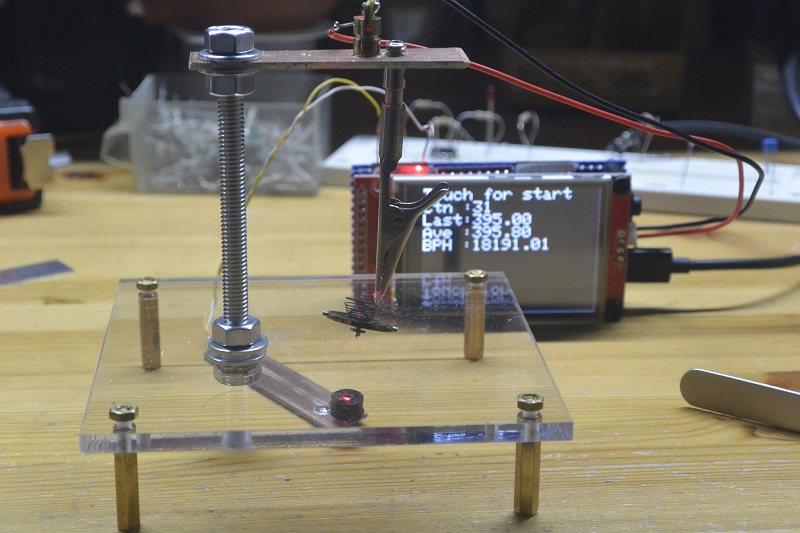
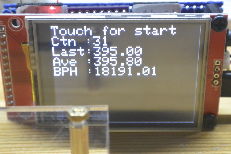
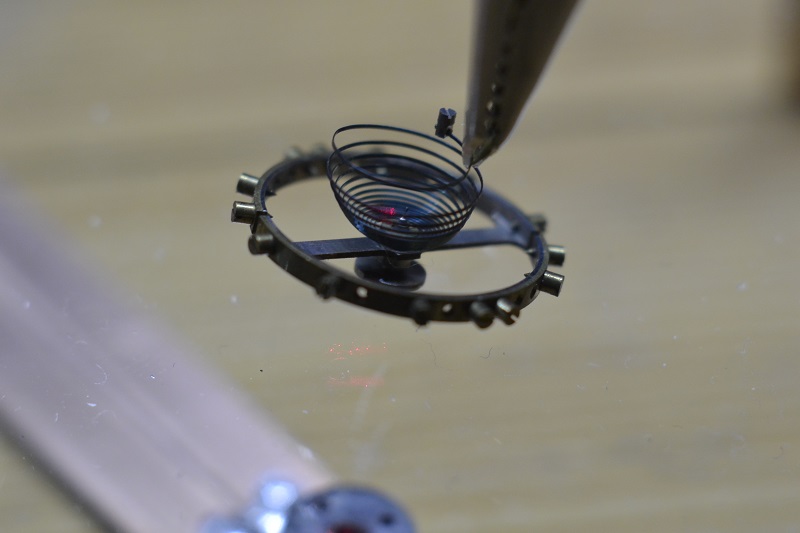
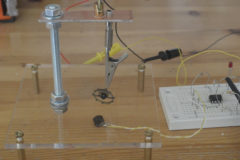
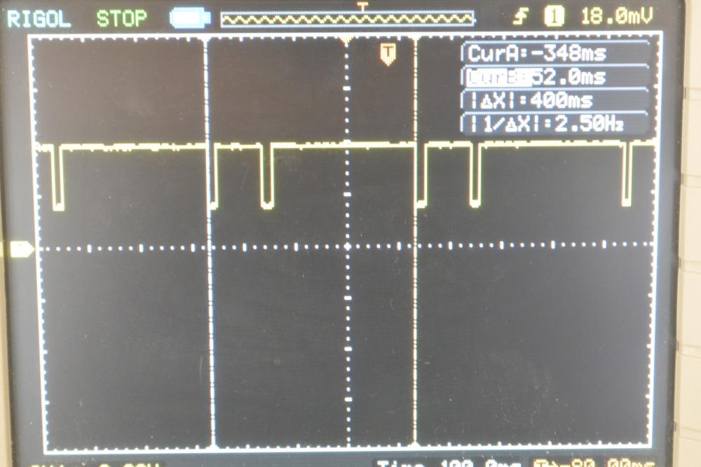
Hello guys, An attempt to make a low cost hairspring vibrating tool : Prove of concept : The hairspring (here it's a 18s balance) is clamp in a crocodile clip which has been grinded to be as fine as possible, a laser beam is set so that the beam is cut by the balance arm. The photo diode (from an old pc mouse ) is en-capsuled in a little housing to avoid parasite light (from what i thing to be an old TO3 transistor spacer found in my spare screws box). The IC is just a simple op amp acting as a comparator, the led on the output is used to visualize the that the laser beam is on the detector. First measure on scope : Doing some simple math show that an error of 0.1 ms on the measured value (which is 400 ms for 18000 bph) correspond to an error of 21.5 seconds / day. At that time base setting my scope has a resolution of 4 ms ! I switched to an Arduino based measuring system : I used an existing Arduino module based on a cheap stm32 and add a led (indispensable to adjust the beam) and the power output for the laser. The comparator is no more required as the stm32 has schmitt trigger inputs. The soft is triggered by the touch screen and accumulate a couple of measures in a circular buffer to compute an average value. This permits to eliminate aberrant measures that you can have when the balance starts to swing. Detail of the crocodile clip : In conclusion this is little tool (cost me only the plexyglass sheet, around $1.5) could be useful to match a new hairspring on an existing balance. The measures are relatively simple to do with a good consistency and surprisingly the croco clip do the job and you can get the balance swing for tens of second on the plexy. You need a resolution of 0.05 ms to be at 10 s/d and probably calibrate your measuring device. The main difficulty was to adjust the position of the laser beam. Hope this can give you some ideas. Regards
 1 point
 -
Having been repairing clocks for some years, I was told by my wife that watches take up a lot less room, so I have graduated? downsized? to watches. Have been doing it for a couple of years, my main interest is vintage mechanical but now trying kinetic. Watches, parts etc sourced mainly from eBay and learning all the time from YouTube videos. My main problems are hairsprings, and cat hairs from our two resident mogg (oops, will be in trouble now ) non-moggy cats.1 point
-
I'm guessing that he simply doesn't know how to put it back together. Should have taken photos of the process, it helps a lot.1 point
-
I agree with Chopin and jdm, With insufficient data we cannot work miracles. as stated we need photographs of the rear of the watch and backplate also the front plate and any writing that is on the back plate to be able to identify it. Depending on the state its in now may be a replacement movement will be in order and without the data we cannot proceed.1 point
-
I would be glad to help but its best if you submit your photos on here so anyone in the community can share their thoughts on your issue.1 point
-
Welcome here. I am bit intimidated by CNC and machining in general myself, but after tinkering with my micro lathe I've found that is not much different from working on watches, time flies, little is accomplished, and more tools are always needed.1 point
-
Post some photos of your problem ?1 point
-
Would need more and better photos. At first glance that looks like a redial. Crown is a replacement ? Seems slightly different in color than the case and possibly bigger than what it should be. What about the hands ? Wouldn't be surprised if those are non-genuine either. I don't know the movement so can't tell about that one. Seems alright but we'd need to compare it to others... The case clamps are installed wrong. They should go inside the case so to speak which is actually a retaining ring that can come out with the whole movement I believe.1 point
-
Yep I have seen them pics too. I have tried all sizes of Trior ie Kif 1-3, 1-4, 1-5. neither of them fit. The spring that was mangled in the stem was a Duofix. Maybe a previous repairer had fitted the wrong spring hence why it has fallen out. This afternoon I have managed to modify a incabloc spring which fits (just) and the watch is now on test. I did try and modify a Trior by putting a curve in it using my staking tool as if you look at the pics the springs are not flat. This did not work either. What fun!!! Just noticed whilst studying the pics is they are not Trior. They are very similar but not Trior. What they are I will have to investigate.1 point
-
Cats..I am allergic , I like them, but I like breathing more . Dogs are more to my liking ,I see in them all the virtues we call human but are too ashamed to admit we learned from them.1 point
-
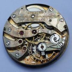
jdm has saved me from writing up. Just to say that hairspring is in a right old mess.1 point
-
First, the hairsping in the picture is unacceptably distorted, many topics on the subject of correcting an HS and the difficulty of the task - high. If you want to show how an HS looks like, remove cock, lay it down and shoot from above. Then, fault finding consist of taking the entire mov't apart, clean it the best possible, inspect every part under magnification, pivots, jewel, gear teeth for damage. Put it back in the most basic form and test every function, end shake of every wheel etc. You can do that even without oiling because it will run anyway, not perfectly but it must not stop. Again, the forum has many many repetitive threads, which will tell you always the same things, just as any book would.1 point
-
Just like many Japanese, and ETA quartz as well, it's exactly where one expects it to be, and there is an harrows that points to it, written PUSH.1 point
-
This subject has previously been covered, use search function to find the relevent thread. Regards1 point
-
No gasket. Measure the rebate dimension and fit the next size up. You should be able to press it in without using a claw.1 point
-
1 point