Leaderboard


Popular Content
Showing content with the highest reputation on 03/01/17 in Posts
-
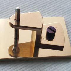
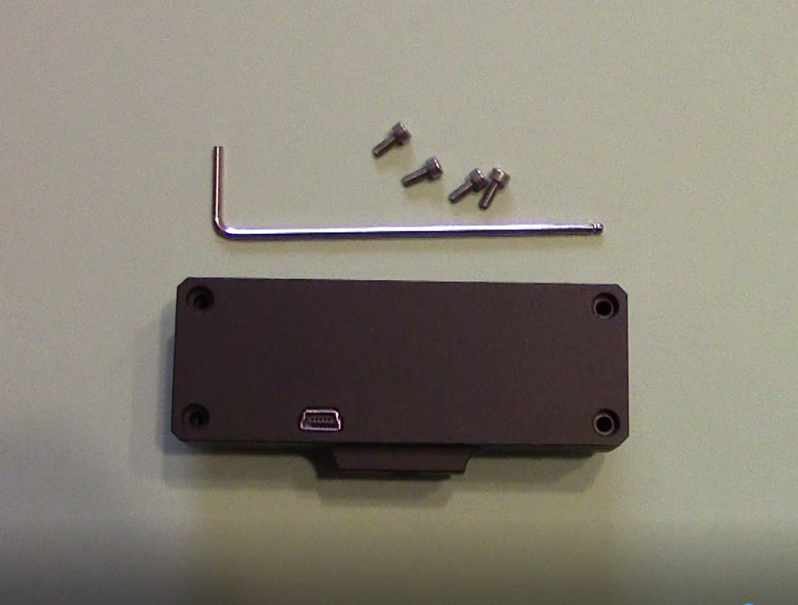
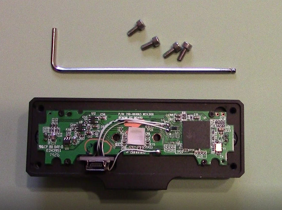
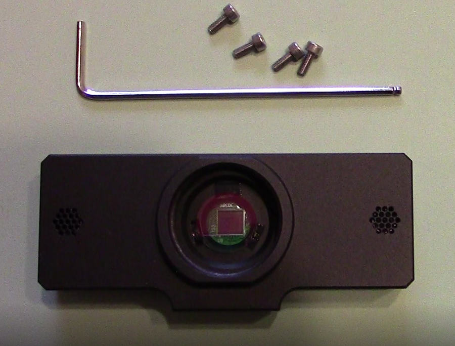
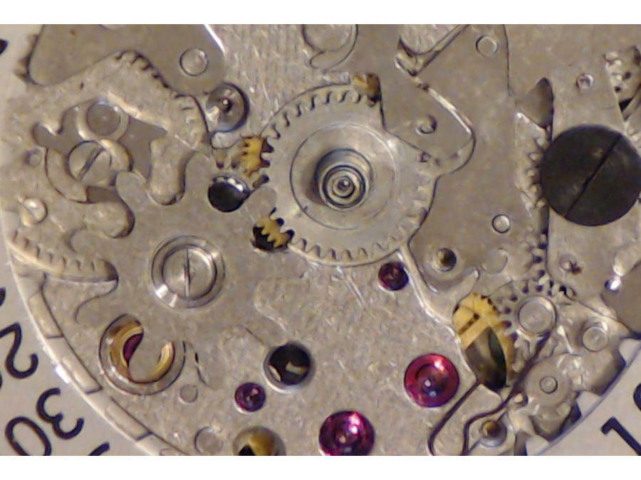
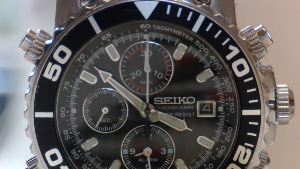
Welcome to my custom made watchmaker and repair video camera. Paul Stuart’s Professional Watchmaker Video Camera Project Historical methods of magnification There are many well established historical methods still used today by watchmakers to magnify watch movements while working on them. Without suitable magnification, it is almost an impossible task. To this day, these historical methods still serve the industry well. Stereo and USB microscopes Modern technology has come to the aid of the watch manufacturing and repair industry. Many watchmakers/repairers use stereo and USB microscopes to assist in their work. These have proven to be of benefit for work on extremely small parts such as pivots, hairsprings and so on. Some of these types of microscopes can be connected to monitors so that one can see, magnified and in real time, exactly what is being worked on. However, sometimes the working distance between the watch and the end of the microscope can make life difficult. Microscopes with a reasonable working distance of say, 30cm to 50cm, or even more can be very expensive. Not that one would require more of course. My watchmaker/repairer video camera project As an amateur watch repairer, I have often wished for a better method to magnify and view watch movements in real time on my computer so that I can, without straining my eyes so much, take movements apart and reassemble them. I’ve already mentioned working distance, I think 30cm to 50cm would be a good with its obvious benefits. Also, being able to capture reference photos and HD video is important. To have that capability to stream live video, and upload to YouTube etc. would be an additional benefit. Well, I had an idea for a lightweight camera that should be able to achieve the above. I think my idea may appeal to others. The project cost was reasonable. More on that later. Could I adapt a webcam to suit my requirements? No doubt the idea of using a webcam has been tried before. However, the zoom capability of most webcams is rather limited and they have wide angle lenses. Nearly all have a fixed lens. But a plus point is the webcam management software some manufacturers provide. To be fair, I have never tried using a decent DSLR or camcorder to achieve the above, but I believe I’m correct in thinking firewire connectivity is a problem between modern cameras and computers to monitor in real time. I think it is something to do with the fact they have SD cards. For me though, they seem a bit bulky and expensive for this purpose. I like tinkering with things, my idea was, what if I removed the fixed lens from a webcam and replaced it with one that could be manually adjusted for zoom and focus, together with an acceptable working distance capability and narrower the field of vision. The following is how I went about testing this idea out. How I modified a webcam After researching several different webcams specifications, I decided t adapt a Logitech c920. The c920 has proven to be one of the best webcams and was recently succeeded by the c922. But it is the c920 I used for this modification. The c920 can do real full HD streaming of 1920×1080p @ 30fps with image size up to 2304x1563p. This is how I went about it: I took a Logitech c920 apart to expose the circuit board, its fixed lens and USB wiring assembly. I removed 2 screws securing the lens assembly, then unsoldered the lens and USB screening wire. The lens, complete with its IR low pass filter, came away from the PCB quite easily to expose the CMOS sensor and its infrared (IR) part of the spectrum. For my purpose the IR part of the spectrum is not needed, so I had to add an IR low pass filter. More about that later. I solder connected 30 gauge (0.5mm) single strand wire between the main circuit board and USB board as follows: TP3 to USB board D+ TP2 to USB board D- TP1 to USB board Vcc Removed green solder mask adjacent to TP25 on the main PCB for the GND connection and GND on the USB board. Used the existing shielding solder tab on the main PCB for a shielding connection to the USB socket housing. Unsoldered the four LED’s from the main PCB at D3, D5, D6 and D8. I could have left the diodes in place and simply put some black tape over them. Both the modified circuit board and new USB socket were then mounted into a custom-made aluminum housing having a CS lens thread. Because the original filter was removed with the lens assembly, it had to be replaced with an IR Low Pass filter and mounted with double sided tape in the new custom housing. I then attached a 5-50mm CS varifocal lens with manual iris and focus. This was a f1.4, 3 mega pixels, 1/2.7” lens and suitable for the original Logitech 1/3” format CMOS sensor. Custom watchmaker camera case, rear view. With Logitech c920 lens removed, custom wiring done and circuit board assembled. Front view without the new lens attached, new IR low pass filter is assembled. Parts required 1 x Logitech c920, these can be obtained at a very reasonable price from auction websites. 1 x Custom made box for the reworked c920 circuit board, and with CS type lens mount. 1 x IR low pass filter (to replace the one removed with the c920 fixed lens). 1 x CS lens – f1.4, 5-50mm, 3 megapixel, manual focus and manual zoom. 1 x 5mm CS lens extension ring. Result I now have a camera to zoom in close and a respectable working distance between 30cm to 50cm or more. It can stream live, record videos and take snapshots. I can see all this on my computer, live as I’m working on watch movements. Example full screen captures at a working distance of 30cm At 50cm Paul Stuart’s Professional Watchmaker Video Camera Project – Parts and Specifications Parts price list Logitech C920 webcam £27.00. I got mine off an auction website cheap because the USB wire was broken. This was not needed anyway because of the new connection I was going to make to a new USB output port in the new case. Custom c920 anodised aluminium (aluminium) case. £56.00 0.5mm copper core silver plated bodge wire. £2.00. From auction website Lens 1/2.7" 5-50mm Manual Iris 3 Megapixel Lens. Features: 1. 3 Mega Pixel, manual focus iris and zoom lens 2. 2.1/2.7" High quality 5-50mm varifocal CCTV IR CS lens 3. Low distortion 4. High resolution £89.00 5mm C to CS lens extension ring. £3.00. From auction website. Total spend: £177.00
 2 points
 -
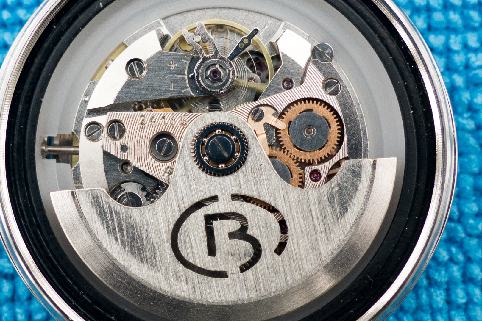
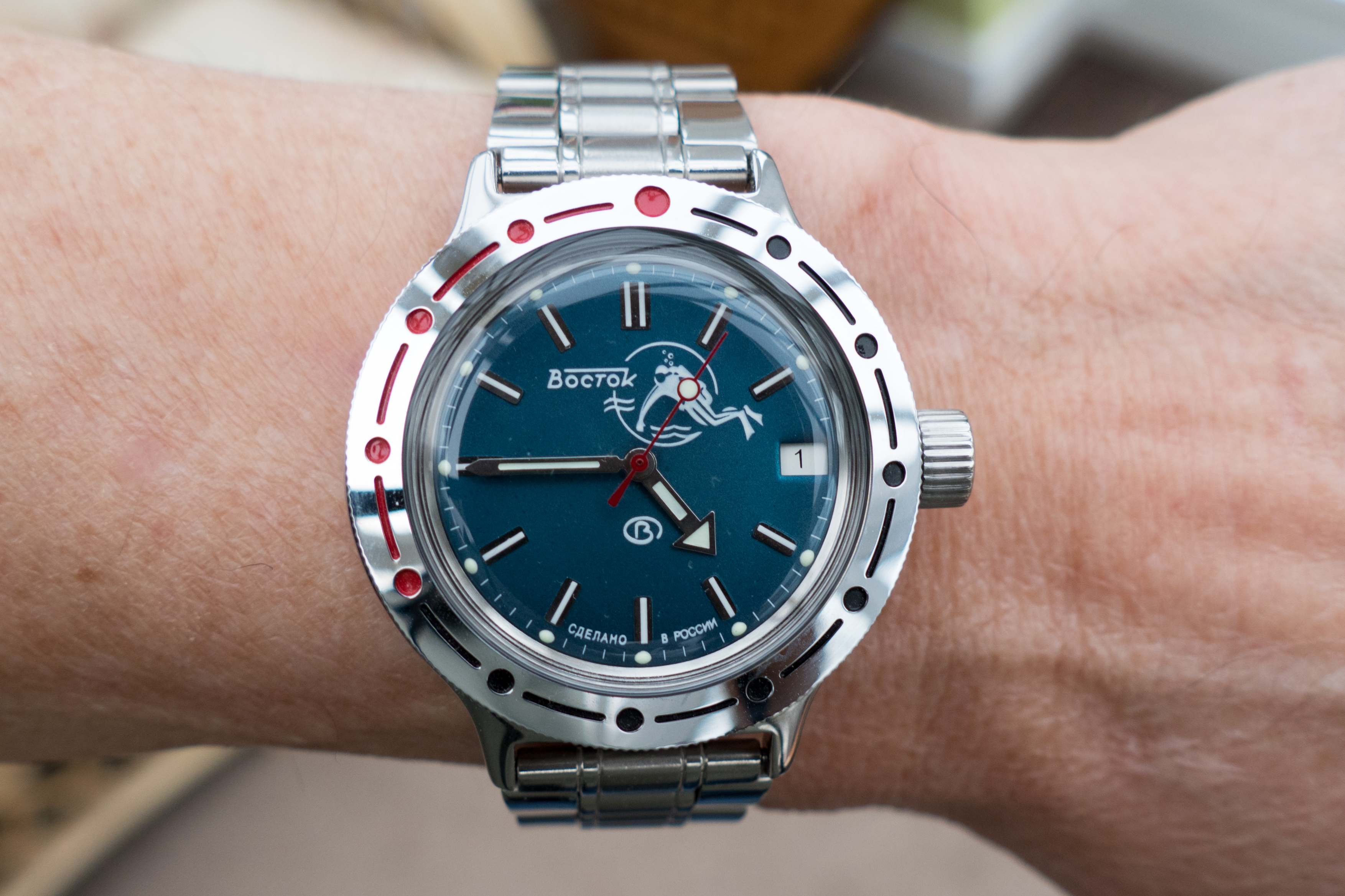
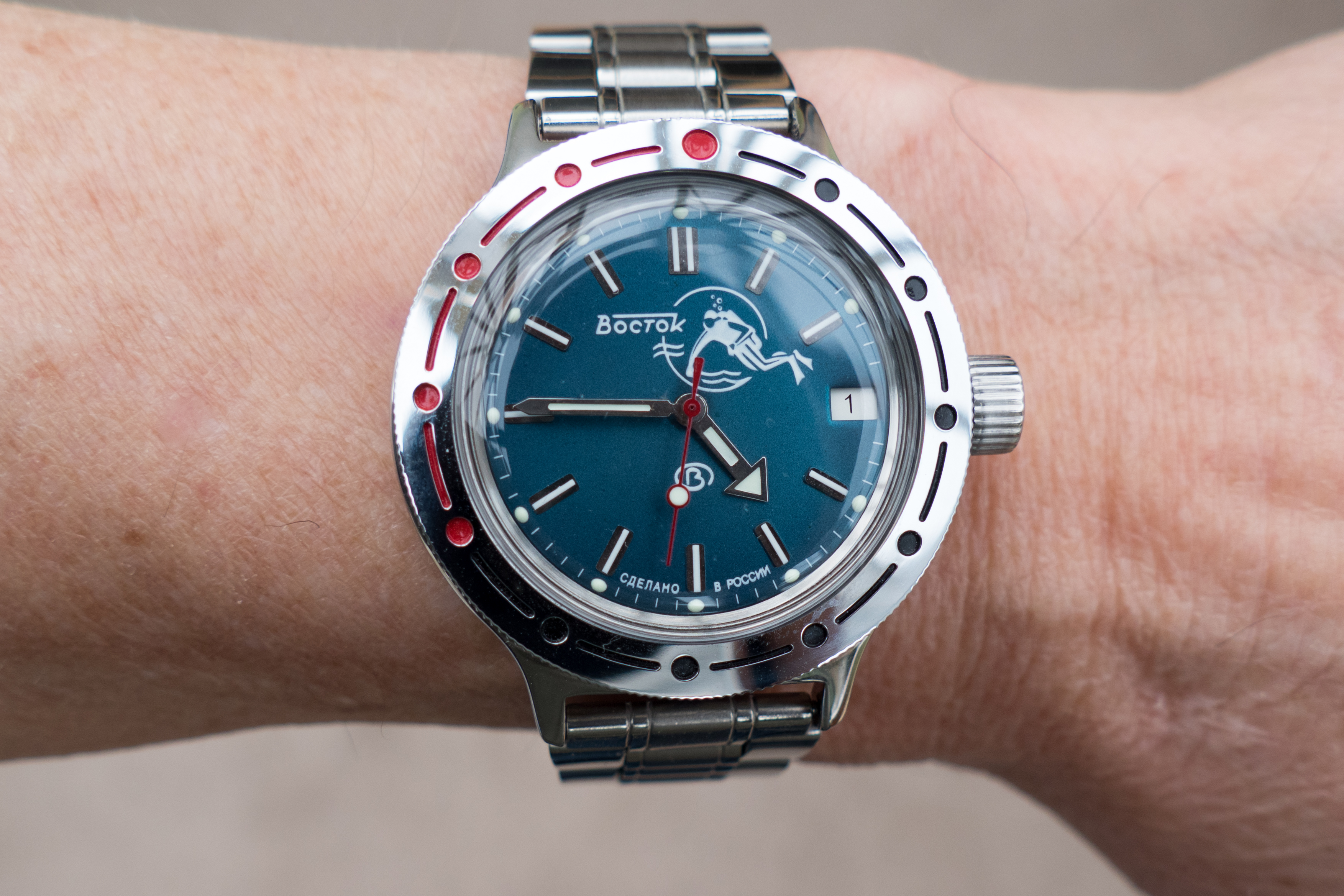
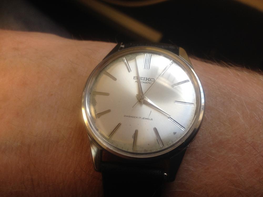
I'm very pleased, having got it back together and it's ticking away nicely. Thanks for your guidance Marc; once I'd put the crown wheel in the right way up it all worked a treat. Just a bit of fiddling with the stem which didn't want to go in all the way at first. Here's the ticking movement: And here's the final outcome, on a cheap ebay bracelet until I find something better: By the way my wife tells me it IS blue, but it still looks green to my weird eyes. Cheers, Kevin


 2 points
 -
Its not often I find good clocks on ebay, this is a real gem. This has been repaired by someone who takes real pride in his or her work. This is the sort of work I miss. I thought I would post this so you can see how well this little silver timepiece has been cleaned and repaired to a very high standard. Lovely finish to the brass work by hand and not by any machine, polishing machines should never be used on clock movements. Nice even bluing on the screws. Cleaned up screw heads and polished with no burs left, the case screws have been cleaned as well. Equal size on the pins and rounded off on the ends so they do not show that horrible cut mark. Regulator tail right in the centre of the platform. It is in a lovely case and a good price. http://www.ebay.co.uk/itm/ANTIQUE-SILVER-CARRIAGE-CLOCK-MANTLE-CLOCK-CLOCK-/391717192081?hash=item5b342a0191:g:vf8AAOSwEzxYOIsk2 points
-
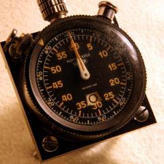
For no reason but the crystal reflection, which I find kind of sexy. Since then I've got a real macro lens but in hindsight maybe it wasn't so necessary...2 points
-
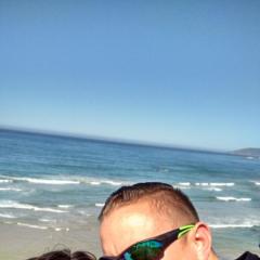
Yup , I live on Oahu . For anyone that's interested , the State fish is the ...Humuhumunukunukuapua'a... a little fish with a big name .
 2 points
 -
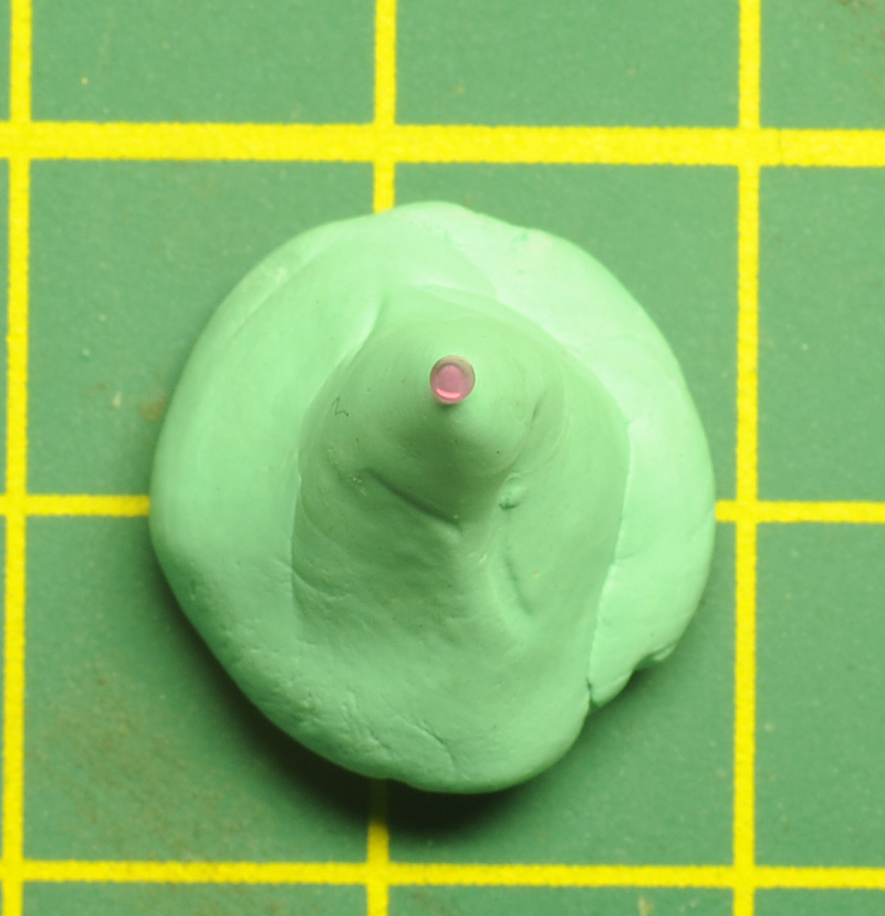
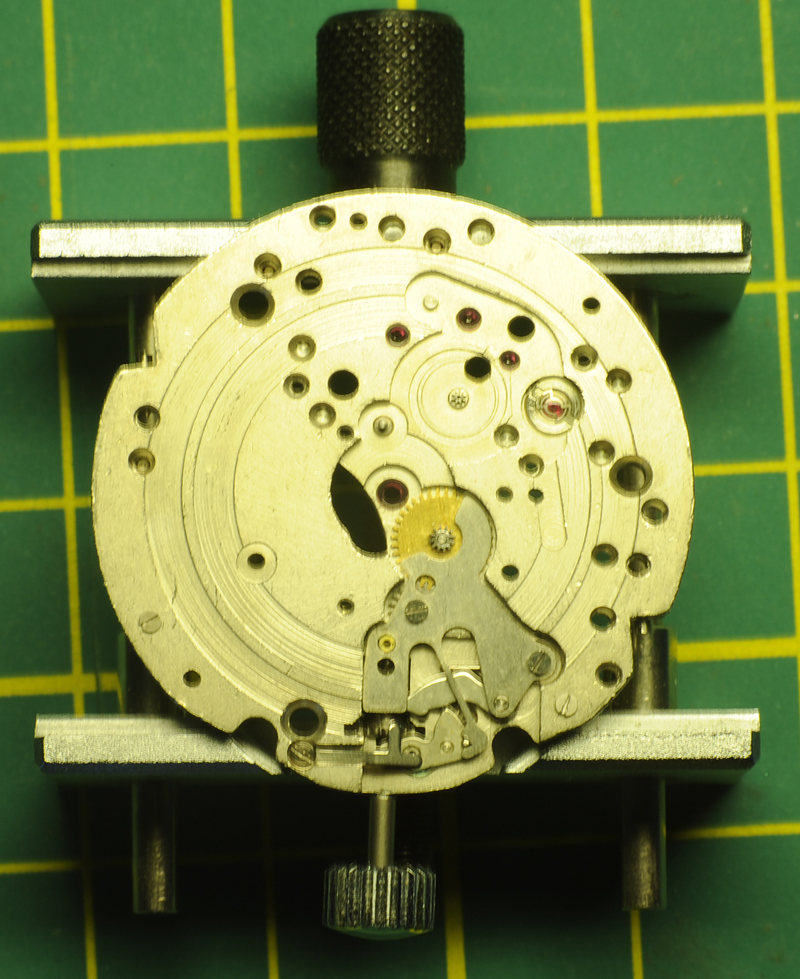
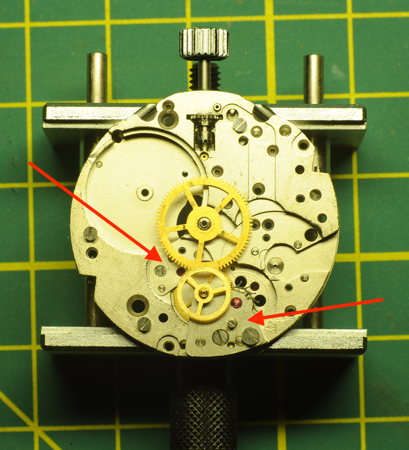
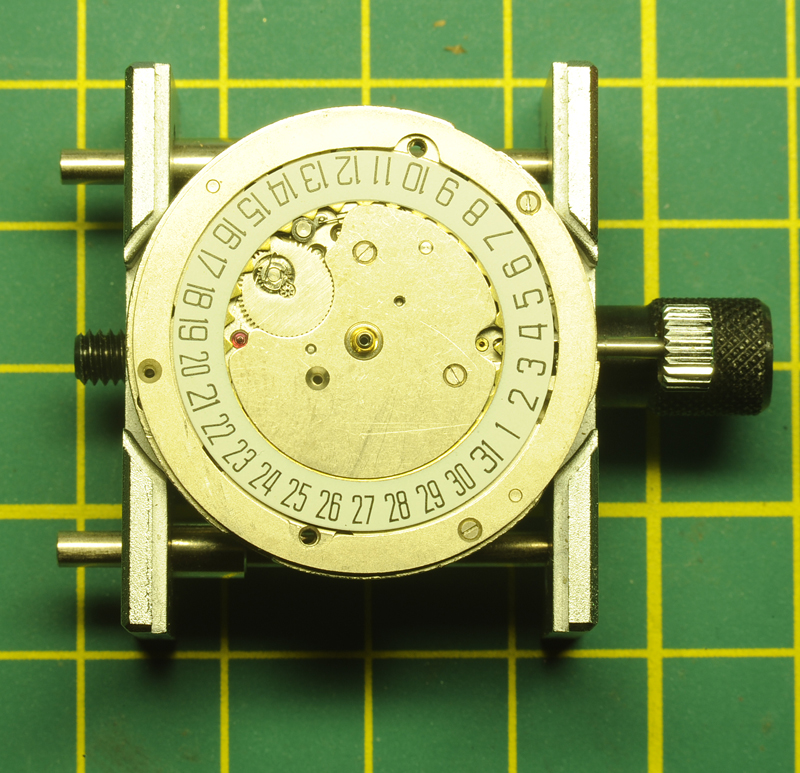
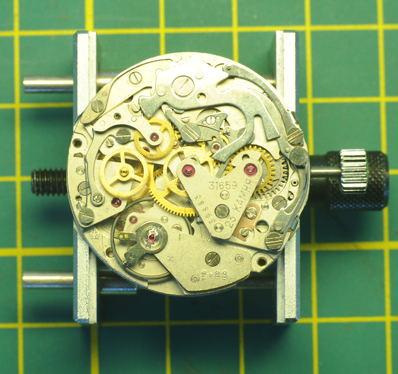
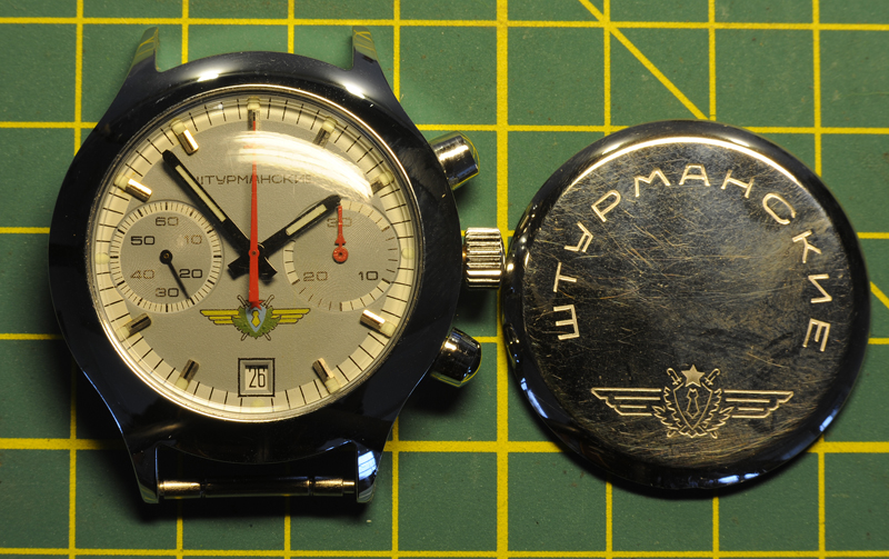
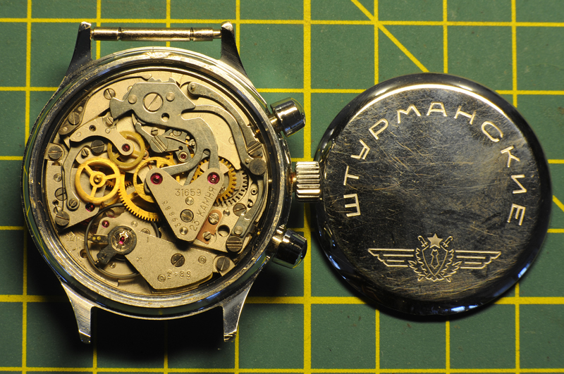
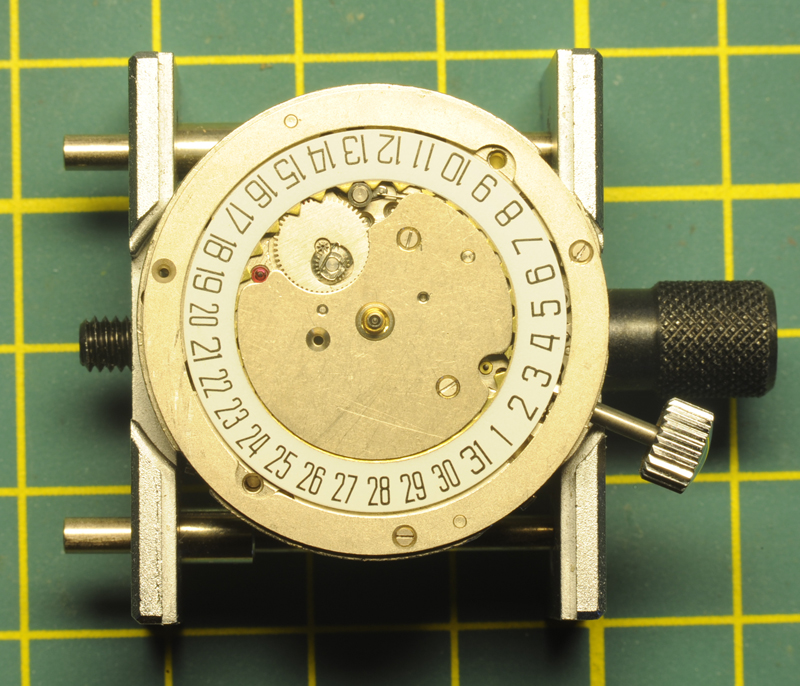
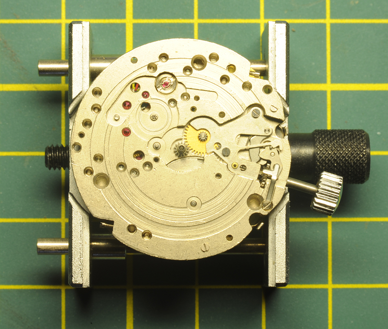
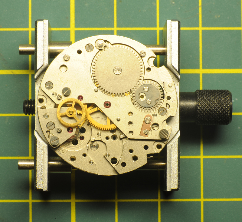
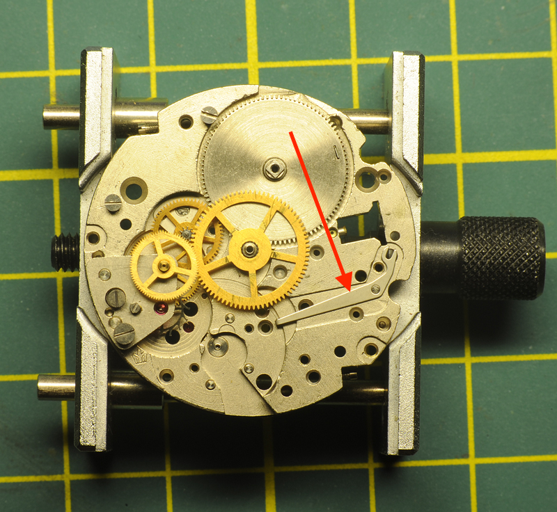
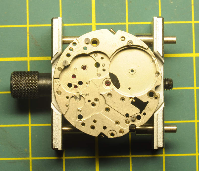
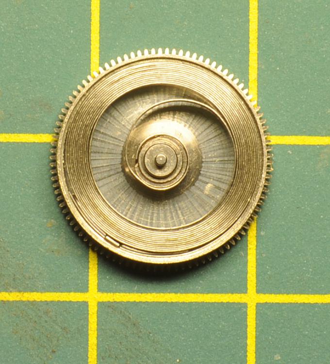
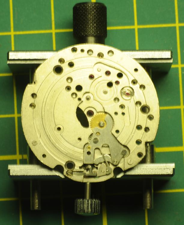
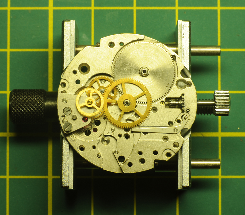
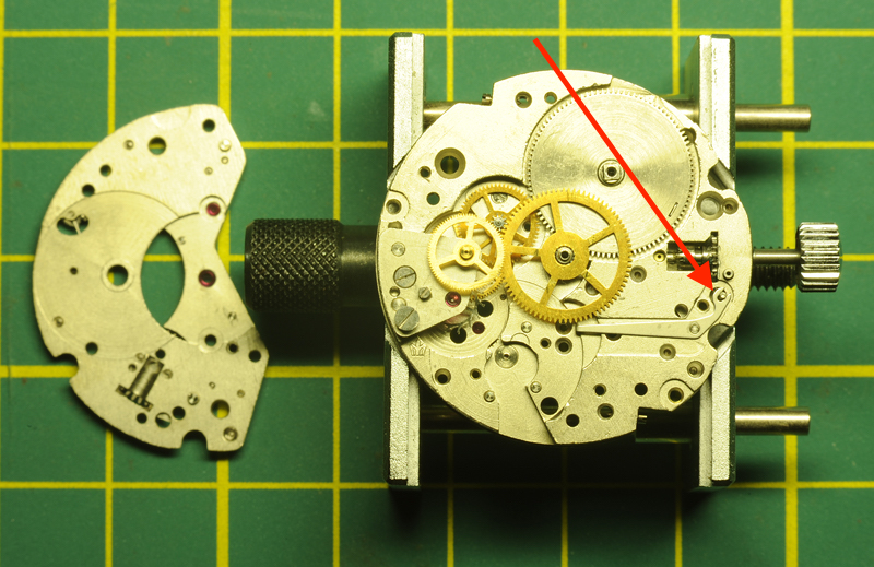
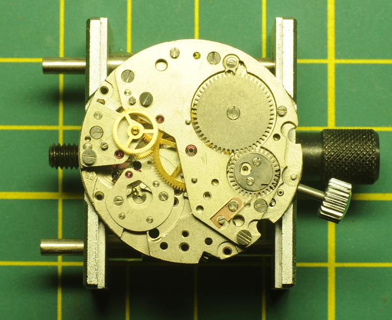
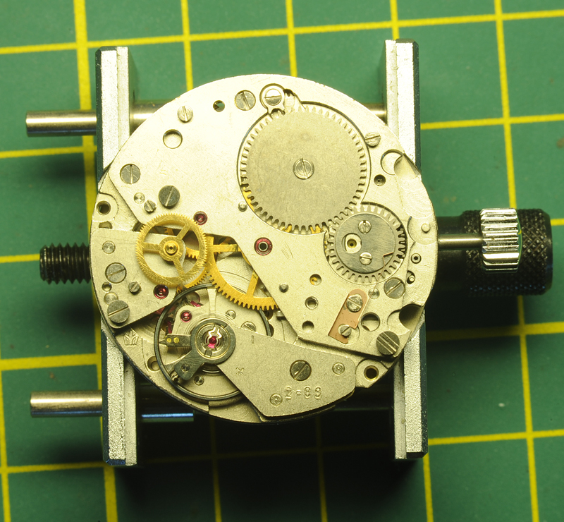
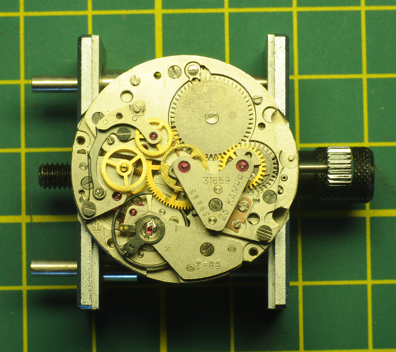
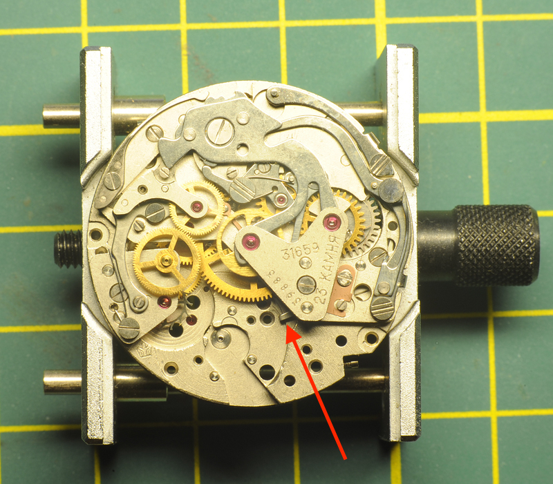
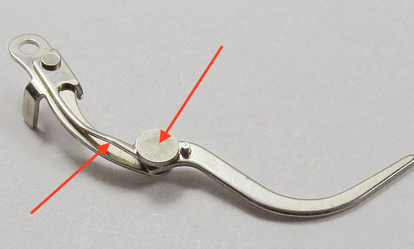
I bought from an ex. Poljot salesman, this undisturbed Shturmanskie "classic" with a Poljot 31659 movement. The Poljot 31659 movement is almost identical to the Poljot 3133 movement, but it has an additional balance-hack. The watch has never been used, never been worn, just sitting in a drawer waiting to see, after all those years, daylight again. Before it gets wrist-time, a service was overdue. The "pop-off" the back-lid was anything but "pop-off". The provided slot was of not much use and I ended up driving carefully a scalpel-knife in between the lid and the housing seam; slowly creating a gap big enough to insert a blunt knife. Even then, it took a huge force to get the lid to "pop-off". Needless to say, the nice, nearly virgin lid has now its first unavoidable marks. The light surface scratches on the lid are very minor, but appear more severe on the picture due to the light reflection. The Plexiglass crystal is scratch free, but has some minor aging-cracks. The inside reveals an undisturbed 31659 movement, with 2-88 stamped in the chronograph bridge. February 1988, that's to date exactly 29 years. I took the movement out, removed the hands and dial. This time the small seconds- and minute recording-hands came off unharmed. However I wasn't that lucky with the big chronograph seconds recording hand. It was so tight, that even with great care, in the end the hand stripped off its pipe-bushing With the hands and dial out of the way, I managed to get the pipe bushing of the pinion without any further damage. As you can see on the picture, The outer ring has one screw missing, so has the calendar center plate ....... I guess the factory worker in 1988 didn't feel like it that day!? Can we still find out ? Stripped the calendar works; Stripped the keyless works, flipped movement over and removed balance assembly and pallet fork. One can just see the hack appearing from underneath the barrel bridge; see arrow; Time to disassemble the chronograph components. Even though for a 31659 one has to deviate from the guide slightly during assembly, I can highly recommend this service guide made by WUS member SLLS on June 2015. Click on the link below to download. Thank you very much SLLS for you excellent and clear servicing guide Service Guide Poljot movement 3133.pdf Remember to re-insert all the screws in their respective holes after removing the component. A bit more work, but it makes life during re-assembling so much easier !! See service guide for part-numbers, additional pictures and guidance. First the Hammer (8220) followed by the hammer-cam-jumper (8356). Before removing the operating lever (8140), I lifted the spring on top of the rivet. This prevents the lever from popping out after the LH-screw is undone, but also makes the installment much easier. Obviously, the spring has to be put back after re-installation. Removal of the operating and fly-back lever-spring (8335), fly-back lever (8180), blocking lever (8200), Blocking lever spring (8335) and sliding gear (8100). Left is the chronograph plate (8281) with all screws inserted in their respective holes. Next the chronograph plate (8281), the Chronograph bridge (8500), the seconds recording wheel (8000), the friction-spring (8290) and the minute recording wheel (8020). According to the guide, the very delicate minute recording jumper (8270) is removed, but I left it in place. If you also leave it, be very aware during subsequent handling of the barrel-bridge !! Next is the coupling clutch spring (8320) and the coupling clutch (8080). This has stripped most of the chronograph components, apart from the chronograph drive wheel (or wheel over 4th wheel if you like); Next is the ratchet wheel (415) and the barrel-bridge (105). Now the hack-lever can be seen. The little spring at the end is very delicate ..... Next is the 3th wheel (210) which has to be carefully manipulated from underneath the center-wheel. This reveals a plate (no number) for the 3th wheel which has to be removed. Instead of pulling the chronograph drive wheel (wheel over 4th wheel), to reduce risk I removed the whole assembly; the train wheel bridge (110), 4th wheel (225) and driving wheel (8060). Be aware of the long pivot on the 4th wheel ! As soon as the train wheel bridge is undone, the escape wheel (705) comes free. Spring barrel, cannon-pinion and center wheel as last. Left is the bare main-plate. The main-spring seemed in a good shape; Time to clean all the parts and lubricate the balance cap-stone in the main-plate. I use Rodeco as a support. Once to small droplet of oil is on the cap-stone, I turn the Rodeco top-down and insert the cap-stone in the chaton. Works very well for me As far as I can see, next to an additional recess in the main-plate, the only difference between the 31659 and the 3133 are these two components. The setting lever has an additional post and the additional hacking-lever. To the left of the hacking-lever the tiny spring which pushes against the balance wheel when engaged. Next up the servicing of the barrel-bridge with click (425) & click-spring (430) and crown-wheel (420). The little screws holding the crown wheel core (423) are known for shearing off, so be careful if you decide to proceed with this step ... Now I had to deviate from the guide. Due to the fact that the hacking lever engages onto the additional setting lever post, I installed the keyless works first; Flipped the main-plate over and installed the center wheel, the complete 4th wheel assembly with escape wheel and 3rd wheel plate (left arrow). Before installing the 3rd wheel, it is now to lubricate the jewel of the 3rd wheel; Install 3rd wheel, barrel and hacking-lever; Make sure the hacking lever is engaged onto the additional setting lever post; Install barrel bridge, make sure 3rd wheel finds its jewel and ensure all the gears are running smoothly before tightening the screws. Lubricated pivot jewels and pallet stones. Install pallet fork & bridge, check correct working and install ratchet wheel. Thereafter I did the calendar works and check functionality. Now a little lesson I've learned: I left the keyless works in the time-setting mode. Later I couldn't get the balance wheel to seat properly ?? So, if you later, during assembling of the balance assembly, wonder why you can't get the balance wheel to seat, better is the retract the hacking lever by setting the keyless works in the winding position. That does help ! After some scratching my head (see above), the balance wheel was back in and the movement came alive Lubricated the balance-bridge cap-stone. No parts reference number mentioned for re-assembling; Replaced the coupling clutch, the coupling clutch spring, minute recording wheel, friction spring, seconds recording wheel and chronograph bridge; Re-installed the chronograph plate, sliding gear, blocking lever spring, blocking lever, fly-back lever, fly-back lever spring, operating lever (remember to put the spring on top of the lever back under the rivet after replacement !), hammer and hammer cam jumper ....... Tested and all chronograph functions are working fine. The initial amplitude is a bit low, around 270 degrees dial down (?), but I'll let it run for a while to see if that improves ..... I managed to get the chronograph seconds-recording-hand back on its pipe-bushing, but time will tell if that holds. Also closing the watch case will require a hand-press ...... not a simple "pop-on" ........ this phenomena has been reported by more people .... Hope that this Poljot 31659 movement walk-through is of any use? ....... else it will be a nice reference for myself That was enough adrenaline again Regards: Roland.


 1 point
 -
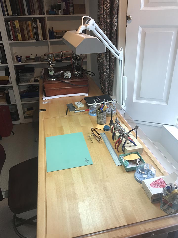
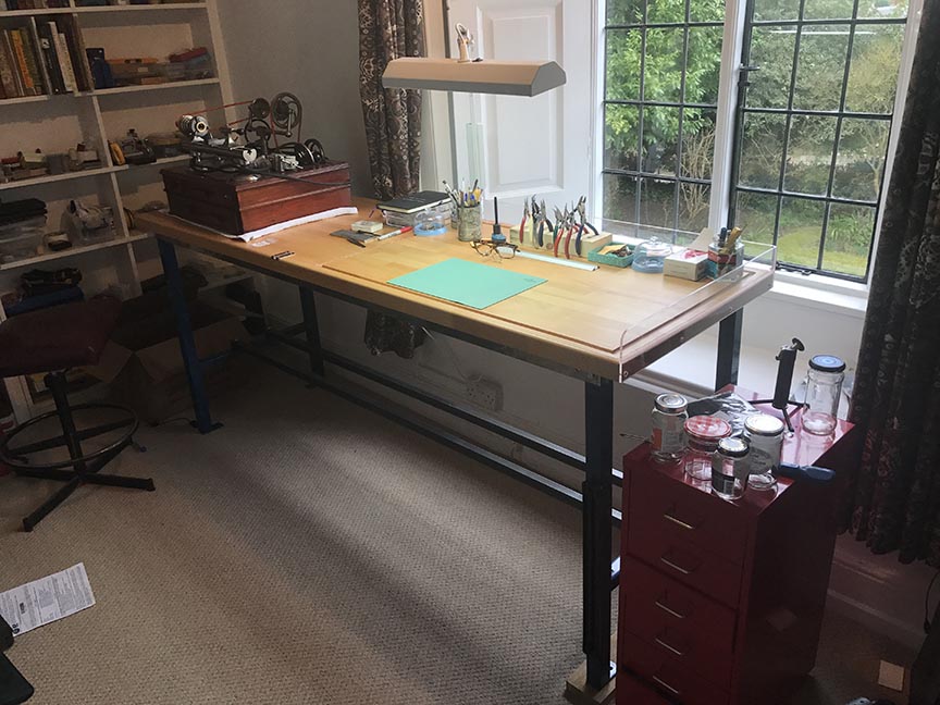
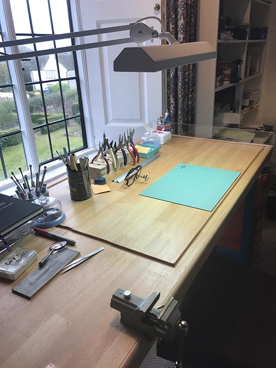
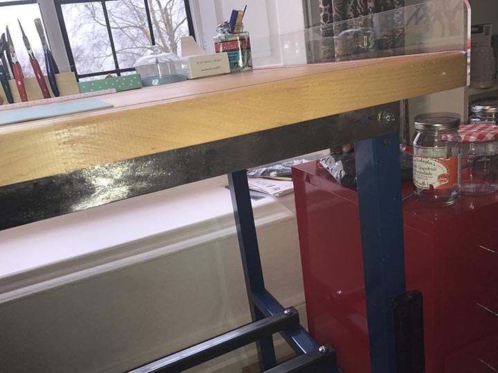
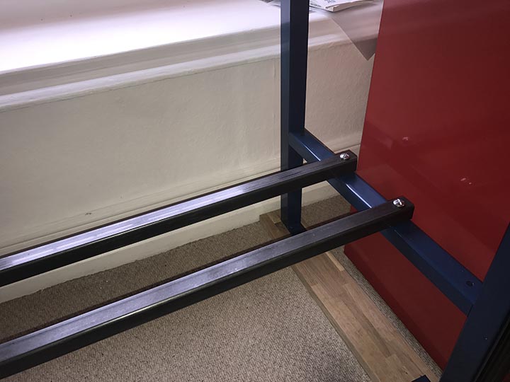
Like a proud father, I feel the urge to show off my latest creation. We recently moved to a new house which finally gave me the space to have an office/workshop. I have been working on a tiny little homemade bench the past few years and have been dreaming of a proper bench. Sadly the ready made ones I wanted are way out of my league. My design goals were: Affordable versatile Free standing (i rent the house and cant drill bolts into the walls) Sturdy I got the original inspiration from Dan Spitz. http://danspitz.com/for-sale/ His concept is to make stunning workbench tops. You then supply the legs. However at £2,000 for the top, there was that budget thing again. I did however steal his idea (I don't actually know if he or someone else came up with it) of the routed groove along the edge. It has already proved to be a godsend in terms of catching small screws, and the odd tool. I decided to add a perspex screen on the back and down one side as I am notoriously rubbish at not flicking click springs etc across the room. So, the basics. Worktop: 40mm solid Beech kitchen work surface from Ebay 2000mm x 620mm - £85 Legs: Steel workbench legs from Machine Mart about £40 including shipping Bench support: 2 L shaped steel struts from an old Victorian bed. £5.00 from a salvage yard, cleaned up with an angle grinder then polished. Struts: 30mm square steel tubing from steel merchant £20.00 Danish oil for bare wood: £5.00 (four coats on either side) £20 for bolts and screws. So I made the whole thing for well under £200. The top is extremely heavy and I haven't totally managed to eradicate minimal side movement and ideally I would bolt it to the wall but as I said I can't. Still it isn't going anywhere and I love it. Of course you don't have to make it 2m long but I wanted somewhere for my lathe. I am building a perspex divider to protect the workbench from cuttings from the lathe. Anyway, I hope it might give some of you some ideas.

 1 point
 -
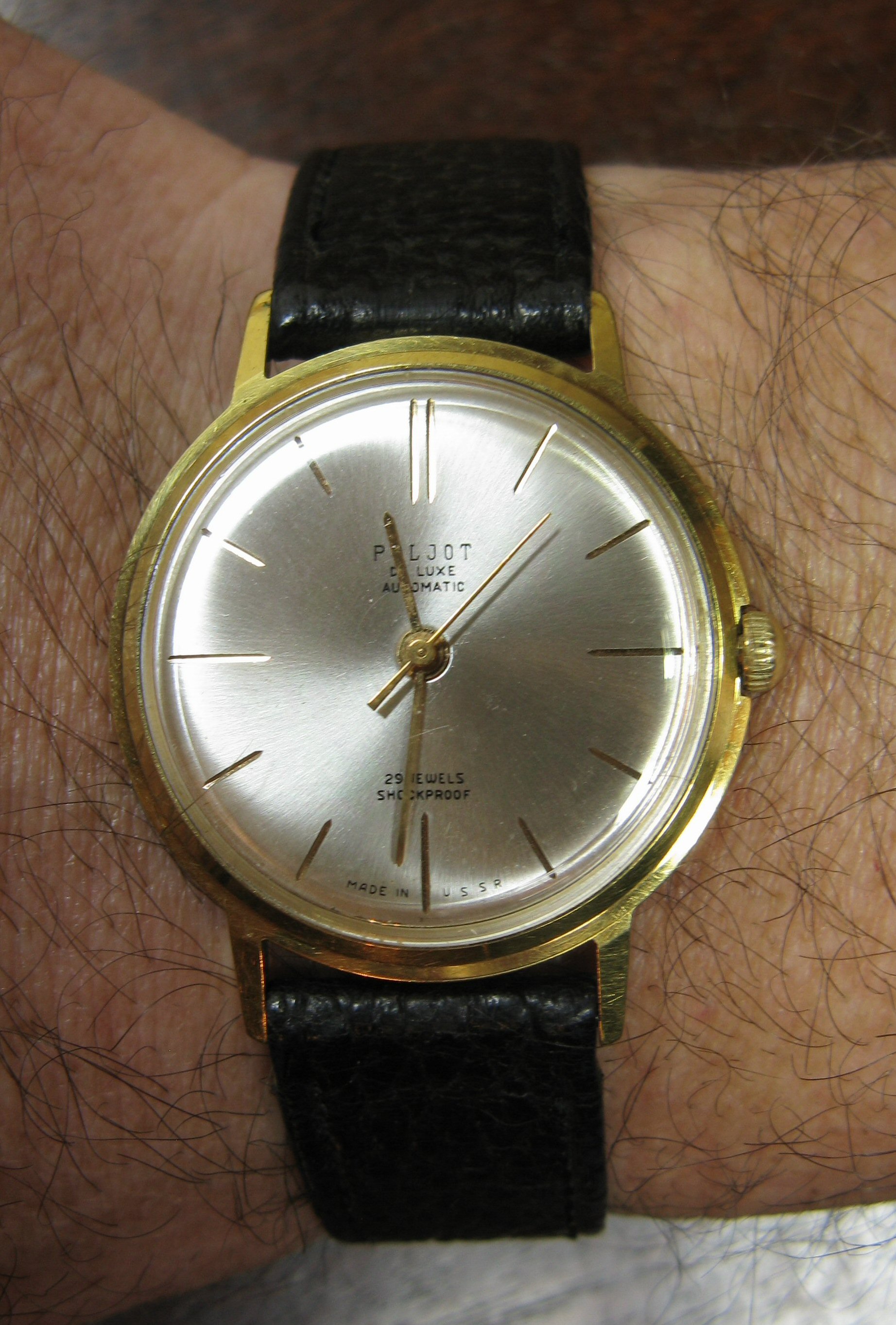
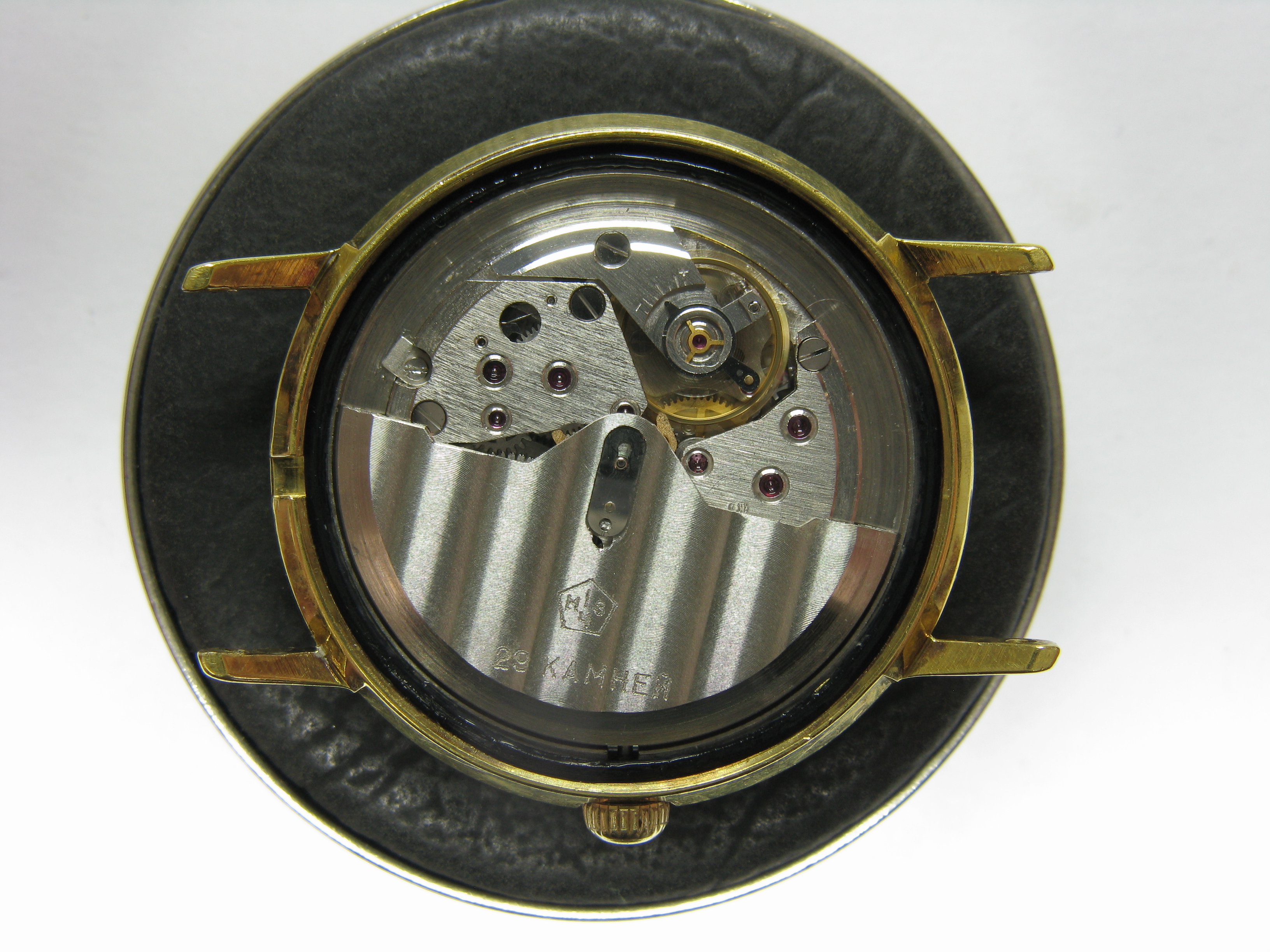
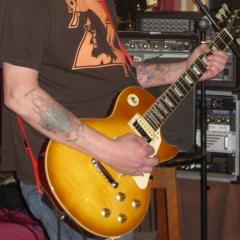
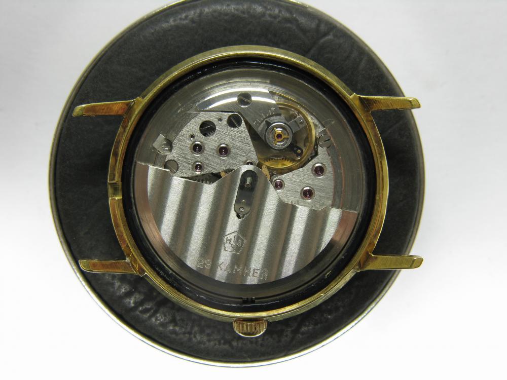
A bit of vintage Russian for me this evening.... Poljot De Luxe 29 jewel auto. Featuring the lovely Poljot 2415 "Orbita" movement, the thinnest auto movement of its day apart from the micro rotors. I just finished a full strip down service on this today and am giving it a little test drive. I will probably post the full walk through shortly.

 1 point
 -
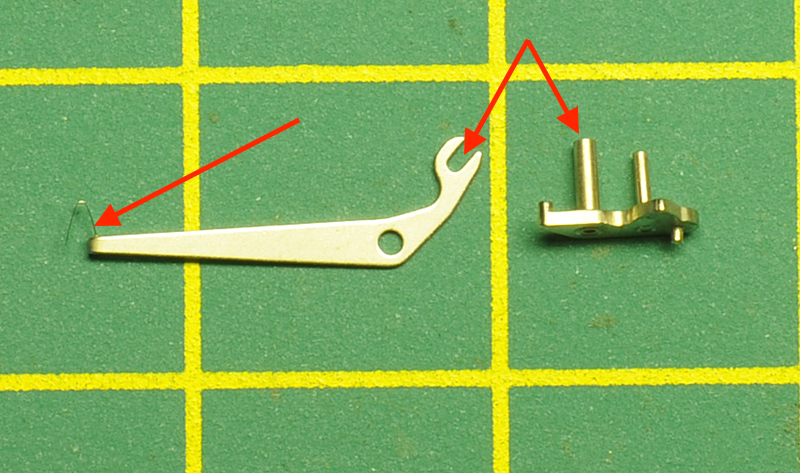
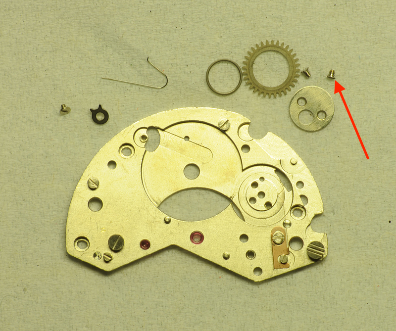
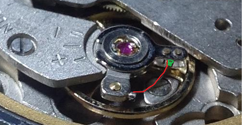
If you're going further back than the 7s26 watch out for the calendar jumper spring. If you disturb the calender wheel, it will ping off into the universe Also the day change has a little wire spring underneath the lever This is what it looks like Sent from my SM-G920F using Tapatalk1 point
-
It's dark turquoise... In fact, it's a blue dark turquoise ...no green .. However, it's a beautiful watch you have1 point
-
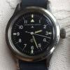
Its been a Sportsmatic 15035 cal 6601A for me this week so far. It suffers a little dial flaking but its still nice and I suppose its not doing bad for something made in October of 1963 and just feels very comfy on the wrist.
 1 point
 -
Quick update: I received the adapters and was able to connect the Witschi mic into the preamp just like I have been using it with the other mic with just ok results. The amp is transmitting ok, I can see the big jump in the waveform when I tap on it. But just like @tobmack said, the signal is too weak and when I increase the preamp it boost the noise as well. Quickly compared with the clip on Korg mic and it had a discernible waveform. This was all quick and dirty because of time restraints, I'll post pics asap. Thanks for your input! Sent from my iPhone using Tapatalk1 point
-
Today I'm wearing my 37mm Seiko 5. Give my poor old wrist a rest from my bigger watches Sent from my SM-G920F using Tapatalk1 point
-
I think most PC mic inputs will be able to provide power (albeit at a low voltage) to allow headsets with electret microphones to work. Adds another layer of complexity when trying to figure out how the mics are wired on timegraphers though. I think checking the watch-o-scope thread is a good suggestion as above.1 point
-
That is awesome. I love clocks and the different stories the tell. I will keep looking for a long case to work on. I love the amount of knowledge you have with clocks. I love the eBay questions. Keep up the good work. When I posted on this thread none of the other comments showed up, till I posted. I was a little too late. Ha ha.1 point
-
The output from the vibration sensor on the stand is too low for the PC to use without preamplification. If you were to increase the sensitivity of the microphone input on the PC to compensate for the low signal, it would also boost the noise. The signal would not be usable. I would suggest reading the thread on this forum about the Watch-o-scope project. There is an amplifier design published by Stefan which others have built for the purpose of boosting the signal from a Witschi mike for use on a PC. There is a suggestion by one of the contributors for an off the shelf amp that also works. I built Stefan's amp and attached my Vibrograf B200 watch stand to it; it works marvelously well.1 point
-
Would it really not have a preamp in the stand? Even my cheap Chinese timegrapher uses a preamp. You could still hook it up to a PC (I plan to try WOS as well), but you'd need some minimal external electronics to provide power to the pramp.1 point
-
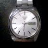
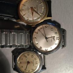
If you need to look up watch names the following site is very useful : http://mikrolisk.de/show.php Tempo as a watch name was first registered in 1904 and a lot of pocket watches turn up with the name on the dial as is the case with many of these names the companies who make them are bought up and change ownership and the name is then registered to the new company your watch is typical in style to watches produced in the late 60's to mid 70's. Using the site above will allow you to work out who owned the company in that period, the name is still in use today.1 point
-
Looks like it could be @szbalogh video? He is the master of replacing jewels and repairing pivots? If i would do it i would replace the jewel? If that is possible? think it would be difficult to enlarge the hole? As you probably need to set the plate up in a lathe or some kind of device to get the hole perfectly straight?1 point
-
Some more information on the project. Obviously the webcam requires the latest software and this can be downloaded from the Logitech website. I use a Windows 10 laptop. Windows 10 come with a built in camera APP that when opened will show a full screen image of what the camera is viewing. The APP can be used for making a video with voice over using cameras built in stereo microphone, or, for just viewing live the item being worked on. I have experimented with OBS (Open Broadcasting Software). This allows for more control over the Logitech webcam settings when pulled up for editing in OBS. OBS can also be used for making the recordings or simply viewing a watch movement while working on it. I must point out the importance of good lighting during filming.1 point
-
I think these hands were for a specific, I.E. Roskopf, pocket watch, but I'm not sure why the card would say both 13 & 10 1/2 lignes. I did see an auction for hands where the card was marked " railway hands for 13''' Roskopf watches"1 point
-
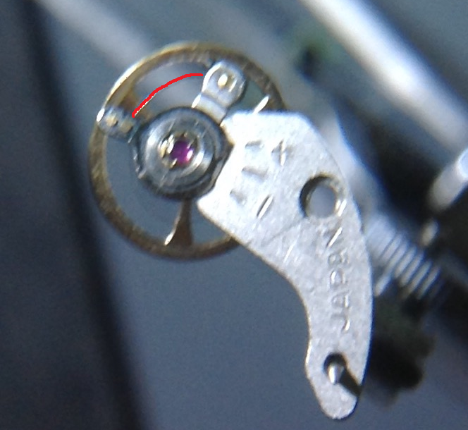
That end curve seems total wrong to me. It should be concentric around the balance staff. Is it like this if put back in the movement? It seems to me that the HS end curve is pushing hardly on the outer regulating pin (green): If so, then the HS cant be flat and centered and sticking to something. This can lead to low amplitude and noises that the timegrapher recognizes false and showing totally wrong rate even if the BPH is selected correctly. Great beat error does not lead to such high difference in rate.
 1 point
 -
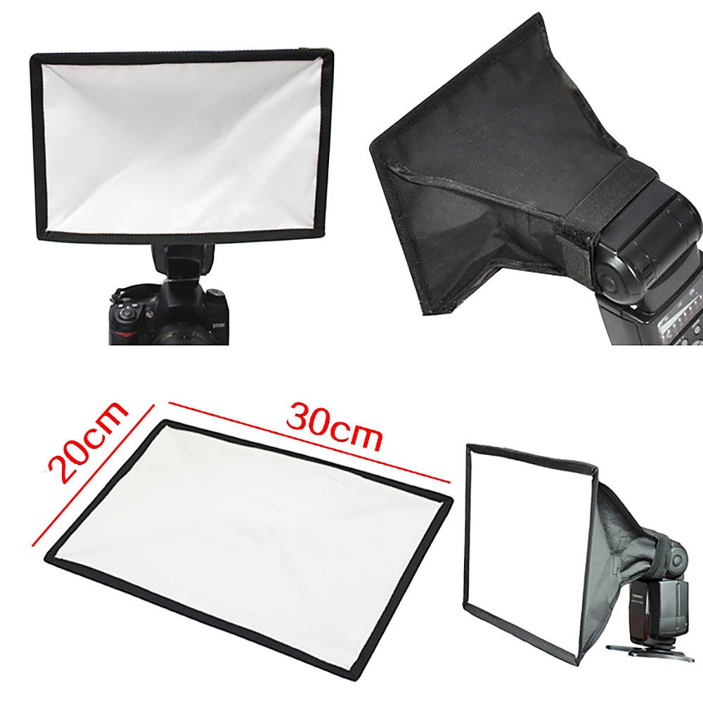
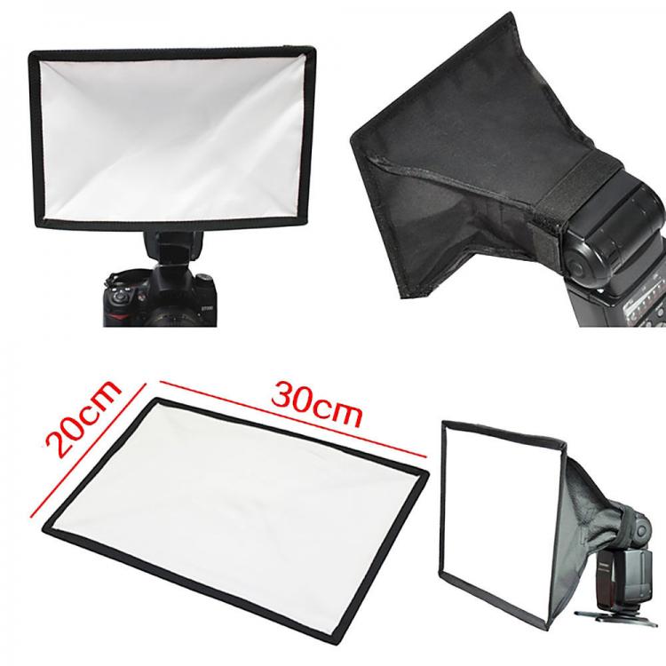
for a diffusor you can use tracing paper, works perfect. Or a small softbox which normally is used for a flash. Remember every diffuser will effect in loosing some of the light. Something like this:
 1 point
 -
I think you will find the LED's are "cool white" and that's the reason for the blue/violet output. High lux warm or white LED's would be better and, as suggested, a diffuser would help and it needs to be opaque white and not clear crystal type diffuser. Take a look at the test output photos of the watchmaker camera I've made, the movement photo is taken in my dining room that has warm white LED's and without any extra LED lighting. If I were to use an LED lamp to aid the camera directly, I would opt for daylight LED's, something around 4500 lumens. Custom made watchmakers' camera1 point
-
Perhaps 10 1/2 lignes? Old unit of measure still used in watchmaking. I think it is sometimes represented by ''' .1 point
-
Yes, beautiful water at that. Hey Louis, didn't know you frequented these parts!1 point
-
After you have mastered what you intend to do with the P/W. You should try a Gents watch, not to complected, get used to handling the small parts, take everything to bits and I mean everything. Next up one with calendar work, auto and ladies small movements then ladies calendar work, auto. If you were on BHI course you wouldn't be working on chronographs until your final years, that would be after you master how to make and fit a balance staff.1 point
-
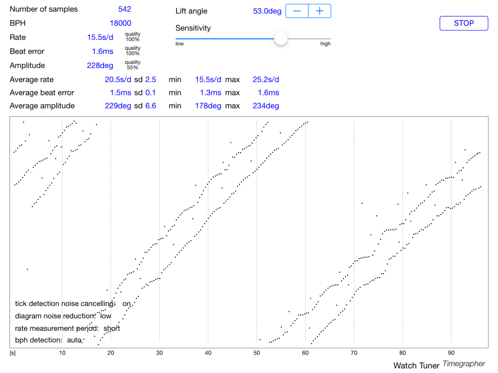
I appreciate it. I attempted to throw it on my "Timegrapher" aka the Watch Tuner Timegrapher app on my ipad with a mic to see how it was doing. I honestly have no idea how accurate the app is, I am guessing it is not terribly accurate just using a stock headphone mic catching all the surrounding noise but this is what I got from it. Not the prettiest but my setup isn't exactly the most accurate setup either.
 1 point
 -
Well I would definitely start with Moebius 9010 (for train wheels and balance endstones) and 9020 (for train wheels) if you are working on Pocket Watches. Moebius 9415 is a must for Pallet/Escape wheel teeth. A quality silicon grease. Moebius D5 is essential (barrel arbor, motion work). Molycote DX or Moebius 9501 grease for keyless work. Moebius 9501 or 9504 for high friction (e.g. Cannon pinion, Setting lever spring and anything at high friction). Moebius 8200 grease for mainspring. Moebius 8217 for barrel wall (automatic watches) It's a lot but at a minimum get 9010, 9415, D5 and 8200 I hope this helps. Recommended Lubricants for Getting Started.pdf Moebius_Oil_Chart.pdf1 point