Jump to content

Recommended Posts

Posted (edited)

image.png.e25961afb8df7d27c9d228f960ca476f.png

image.thumb.png.c1e5de6a24e89c5d7e307e45dca3de78.png

image.thumb.png.8a1b9a2a8076a39210efac4e7bc7d40a.png

image.png.9da7261626780a97c34d438661f200fb.png

image.png.570aeb4bf77de5ba2864b12ad968c640.png

Some time ago I bought a Bergeon micrometre (and a Seitz jewelling tool) to be able to replace damaged jewels. The micrometre works perfectly down to the exact hundredth of a millimetre but trying to measure my first jewel I bumped into a very unexpected problem; the height adjustable round table fouls the spindle (circled in red).

I don’t think, or rather I hope, that the micrometre isn’t out of order and can be adjusted so that the spindle does not bump into the table. But searching high and low I just can’t find any documentation or user manual for this type of micrometre. Being a hobbyist having spent a small fortune on these tools, this situation is very frustrating.

So, the question is, what can I do to adjust my micrometre? As I have no clue what the various parts of the micrometre are named, I have given the various parts in the pictures a letter (in yellow) so that if anyone who knows how do this (and takes pity on me :unsure:) more easily can guide me.

Keeping my fingers crossed. Hard!

image.png

Edited by VWatchie
Tried to remove the last picture at the bottom of the post
Posted

Hi Watchie   from what I can see  and not ever having used one of these, the table is for supporting parts being measured and in no other way interferes with the actual measurement. So by fitting a shim or disc with a lesser diameter to the table top to allow the arm to clear the table and support the piece being measured  may solve the problem . 

Posted (edited)

it looks to me that if you loosen the two screws A & B then move the micrometer away from the table, move shaft C, which is now loose to the middle of the table E.

Tighten the two screws A & B 

You should the have the meeting point of the two shafts in the middle of the table and both point will be able to meet each other.

Edited by Alaskamick
modify
  • Like 4
Posted (edited)
16 minutes ago, watchweasol said:

Hi Watchie   from what I can see  and not ever having used one of these, the table is for supporting parts being measured and in no other way interferes with the actual measurement. So by fitting a shim or disc with a lesser diameter to the table top to allow the arm to clear the table and support the piece being measured  may solve the problem . 

Thanks for the suggestion and the thought had occurred to me (lo and behold ;)) but I really don't think that's how it was designed and meant to be used. @Mark uses a similar micrometer, and here you can see how the table is supposed to support the jewel while being measured. I really don't want to add an extra disc/shim as it will introduce another piece to handle, and I'm not even sure how well it would work. Well, as a last resort I guess it could be OK.

Edited by VWatchie
Posted
11 minutes ago, Alaskamick said:

it looks to me that if you loosen the two screws A & B then move the micrometer away from the table, move shaft C to the middle of the table E. you   should the have the meeting point of the two shafts in the middle of the table and both point will be able to meet each other.

Yes, I've considered that as an option too, but then the scale wouldn't be correct. I guess if I move it a millimeter I could always subtract a millimeter from the reading, but sooner or later I'm going to forget and mess it up. Anyway, thanks for the suggestion and I might try it if a better (or more correct) way doesn't come up.

Posted (edited)

You shouldn't have any trouble. Once you have the two spindle flats touching in the centre of the table all you have to do is adjust the location of the micrometer scale, as with any micrometer they can be altered easily. It is normal practice.


I didn't notice that the ends of the two spindles were Flat.

Just bring them together after loosening the two screws earlier mentioned, then you adjust the scale by loosening collar H, line the micrometer up where you can see it easily then retighten H.

Screw L may lock the micrometer to stop it turning so that will need ti be loosened a little


Get the LH side in the right place first with the flat in line with the centre of the table then move to the micrometer side and start altering that.

Edited by Alaskamick
Posted

if i am correct you should be able to adjust the left pin or what to call it . By unscrewing  the A and B screws . never mind the right pin isn't zero . That you can adjust later.  The big screw on the ratchet is only for  taking the click mechanism  apart inside the handle .  To adjust the zero on the scale loosen the big hex nut on the  back of the scale . And turn the scale to zero .  That way you will get clearance  for the table. 

  • Like 1
  • Thanks 1
Posted (edited)
41 minutes ago, Alaskamick said:

it looks to me that if you loosen the two screws A & B then move the micrometer away from the table, move shaft C, which is now loose to the middle of the table E.

Tighten the two screws A & B 

You should the have the meeting point of the two shafts in the middle of the table and both point will be able to meet each other.

I believe after he moves C, he'll have to adjust H,L and K to re-establish his zero point, which is C and F touching face to face. EDIT: @rogart63 has it correct!

Edited by FLwatchguy73
corrected info
  • Like 1
Posted
2 minutes ago, FLwatchguy73 said:

I believe after he moves C, he'll have to adjust H,L and K to re-establish his zero point, which is C and F touching face to face. EDIT: @rogart63 has it correct!

Maybe not 100% . The K can be used to align the zero to the scale to zero .  It no harm in trying . As long as you  arne't loosening tha screws to much.  Look at a  normal micrometer . They work the same way . 

  • Thanks 1
Posted

You can definitely move the fixed anvil toward the mic head (to the right). Just enough that you clear the table. On one of mine there is only  maybe 0.10mm clearance, but that's fine. Once you've done that show us what it's doing on the scale and we can advise.


The collar H is to tighten a collet that takes up the play on the spindle. You won't need to touch that.


  • Thanks 1
Posted

Maybe this vid helps. It looks like its possible to have the the table in the centre when on zero by moving either end and then just  zeroing the micro afterwards.


Posted

image.thumb.png.9490c5b72ff2d70760b53c35141321de.png

image.thumb.png.7b08bfcf78e130e5789865e90193be84.png

image.png.eda5ca316c2eaf82313ff1cec55c9cbe.png

Thanks guys! :thumbsu: All your support really makes me warm at heart! :wub:

As you can see, there has been some progress. (being someone who barely held a screwdriver in hands before the age of 55 I feel pretty proud of myself). Anyway, can't get the scale right. I loosened the big hex nut (even removed it as you can see) but the nut seems to be fixed to the screw, and no matter how I fiddle with it nothing happens. I guess something else has to be done to get it right...

Keeping my fingers crossed you can help me again!

Posted

Put the screw/nut back on, you don't need to move the thimble (the barrel with the graduations 0-99). For future reference, it's held in place with that screw/nut, but is fitted on a taper and needs some coaxing to get off and move around.


If you loosen screw K you can move the inner sleeve, it will just slide around. Get it where you want it and tighten K and you're done.

  • Thanks 1
Posted (edited)

The nut you have undone is only part of the micrometer mechanism, nothing to do with the mounting of the unit.

As I said in my earlier post try loosening screw L which I think locks it in place. also try undoing the  Ring H.

Something frees it up and allows it to move back and forth

Edited by Alaskamick
Posted

image.thumb.png.a3d82b348f2a2569683e21a6c070c616.png
Mission accomplished. The Eagle has landed!

image.png.b9dd3e3da90e2ecf1b0cd9e7e62bec0b.png

So, I’m all good to go! Just can’t thank you enough guys! I know that for you seasoned repairers this is nothing special, but me, well, I feel like I’ve successfully taken off in a rocket! :lol:

For those of you finding this thread in the future here’s some additional info that I learned on the way.

After having removed screw A and B the spindle C just wouldn’t move pulling it by hand. So, I tapped on it ever so lightly horizontally in the direction towards spindle F and it moved in increments. To tap I used the plastic part of the hammer in the picture.

I also needed to rotate the spindles C and F slightly. I did this by grabbing on to the thick part of the left spindle C (after having tapped it out a bit) with pliers with a bit of transparent and though plastic film (zip bag) in between the pliers and the spindle. To rotate the right spindle F I simply used a small BAHCO adjustable wrench.

Loosening screw K as @nickelsilver and  @rogart63 point out is indeed the way to get the scale back to normal! The inner sleeve can then slide as well as rotate without affecting the thimble (the barrel with the graduations 0-99).

I’m really thrilled to own this beautiful precision tool! It gives me the same feeling that I get from looking at a really fine watch movement.

So again, a really big thank you to all of you! :thumbsu:
 

  • Like 5

Join the conversation

You can post now and register later. If you have an account, sign in now to post with your account.
Note: Your post will require moderator approval before it will be visible.

Guest
Reply to this topic...

×   Pasted as rich text.   Restore formatting

  Only 75 emoji are allowed.

×   Your link has been automatically embedded.   Display as a link instead

×   Your previous content has been restored.   Clear editor

×   You cannot paste images directly. Upload or insert images from URL.

  • Similar Content

  • Recently Browsing

    • No registered users viewing this page.
  • Topics

  • Posts

    • Thanks for this post MikePilk, I just came across a similar problem with an Omega 1022.  The problem I had was the seconds pinion spring was bent out of shape and did not even engage with the wheel properly, so the seconds hand was not moving at all. (no power loss though :) I removed the automatic module so I could access the spring and work on it. Once I bent it back close to the right shape, I experienced the same problem you reported about power loss.  Many tweaks later, and the seconds hand is moving properly again, with amplitude back to good numbers again. Cheers
    • After cleaning up the pivots, I made bushes on the lathe. At this point I've pressed in 6 bushes (3 sets) and the wheels turn smooth. What I can also tell you, is that I'm not looking forward to final assembly. Getting the pivots aligned seems to get exponentially more difficult with each wheel that is added.
    • Islands are interesting places to live depending upon their size and other factors. This is a bigger island and it has a bridge to get there at least on one end. It's also big enough that you don't have to go someplace else to get things typically. It can be a problem if you get a job in Seattle though. Yes I've known of people who commuted from the island to Seattle for a job and I don't quite remember how many hours it took but it took a long time. So basically islands are nice if you don't have to leave very often.
    • Thanks @JohnR725! Everything you say makes a lot of sense and is encouraging to read.
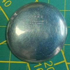
    • isn't it nice to have a decent case open or when the case doesn't want to be opened? In the case of a Rolex watch that supposed to pass specific water resistant testing you probably do need to tighten the back down. But they shouldn't be tightened so much that they risk stripping the threads out. Then the other problem that comes up is the gaskets can start to disintegrate and then getting the back off can be quite a challenge unless you have a really good tool and perhaps some penetrating oil to loosen things up. Yes really nice case marking. When I was in school we were taught to mark the cases and  the American watch and clockmakers Institute even had a? So if you joined at one time they would give you an identification number. They were explaining or giving an example of if the watches ever found in you have a unique number they can perhaps figure out the history of the watch or identify the body it's attached to for instance not that that probably comes up that often. So you got a unique number and even made a special metal stamp that you can purchase. It wasn't a super big aggressive stamp but still it left a mark in the back of the case. Then I heard from people at work on Rolex watches they were using a felt pen indelible but later on they decided that was bad because apparently the ink could release  chemicals although it seems like once it's dry that shouldn't be an issue. Then of course today was nice is you can keep computer records sealed have to mark anything at all I personally find it's best to leave no reference behind that you were even there. Especially when you have a beautiful watch that has no markings at all and now it has your scribbling all over it not good typically if there is a typical and watch repair?  a lot of minor repairs you don't need to do a complete servicing. But beyond a certain point you're going to have to take apart a lot of stuff you're going to disrupt the lubrication even if it looks perfect right now and yes you might as well just go ahead the service the whole thing. also in a watch like this where a lot of things seem to be going on the complete service would be better then you'll know exactly where you stand versus dealing with unknown mysteries for prior repair.
×
×
  • Create New...