Leaderboard


Popular Content
Showing content with the highest reputation on 07/31/18 in all areas
-
I'd really like to know as well. Not living in an English speaking country I often find it near impossible to translate the English names for various petroleum products into something meaningful in my own language. Google translate isn't much help in this context translating verbatim. And, to make matters worse, most horological suppliers (like CousinsUK) aren't allowed to ship anything flammable to Sweden. How do you get hold of this stuff if you don't live in a large country like USA, England, Germany, France, and so on? There just aren't any local suppliers, at least none that I've been able to find.2 points
-
Lighter fuel is made to burn easy and smell good, not to clean parts. As a direct replacement I recommend petroleum ether which is highly refined. I think I wrote this five times this week only.2 points
-
Clean them with a brushing pad (on a rotary tool if there is stubborn dirt), then white petrol plus few drops of machine oil.2 points
-
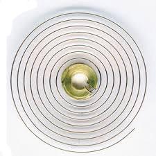
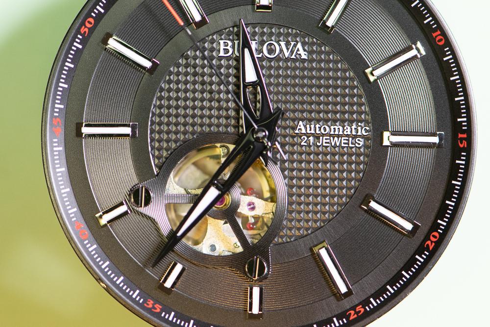
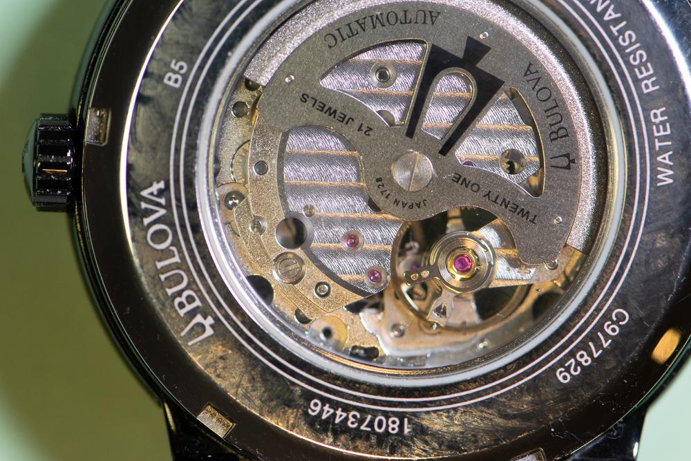
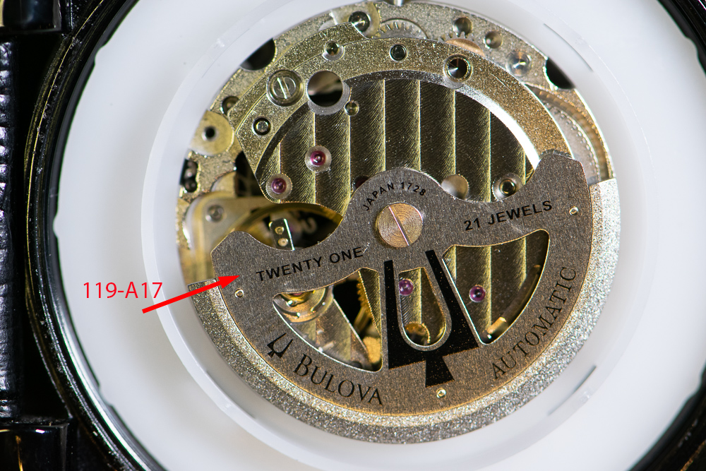
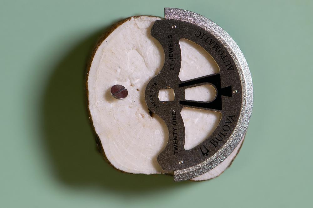
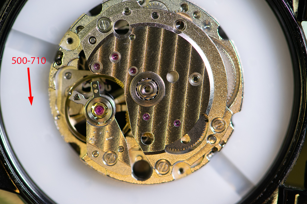
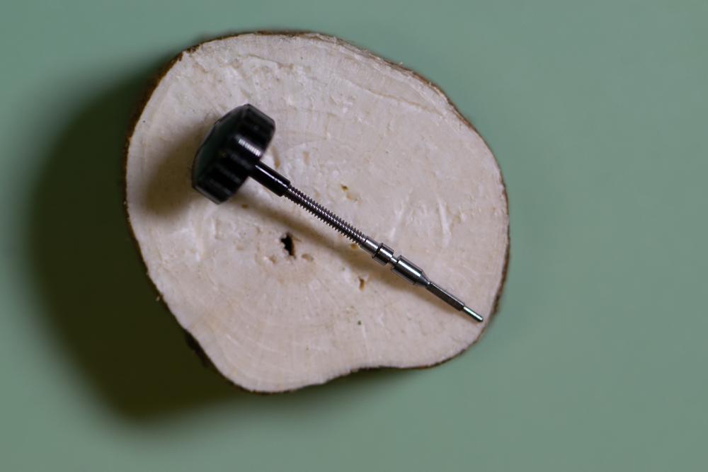
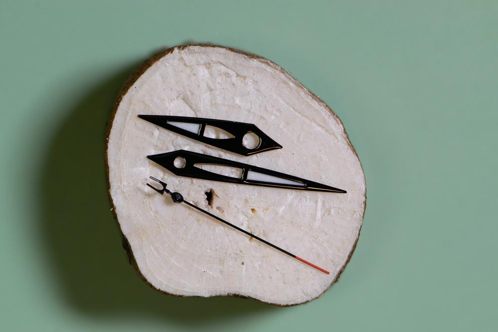
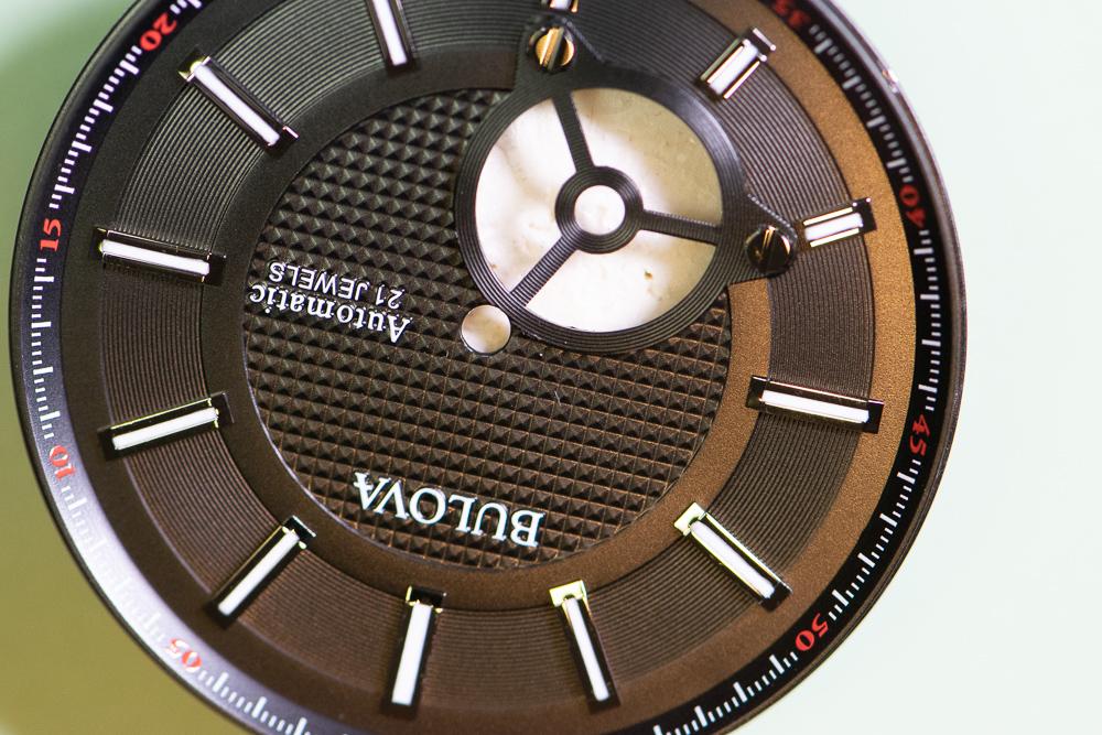
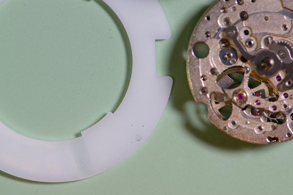
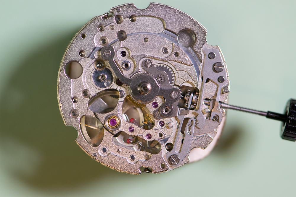
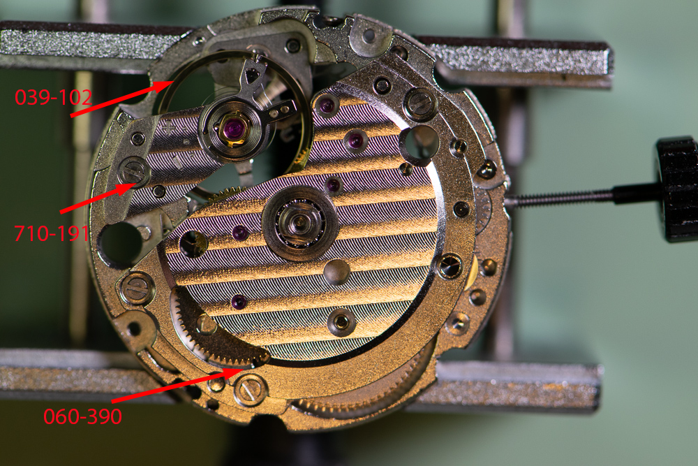
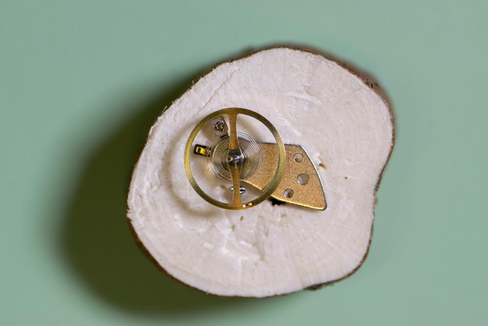
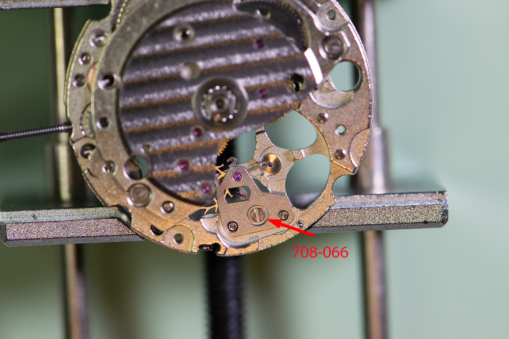
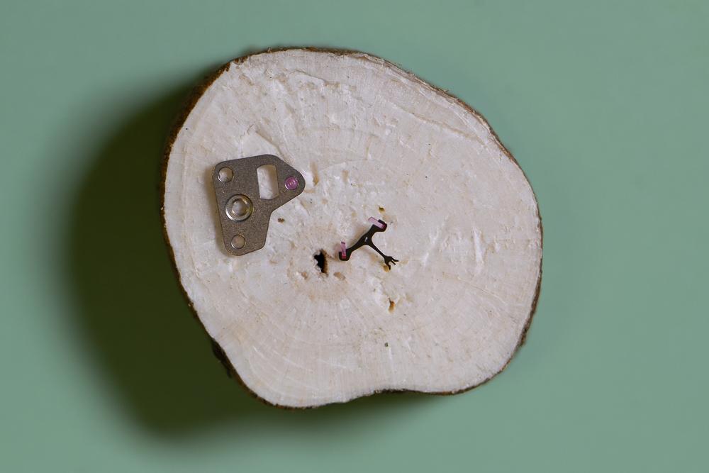
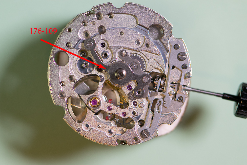
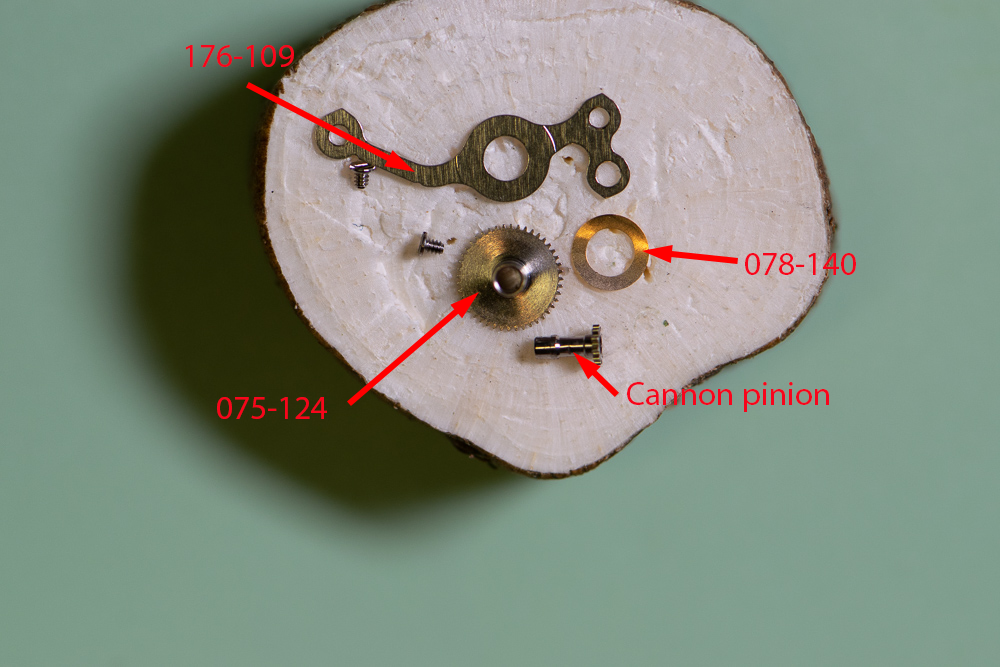
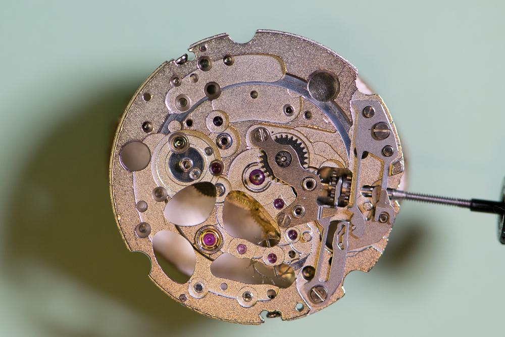
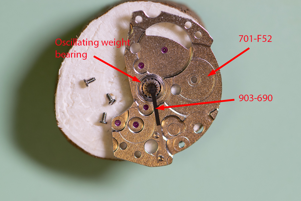
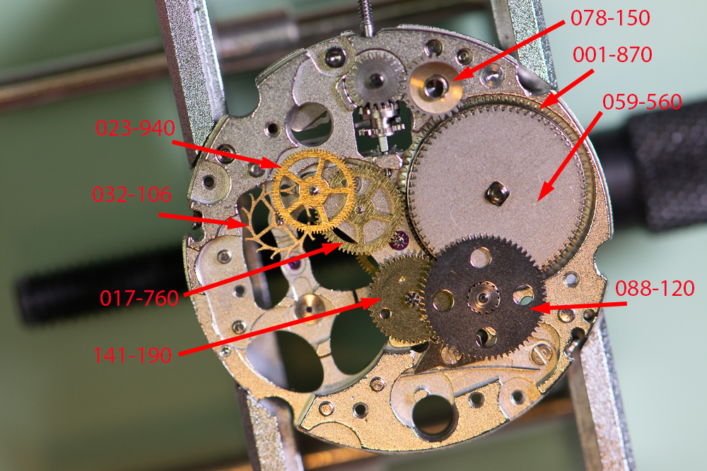
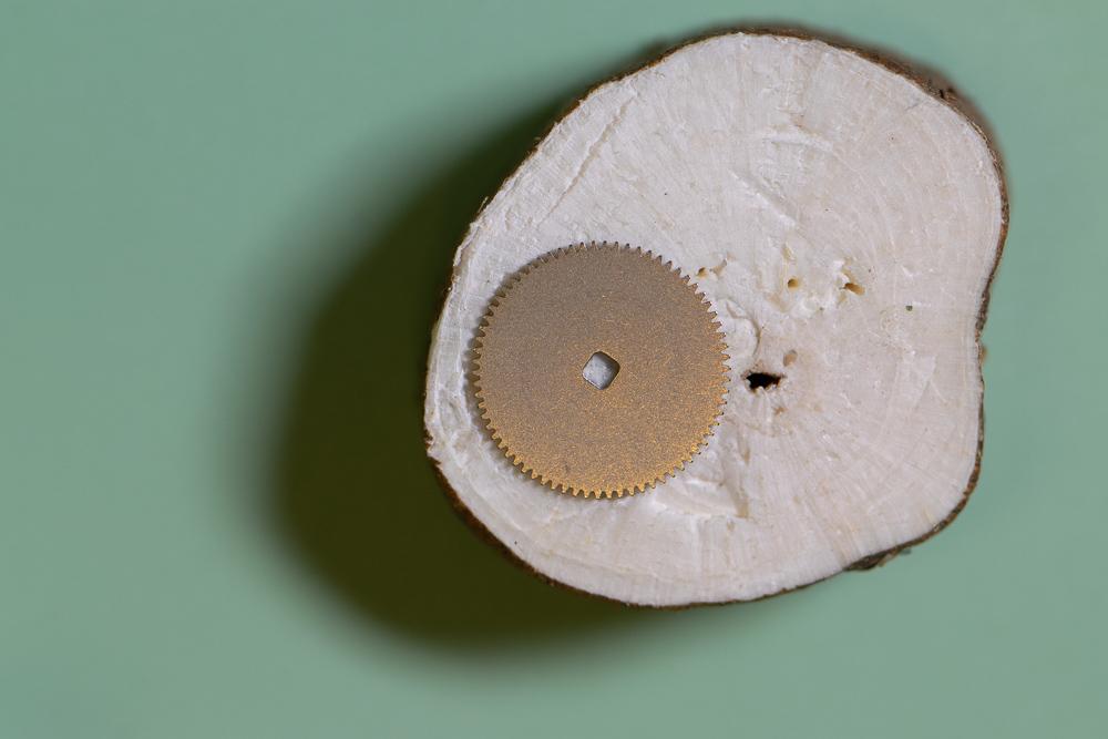
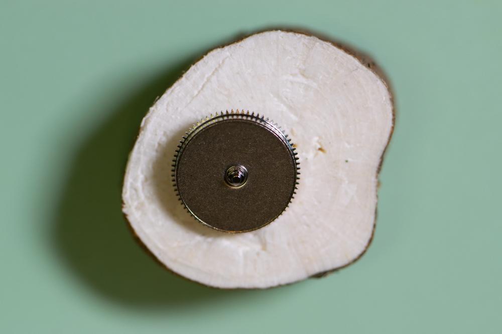
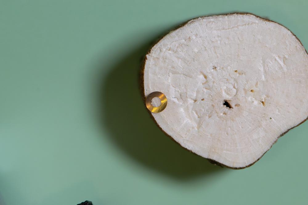
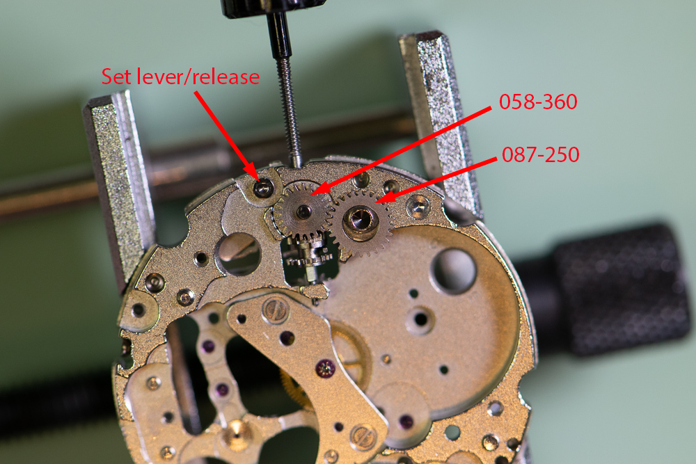
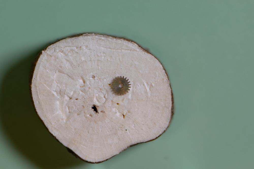
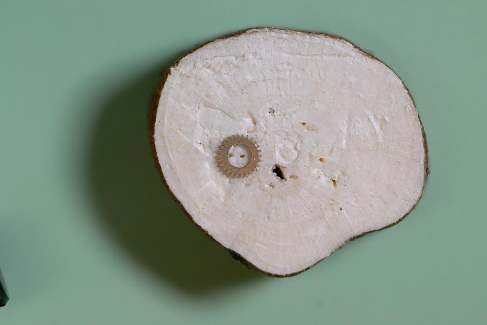
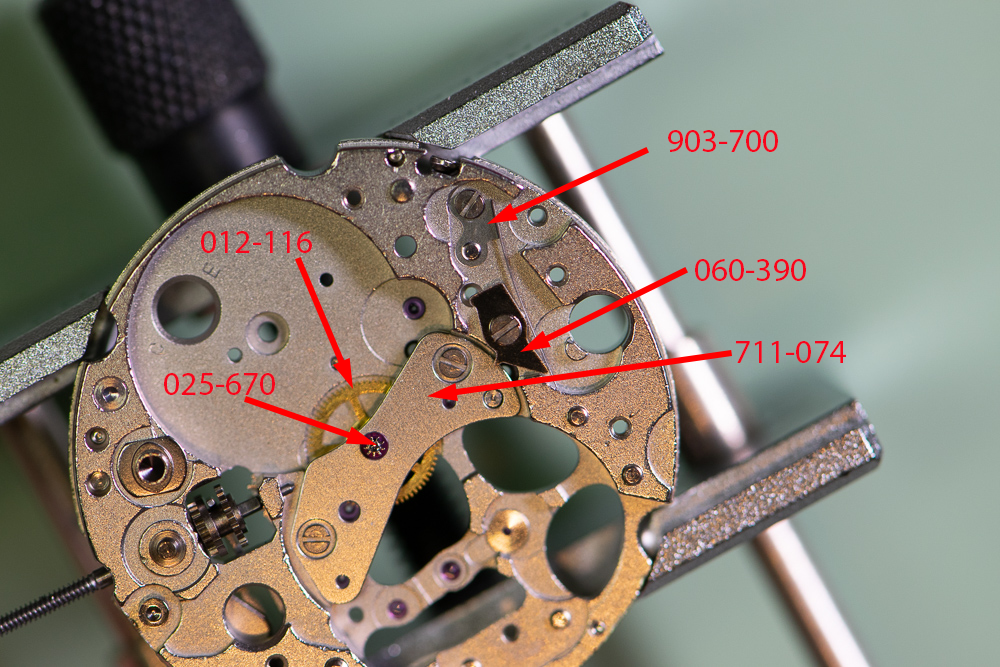
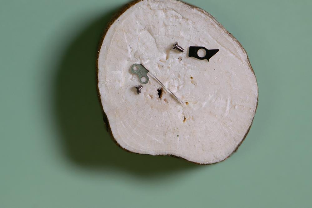
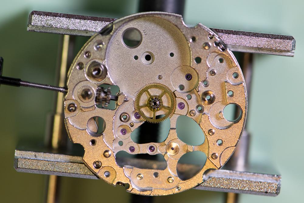
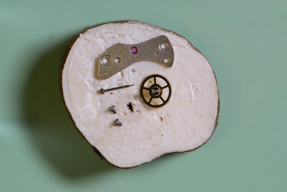
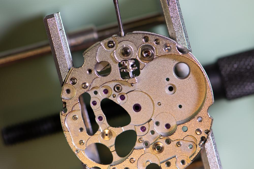
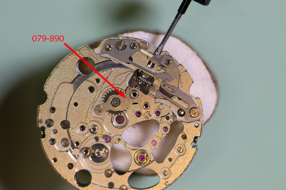
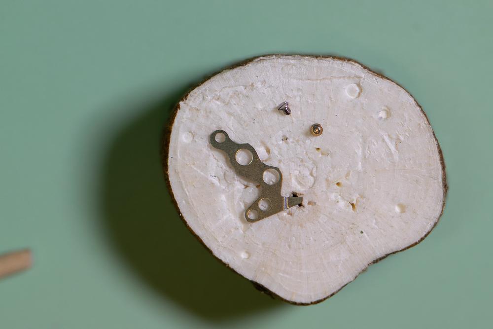
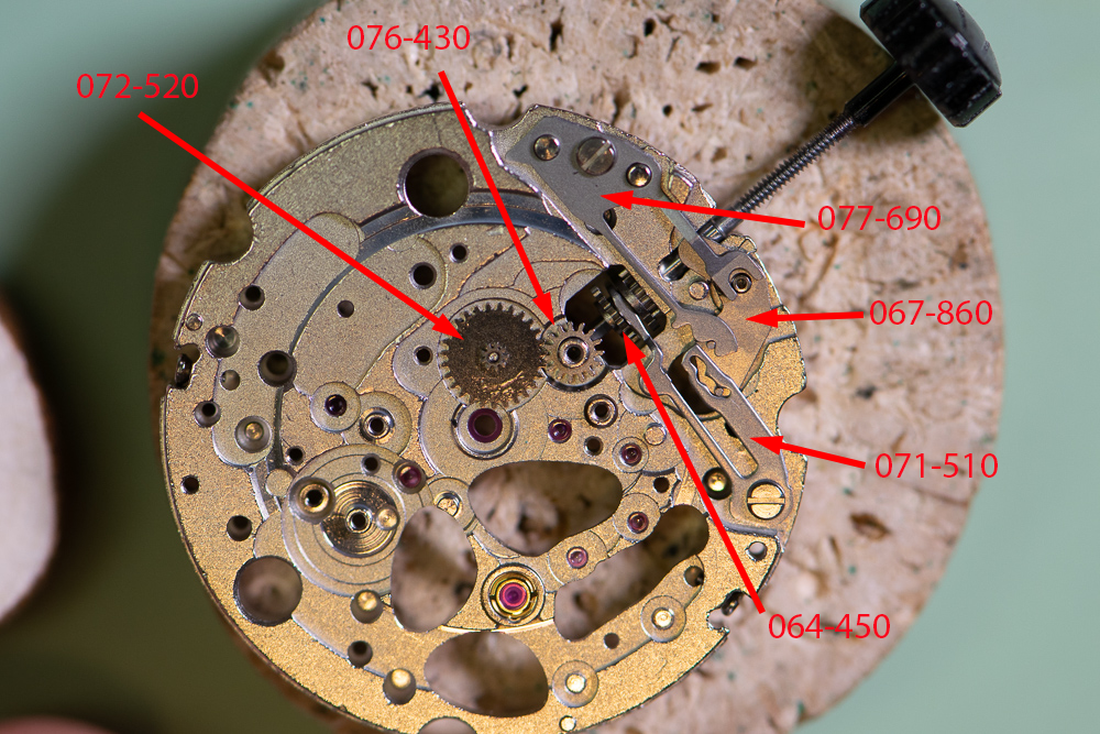
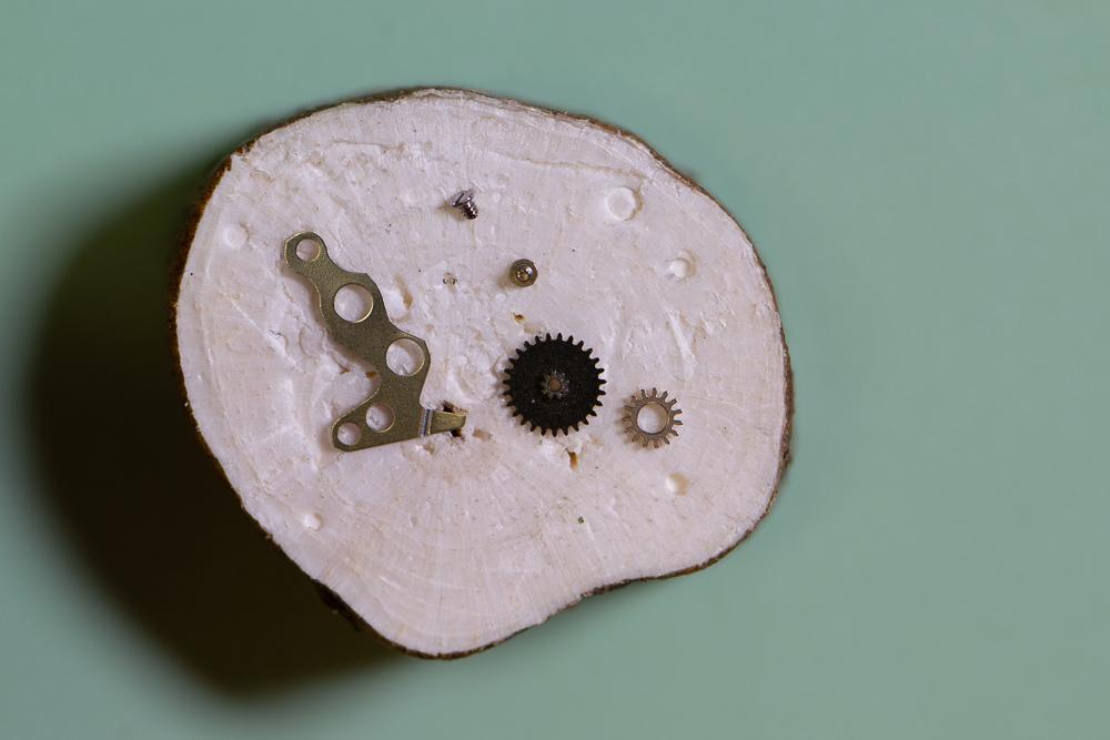
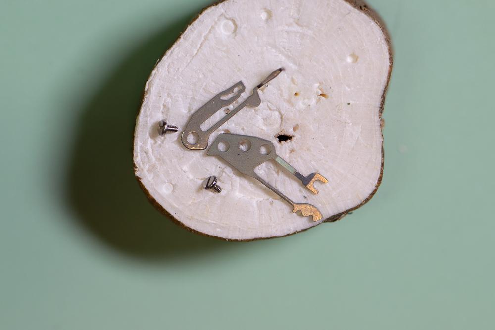
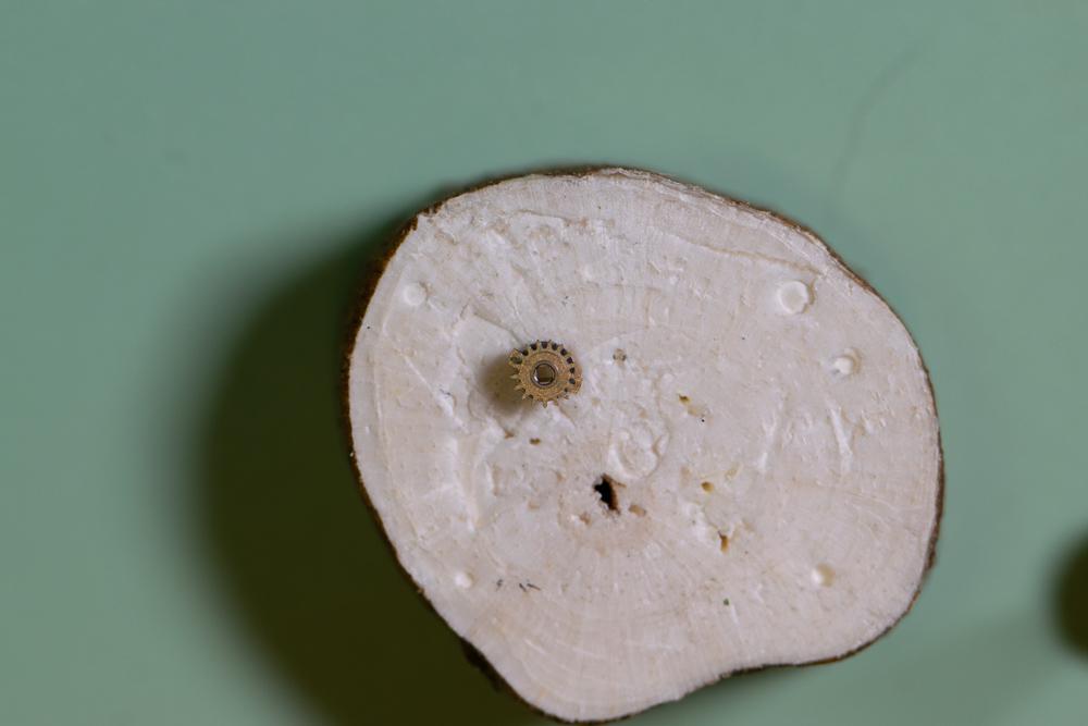
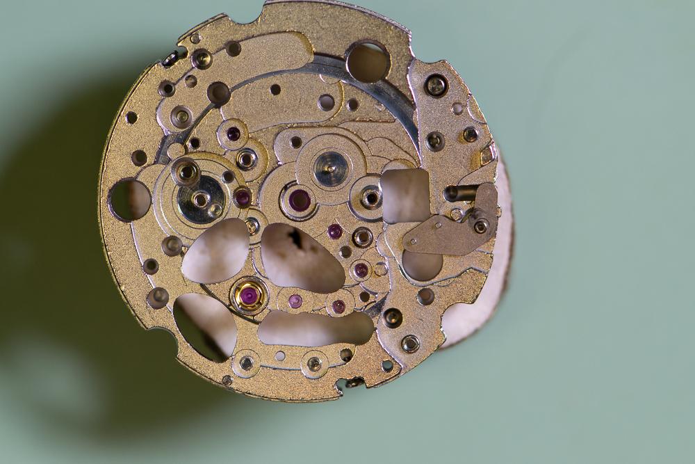
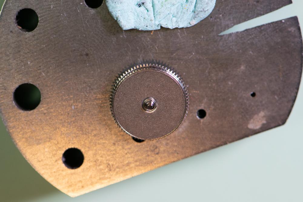
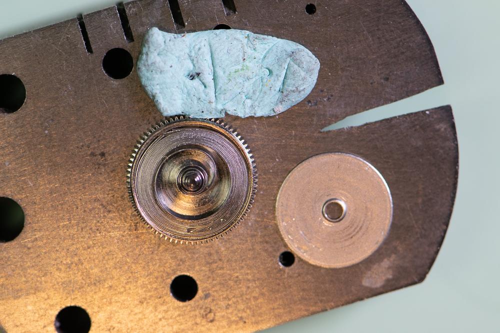
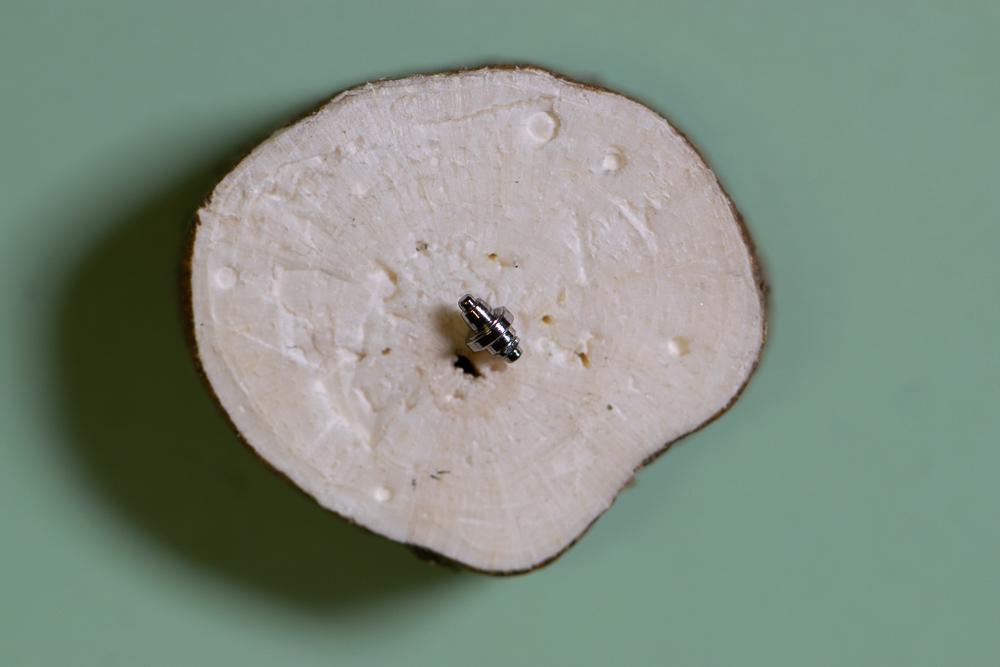
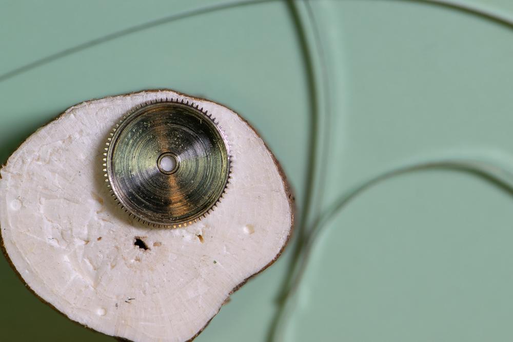
This is a more detailed version of my previous picture-only post for this watch. This Bulova 21-jewel automatic was given to me by a colleague for repair. It was running extremely fast – gaining about 15 minutes per hour. The movement is a Citizen/Miyota 82S0 skeleton. Looking through the clear back it was obvious that the balance amplitude was extremely low. First step was to simply demagnetize the watch to see if that did the trick as it sometimes does. No dice. I then removed the balance and pallets and put a small amount of wind onto the mainspring. The train spun up but as power wore off the escape wheel stopped, then started again several times. It was a very sloppy action. Nothing obvious in terms of loose or cracked jewels or excessive side or end shake that I could see. I decided to disassemble the movement and give it a full servicing. Here is how I disassembled the movement. Where I can I will list the Miyota part number for reference. You can find the parts list here: http://miyotamovement.com/parts_search.php?open=82S0 Figure 1 shows the face of the watch after removing from the case. Note the exposed balance at the 7 o’clock position. Figure 1 – Face Figure 2 shows the clear case back prior to removing the movement. Figure 2 – Case back The first step in disassembly is to remove the Oscillating weight (119-A17. Note that the weight is secured to a bearing that is pressed into the main plate. Unlike many Swiss movements, the screw securing the weight rotates with the weight itself. I used a peg wood stick to prevent the weight from rotating while unscrewing the fastener. Figure 3 shows the weight prior to removal. Figure 4 shows the oscillating weight after removal. Figure 3 – Preparing to remove the oscillating weight Figure 4 – Oscillating weight Figure 5 shows the movement after removing the oscillating weight. The plastic movement holder (500-710) is also visible. This will be removed after dealing with the hands and dial. I also removed the winding stem (figure 6) by pressing in on the setting lever and gently pulling the stem. The location for pressing on the setting lever was clipped from the pic, but it’s a standard setup. Figure 5 – Plastic movement holder Figure 6 – Winding stem After removing the stem, the movement was removed from the case. The stem was then reinstalled to facilitate power let-down, etc. With the oscillating weight removed, it’s a simple matter to lay the movement down dial-up on a piece of pith wood and remove the hands (Figure 7). The dial retaining screws on the side of the movement are loosened (not removed) and the dial is gently coaxed away from the movement by inserting a thin screwdriver blade. Figure 8 shows the dial after removal. Figure 7 – Hands Figure 8 – The Dial The movement holder shown in figure 5 is now lifted off. It is shown in figure 9 next to the movement. Figure 9 – Movement holder ring Figure 10 shows the dial side of the movement. Figure 10 – Dial side The movement is then flipped dial down and loaded into a movement holder for disassembly. The balance (039-102) is removed along with the balance bridge (710-191) as shown in figure 11. Figure 11 – Preparing to remove balance The balance complete is shown after removal in figure 12. Figure 12 – The balance complete Important: Before removing the pallets I need to remove all the power from the mainspring. I do this in the standard way – by applying a bit of winding pressure on the crown while pulling the click (060-390 in figure 11) out of the way with a bit of peg wood and allowing the stem to unwind in a slow/controlled manner. Figure 13 – About to remove pallets With the power let down I can now remove the pallet bridge (708-066) and pallets. Figure 13 shows the bridge prior to removal. The pallets and bridge are shown in figure 14. Figure 14 – Pallets and pallet bridge I probably should have removed the motion work prior to starting in on the balance – not sure why I didn’t. Regardless, we need to flip the movement back so I can remove the motion work from the dial side. The hour wheel is held in place by the hour wheel spring (176-109). Remove the 2 retaining screws and then lift off the spring. The spring is shown prior to removal in figure 15. Figure 15 – Hour wheel spring prior to removal Once the hour wheel spring is out of the way I can remove the dial washer (078-140), the hour wheel (075-124) and finally the cannon pinion (using your favorite cannon pinion removal tool). These parts are shown after removal in figure 16. Figure 16 – Hour wheel spring, hour wheel, dial washer and cannon pinion Figure 17 shows the movement after removal of the motion work. It’s now time to flip the movement back over and start in on the gear train. Figure 17 – After removing the motion work I remove the three screws securing the barrel and train wheel bridge (701-F52) and carefully remove it. Figure 18 shows the underside of the bridge. Note that the seconds pinion friction spring (903-690) was left in place. I didn’t see the point in removing it. You can also see the oscillating weight bearing that is press fit into the bridge. I didn’t mess with this either! Figure 18 – Barrel and train wheel bridge and seconds pinion friction spring Figure 19 shows the detail after removing the barrel and train wheel bridge. First, I remove the reduction gear (088-120) and reversing wheel (141-190). These components are part of the automatic winding mechanism. They are shown in figures 20 and 21 after removal. I make note that the reversing wheel should be installed with the brass side up. Figure 19 – After removing barrel and train wheel bridge Figure 20 – Reduction gear Figure 21 – Reversing wheel Next, remove the third wheel (017-760), fourth wheel (023-940) and escape wheel (032-106). These are shown in figure 22. Figure 22 – From left to right – escape wheel, fourth wheel and third wheel Next, I remove the ratchet wheel (059-560) and the barrel complete (001-870), which sits directly underneath the ratchet wheel. Th.ese components are shown in figures 23 and 24. Figure 23 – Ratchet wheel Figure 24 – Barrel complete Looking back at figure 19, you can see a spring, very similar to a dial washer. This part is called the ratchet sliding wheel spring (078-150). Simply lift it off (figure 25). Figure 25 – Ratchet sliding wheel spring With the spring out of the way I can now see the ratchet sliding wheel (087-250). I remove this part along with the crown wheel (058-360). Figure 26 shows these parts. Ah – finally a picture that shows the setting lever release button I mentioned earlier! Pressing here allows the stem to be removed. I will leave the stem in place for now. Will get to it shortly. Figures 27 and 28 show the parts just removed. Figure 26 – Crown wheel and ratchet sliding wheel Figure 27 – Crown wheel Figure 28 – Ratchet sliding wheel Figure 29 shows the click (060-390) and click spring (903-700), the center wheel cock (711-074), center wheel (012-116) and center seconds pinion (025-670). Technically I believe the center wheel cock should be named the center wheel bridge since it’s secured by more than one screw, but I’ll leave that open for debate. Tension on the center seconds pinion is provided by the friction spring we saw back in figure 18. Figure 29 – Click and spring, center wheel and cock, center seconds pinion Figure 30 depicts the click and click spring after removal. Figure 30 – Click and click spring Figure 31 shows the center wheel in place after the center wheel cock has been removed. Figure 31 – After removal of the center wheel cock Figure 32 depicts these parts after removal. Figure 32 – Center wheel cock, center wheel and center seconds pinion The train side of the movement is now fully stripped. This is shown nicely in figure 33. Time to flip it over and finish off the dial side. Figure 33 – Finished with the train side Figure 34 shows the current state of the dial side of the movement. To get started I remove the minute train cover (079-890). Figure 35 shows this component after removal. Figure 34 – Dial side Figure 35 – Minute train cover I can now remove the keyless work. The components are shown in figure 36. The minute wheel (072-520) and setting wheel (076-430) are removed first. These components are shown in figure 37 along with the minute train cover. Figure 36 – Keyless work components Figure 37 – Minute and setting wheel Referring back to figure 36, the next components to remove are the yoke (071-510) and setting lever spring (077-690). The stem can now be removed and then the clutch (064-450) is free to remove. The setting lever (067-860) was not removed as it’s press button is staked (spread). No sense disturbing this. Figure 38 shows the yoke and setting lever spring after removal. The clutch is shown in figure 39. Figure 38 – Yoke (left) and setting lever spring Figure 39 - Clutch Finally, the main plate is fully stripped. The dial side is shown in figure 40. Figure 40 – Main plate – dial side We can now deal with the barrel assembly (figure 41). Figure 41 – Mainspring barrel complete Using the steel anvil for support, gently press down on the gear teeth to pop the barrel cover off (figure 42). Figure 42 – Barrel cover removed Carefully remove the barrel arbor (figure 43). Figure 43 – Barrel arbor Unwind the mainspring from the barrel (figure 44). Figure 44 – Barrel with spring removed This completes the disassembly of the movement. My next step will be to clean it in the ultrasonic. Will post the reassembly as a new thread.
 1 point
 -
You spend 2 hours assembling a vintage watch, carefully oil everything, drop in the balance and you can instantly see you have obviously missed something else not right. I just did this, watch only has an amplitude of around 140 degrees. I replaced the mainspring so I know that is good, but obviously I am loosing power somewhere. Time to stop tonight, have a whiskey and strip it back down tomorrow and look for what I missed1 point
-
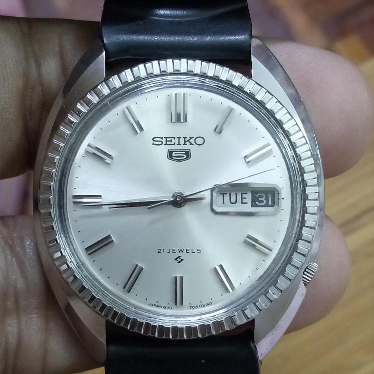
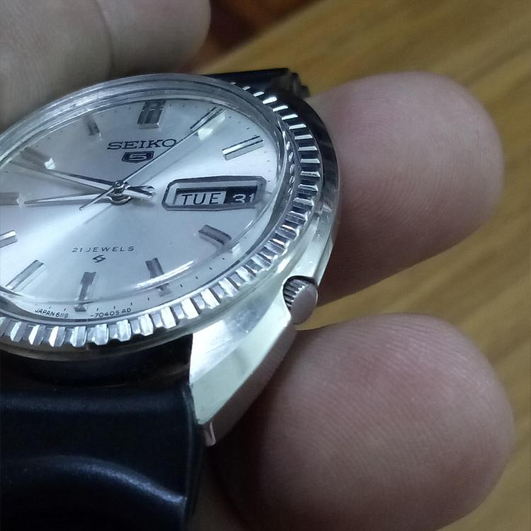
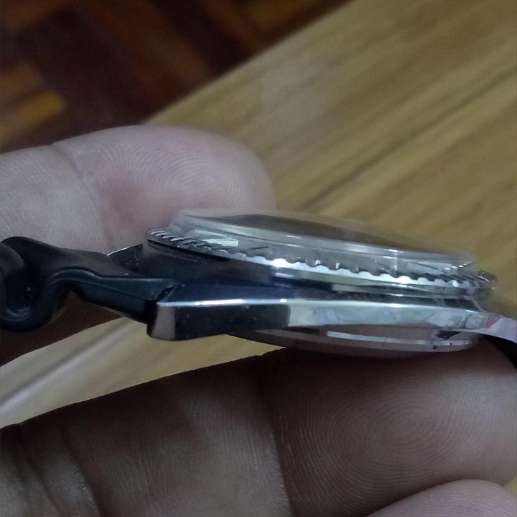
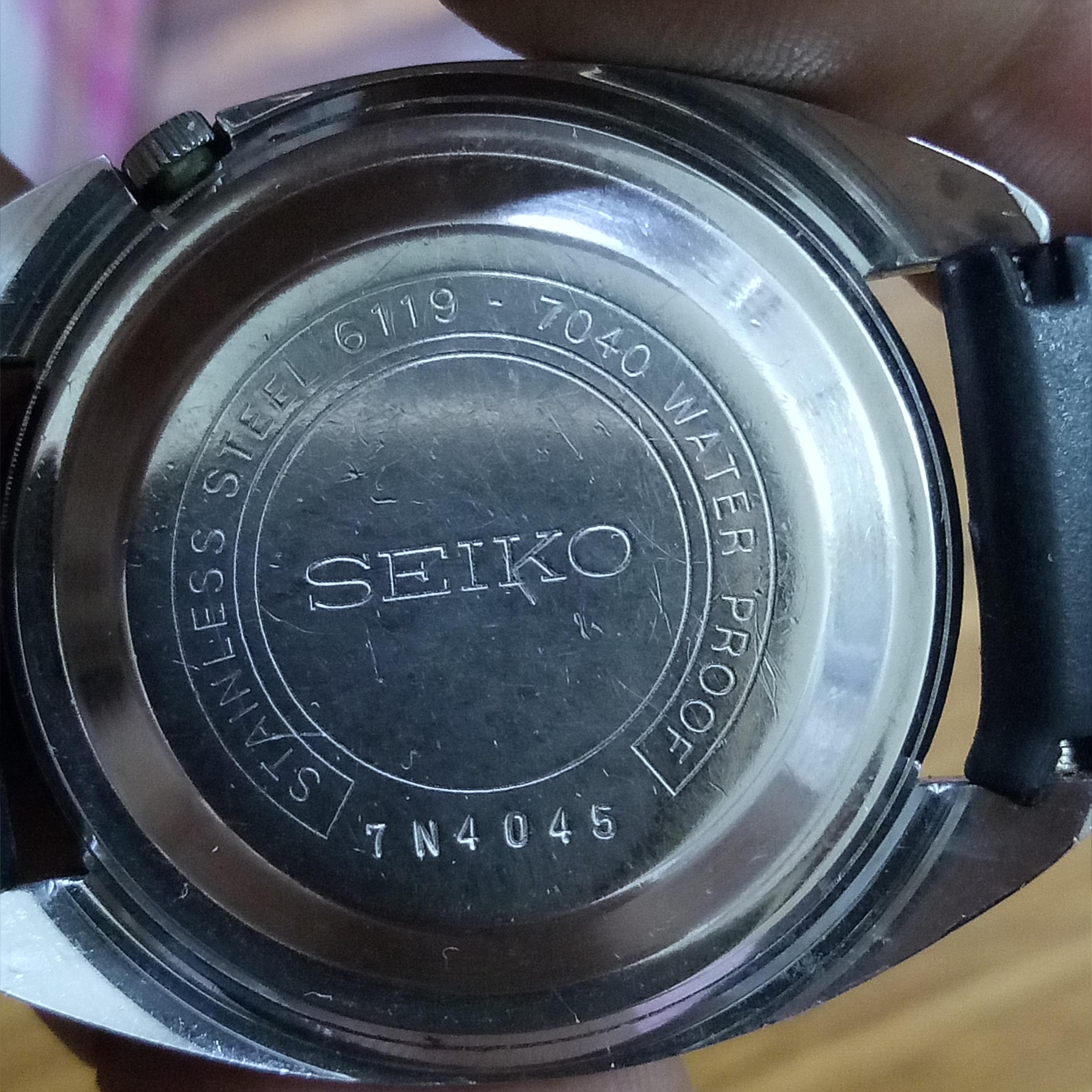
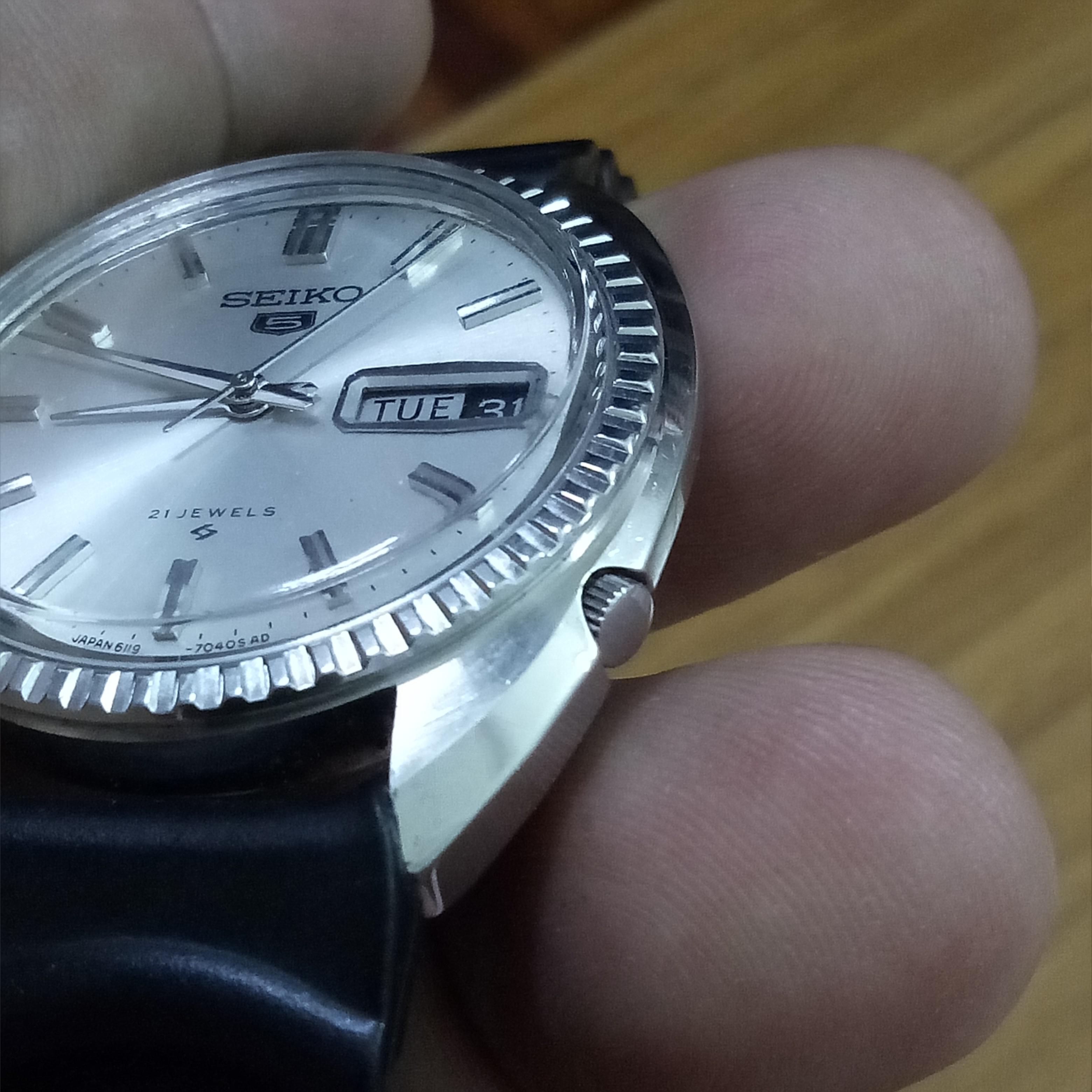
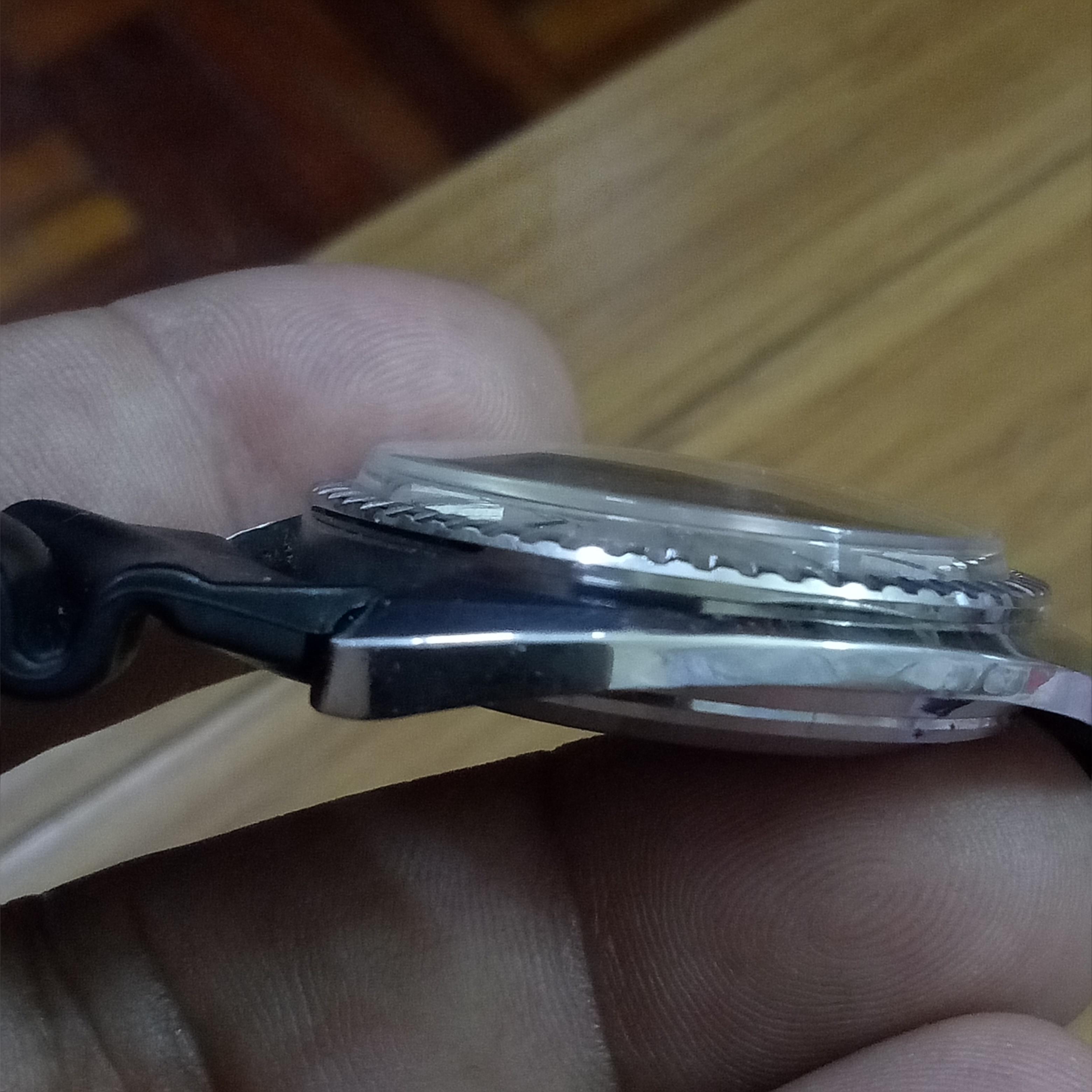
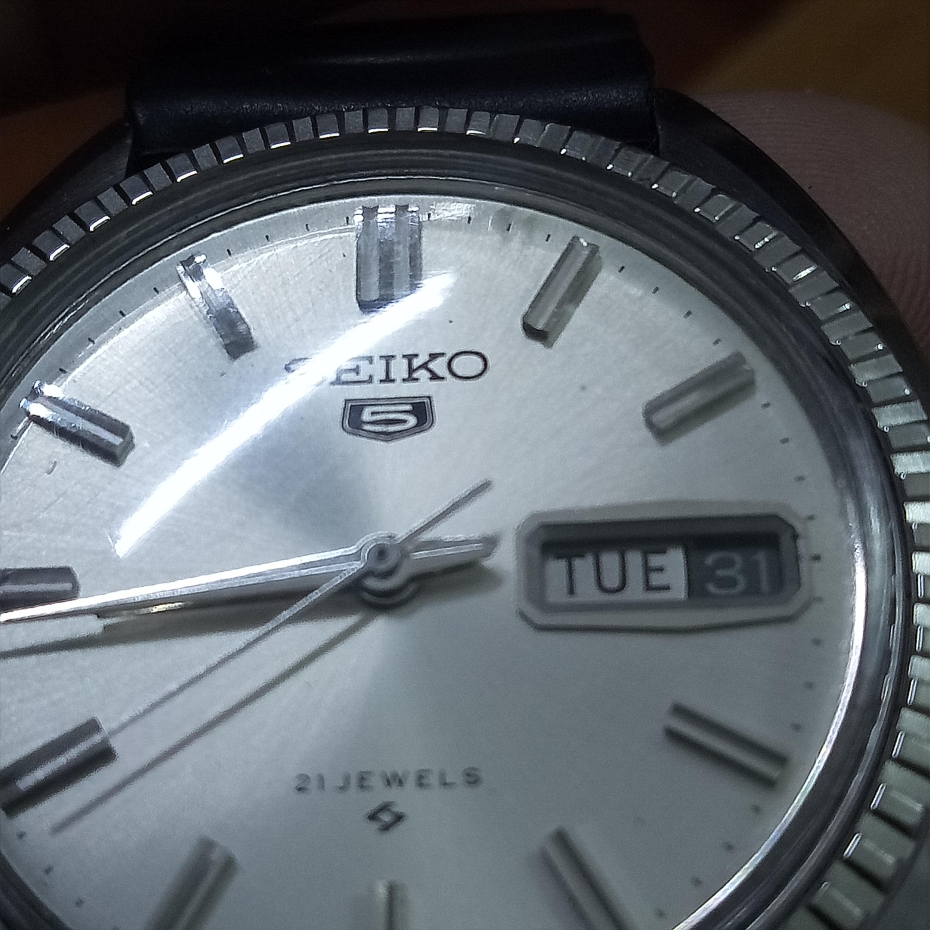
Hi guys.. Sharing some pics of my latest purchase. An early Seiko 5. This was for sale on local facebook page and I got it for MYR177 plus MYR10 for shipping. That's less than USD50 all in. I'm not a fan of these ridged bezels but I was drawn to the clean face as these are getting harder to find. The case back is from Nov '67. Seiko went from the seven digit serial numbers to the six digit ones sometime in '67 so this would be an early one. Oh and a 'proof' case back is always nice! It's a snap back.. Not a front loader. Case looks like its been polished but it's not too bad. Another view of the dial... On most older Seiko's you would find the lume has blackened and this affects an otherwise perfect dial but since this model didn't come with lume it's pretty much perfect. Inside is a 6119 movement... I'm particularly find if this movement and despite the bezel I think this one is a keeper. Anilv

 1 point
 -
But I know that many people clean there movement parts in Zippo or similar. I use Elma and Iso. But not for the balance and pallet fork. Is petroleum ether the same as clean chemical petroleum.1 point
-
I cleaned a Tissot 784-2 hairspring 4 times in lighter fluid and still sticks together. Used a brush and cleaned the hairspring under the microscope with acetone. Let i dry and now it's running good. There are some hairspring cleaning fluids out there. But many of them use tricloretylene which is no good for the health. So i stick with my method1 point
-
1 point
-
Looking out my window I saw my old friend " Batman" the neighborhood cat looking for a dry place to nap. We brought him in, dried him off and gave him a nice can of food.
 1 point
 -
That's interesting because it doesn't look distorted. It actually looks just fine. I can take an oiler and gently separate the coils, and they stay separated until it starts to run, but sometimes, it can tick for a week or two before the utmost coils stick together again. What would be the remedy if not a contamination but indeed distortion?1 point
-
you need to read up or "video up" in the "entry shape" of the lead into the main part of the hair spring. its in all the books AND if you have a "time grapher" (sp) it will tell ypi when thw shape "is best". vin1 point
-
That's because the hairspring is distorted. It takes a lot of magnetism or grease to make coils actually stick, even if these reasons are usually blamed first.1 point
-
Are there any reasons other than oil and magnetism that can foul the coils? @Pip When you have the time, it would be nice to see a picture of the watch itself! I actually have a similar situation with a Poljot 2614.2H movement. The Penultimate HS coil sticks to the utmost coil. I have demagnetized it, and I've just serviced it. I really can't detect any oil looking at the coils in my stereomicroscope but I guess it must be there (noticed I had overoiled the balance end stone, ouch!)1 point
-
Before assuming and pulling, remove hands and check if dial can be removed. In that case the stem release could be under it.1 point
-
I would say that the lighter fluid is just not enough to clean hairspring properly. At least rinse it in acetone and try again. anilv is right, the dangling balance method is not suitable for watches where the balance is somehow covered. My method is to hold the cock and balance together with tweezers and put them where they have to be (approximately). After that I can manipulate with the cock only and put everything in place. For other watches the dangling method works just fine.1 point
-
You can also buy an 8mm die (tap and die) and run it along the threads to clean and straighten things out Sent from my iPhone using Tapatalk Pro1 point
-
I have used the edge of a screwdriver very carefully on the threads, where there is lots of dirt and a fake metal cleaning pad does not work. Lots of oil though. Sent from my iPhone using Tapatalk Pro1 point
-
Hi Neil, Welcome to this nice forum. There is a lot of help here. Mark Lovick runs courses in watch repair and de Carles and Fried`s books are an excellent treatise if you like literature. There is a lot also on the web. All good wishes to you, Mike.1 point
-
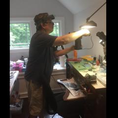
Hi Dave :) First, don't get focal length confused with zoom. The zoom, on a microscope, refers to the degree of magnification, while the focal length is essentially how far the bottom lens is from the object you're working on. So when you FOCUS the microscope, it moves up and down, usually on a rack-and-pinion mechanism. When you ZOOM the microscope, the internal lenses change their configuration to increase or decrease the magnification factor, while the microscope itself doesn't move. And there's no need to change lenses with a zoom system. Now, if you want to mount a microscope on a long arm (similar to the operating microscopes I use in surgery), you need a very strong mounting arm (the ones we use are multi-jointed on a VERY heavy stand) with enough counterweight to balance against the weight of the microscope itself PLUS the distance it is mounted away from the mounting point of the arm. If you see what I mean. The longer the mounting arm (i.e. the further away from the microscope itself the base of the arm is) the more counterweight you would need, OR a totally rigid mounting point. Now where a lot of the expense arises in brands like Olympus, Zeiss (the ones I use at work are Zeiss), etc is in the optics that are designed to have a LONG focal length (using the term to mean working distance). You will know from a watchmaker's eyeglass that the higher the magnification, the shorter the focal length, or to look at it another way (no pun intended) the closer you have to be to the work. Very expensive operating microscopes have working distances measured out to about 500mm or more, while maintaining magnifications up to 40x. And I can tell you, one cup of coffee before using one of those and your hands appear to shake like an earthquake! The cheaper brands won't have the long working distance, but those advertised as stereo dissecting microscopes will have a reasonable working distance. The ones I linked to all have working distances of around 100-150mm at most. But that is probably more than enough for what you need. Is there any particular reason you want it on a long arm? The reason I ask is that there is usually plenty of room to work on watch movements etc under one of those dissecting microscopes. The LapSun one that our neurosciences lab uses has the benefit of a cold-light LED ring system as well. That's the one I think I'll get for myself. But I don't need it on a long arm. Having just re-read your question (and apologies for the long-winded answer), the answer is no, you can't change the working distance of the microscope from say 70mm to 250mm. I assume you're talking about the vertical distance between the object and the lower lens - that's what is meant by working distance. If you DID want to mount the microscope on a longer arm, you'd need to mount the rack-and-pinion focusing system with the microscope, but also make sure that the microscope at half way up the rack is in focus. That gives you adjustment both ways. The other thing to remember is that the eyepieces of microscopes like these are angled towards you, and you need to have the instrument at a comfortable height for you to lean slightly forward and have your eyes on the eyepieces. If you don't have that at a comfortable height, you will soon get a very stiff neck and a headache! (Said he, speaking from bitter experience). Hope that all helps, and makes some kind of sense. :) -- Pete, Brisbane ============1 point


.jpg.6225a64433578a11e0218b27c20b13f5.thumb.jpg.d82b0cd1e370f3a3a59a06afa957d184.jpg)