Jump to content

Recommended Posts

Posted

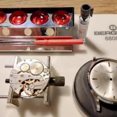
Today I had a look at an IWC 66 19'''H6; produced around 1916/1917.The problem was the winding didn't work at all. 
So on with the task to strip the movement and very soon one cold see the problem was in the Geneva Stop-Work. 
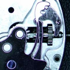
The stop finger attached to the barrel and arbor wheel had snapped into two pieces and wedged in between the barrel and the bridge.
The mainspring was broken too.
I know Urdelar.se has a complete barrel with finger and Maltese cross, but I only need the finger piece. Do anyone know where to
find one of these without having to harvest one from a complete barrel?
I know the watch works without this component and obviously one can break the finger piece and mainspring even with it attached.

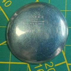
Attaching some photos of the movement and broken finger piece.

Finger piece.jpg

IWC_66_Back.jpg

IWC_66_DialSide.jpg

Posted (edited)

How easy would it be to make?

The square hole looks like the tricky bit. Would a square needle file work, or would you need a square broach. Well the square hole and the fact that the piece is tiny, and probably hardened.

What scale are we talking here? The size is not easy to judge from the pictures.

I guess it all comes down to how much work is involved, if you have to start making your own broach, and tempering things by hand, it might be too much trouble.


Edited by AndyHull
Posted


40 minutes ago, AndyHull said:

How easy would it be to make?

The square hole looks like the tricky bit. Would a square needle file work, or would you need a square broach. Well the square hole and the fact that the piece is tiny, and probably hardened.

What scale are we talking here? The size is not easy to judge from the pictures.

Guess I just have to fire up the small Mill someday and try to make one .
I have seen that square broach when I was admiring that guys work making a clock, liked that series a lot, but the dimensions are quite different here.
The radius of the finger is 2.5 mm , the finger sticks out approximately 1 mm . The square hole is 1.5 mm so quite different from a clock.

Then one needs to make a smal radius on the foot of the finger. One just have to admire the work they put down on these once upon a time
Maybe use a steel with less carbon in it so it doesn't get as harden as the original, might get less brittle.

Posted (edited)

So the whole piece is less than 5mm in any dimension. How thick is it?


I suspect that with a little patience, some good magnification and some small drills and files, it might be possible to make, but certainly purchasing one is a less painful option, if it is available.

Brazing or silvers soldering it back together I presume is not an option either?


Edited by AndyHull
Posted

You could make one. The square hole will be the hardest, start off by drilling a hole and expand it by using escapement files until you get to the right size square.   

Posted

Can you silver solder it back together, as long as its a clean break with careful pinning it might be possible to silver (hard) solder it back together.


Posted (edited)

silver solder is probably what I'd try but is the piece hardened?  that might squash the silver soldering idea.  As for making a part, I've made broaches as shown above, but would think it pretty much impossible at 1.5mm.   I think the whole job is a filling job, given how short the section is, even if the square was larger you'd file a dozen parts before you got one broach done.

One way to get an accurate fit is to use a thin coat of prussian blue (basically like oil paint that doesn't dry) on the mating part.  On a trial fit, the blue marks where you are tight and lets end with a filled fit with little slop or clearance.   On the outside, no great ideas.  Its complicated obviously in that can't turn the OD as the pip would interfere.  Turn the OD, then SS on a piece and file?  Or just file the whole outside?

Another trick to make square holes is to SS two pieces together, i.e. a U and a flat or two "L"'s soldered together make an square hole.  Make the square then finish the outside.  Not sure its applicability on this piece, but worth mentioning as a way to get a square hole


Edited by measuretwice
Posted

Whether it is hardened or not, rather depends on what its purposes is, I suppose.

Drag a file over it and see how easy it is to mark. If the file glances off, or barely marks it, then it is hardened, otherwise.. not.

If not hardened, then silver soldering might be a fix, but if hardened, then you would almost certainly need to make or find a replacement.


Posted

Just got back home from a Sunday dinner.
The part is hardened like a knife edge, the file don't bite on it.


But as everyone knows a Sunday dinner is the mother of all ideas,especially when you suffer from a restless brain syndrome.
I took a deep dive into my sea of never ending spare parts and found what I was looking for, A ratchet wheel with the exact dimensions of the square hole. So for now I just tried to grind of the teeth to see how hard the material is to work with and it seems reasonable.
Tomorrow I will continue working on it with proper tools and less food in my belly.
Thanks for all the inspiring suggestions, guess when it comes to rare old movements the solution is the file and the lathe. 
 

Prepared Ratchet wheel.jpg

  • Like 1
Posted (edited)

You could even simply superglue it on. A little heat, less then you need to melt solder, and the superglue will let go, or pop it in some acetone (nail polish remover).

Edited by AndyHull
Posted (edited)
On 1/6/2019 at 10:23 AM, oldhippy said:

You could make one. The square hole will be the hardest, start off by drilling a hole and expand it by using escapement files until you get to the right size square.   

Yes it is actually probably was the easiest way, now the winding is effectively blocked as it should so now you can wind it to IWC specs..

Here is the new finger fitted onto the arbour.

Fitted.jpg

Edited by HSL
  • Like 1
  • Thanks 1
  • Recently Browsing

    • No registered users viewing this page.
  • Topics

  • Posts

    • A helpful way in aid of assembly is to place all the wheels in their respective places, place to plate on the top and fit a couple of the nuts onto the pillars. This stops all the wheels wobbling about as they are lightly held by the plate, you can manoeuvre the pivots into their holes, using a tool , usually home made or can be bought on eBay. I made my own. As the pivots align and fall into place screw the nuts down a bit to keep up the tension on the plate untill all wheels are in place then tighten down sufficiently to keep the plate in place whilst checking the end shake on ALL wheels and their location when all is good only then tighten down the plate.
    • I'd say my Pultra 10 lathe. It is just so well made and everything fits so tightly together.
    • Welcome to the forum, enjoy. 
    • Yes, the specific old tools do exist, but may be having one is not needed as they are not cheap, and also You will be able to do without it well enough. My advice will be to use regular depthing tool and adjust it for the exact distance between pallet fork and escape wheel bearings from the watch. Then remove the shellac from the pallet that now doesn't pass the ew teeth and move this pallet in. Then put the pallet fork and ew on the depthing tool and check how they lock. They should not lock when the pallet is in, but You will little by little move the pallet out and locking will appear. Then move just an idea out for reliable work and apply shellac, then check if things are still the same. You have to observe where the teeth fall on the pallets - it must be just a little below the edge between impulse and rest planes. Then You must check how everything behaves in the movement This Potence tool is so ingenious, but actually, the traditional way to do the things is much more simple. Arrange the parts not on the pillar plate, but on the cover plate. Only the central wheel will remain on the pillar plate, secured by the cannon pinion.
    • There is a tool that was made for setting up and adjusting escapements of full plate watches.  There were two styles, the picture below shows both of them.  The lower tool held a movement plate and the vertical pointed rods were adjusted to hold the unsupported pivots of the lever and escape wheel.  There was also a version of this tool that had 3 adjustable safety centres so that the balance pivot could be supported by the tool :  The other version I’m aware of is the Boynton’s Escapement Matching and Examining Tool came as a set of two or three clamps that gripped the watch plate and held the safety centres for the pivots : These do turn up on eBay from time to time.  For some escapement work, you can set up the parts in a regular depthing tool, with the centres set according to the distance between the corresponding pivot holes on the movement.  I hope this helps, Mark
×
×
  • Create New...