Jump to content

ETA 2893-1 Service Walkthrough - Part 1 - Disassembly


Recommended Posts

Service Walk Through – ETA 2893-1 / Hamilton Khaki: Part 1 - Disassembly


This is part 1 of my service of a Hamilton Khaki – dual time zone automatic based on the ETA 2893-1 movement. I purchased the watch on eBay and it runs for a short time then stops. Looks like it could use a good cleaning.

Note that the part numbers in the images and text are consistent with those found in the ETA technical document for this movement. Disassembly of this movement is quite straightforward. The only "special" tool you need would be an oscillating weight bolt tool - and you only need this if you intend to remove the ball bearing assembly from the oscillating weight, which really isn't required. In this tear down I do use the tool - only because I recently acquired it and wanted to see how it worked :)

Off we go....


1.jpg

The dial shows evidence of some sloppy workmanship in the watch's past – several scratches from prior hand removal.


2.jpg

Here you see the back of the 2893-1 with its automatic rotor - nicely signed Hamilton.


3.jpg

Preparing to remove the hands – with a safety sheet in place.


4.jpg

After removing the dial, remove the dial support ring. This ring keeps the dial the proper distance from the second timezone disc. Without it, the disc will rub against the dial.


5.jpg

Remove the second timezone disc from the center. This is a bit tricky as there’s no obvious place to grip it. I used two very small screwdrivers on each side to lift the indicator straight up. Be careful not to scratch it!

6-1.jpg

Disc removed.  Note the following parts: Hour Wheel (42); Hour Indicator Driving Wheel (43);  Corrector Setting Wheel (44); Additional Indicator Maintaining Plate (41)


7.jpg


Pop off the dial washer – note that you cannot simply lift the hour wheel (42) off at this point. It is held in place by the hour indicator driving wheel (43).


8.jpg9.jpg10.jpg

I remove the hour indicator driving wheel (43) followed by the corrector setting wheel (44).

11.jpg


The hour wheel (42) is now simply lifted off, followed by the additional indicator maintaining plate (41).


12-1.jpg

Next components to remove are the Date Indicator Maintaining Plate (40) and the Minute Train Bridge (35).

13-1.jpg

14-1.jpg


We move on to remove the Intermediate Date Wheel (39). The Date Jumper (38) has also been exposed when we removed the maintaining plate, so we remove it. Finally, we remove the Date Indicator (37) and the Date Indicator Driving Wheel (36).

15.jpg

16.jpg

17-1.jpg

Now on to some of the motion and keyless work. We remove the Minute Wheel (34),  Cannon Pinion with Driving Wheel (33),  Double Corrector (32) and Date Corrector Intermediate Setting Wheel (31).

18.jpg

19.jpg

20-1.jpg

21-1.jpg


Before dealing with the rest of the keyless work, we flip the movement over and remove the automatic work. After removing the 3 blue screws we lift the entire unit up gently by the Oscillating Weight (28).

22.jpg

23-1.jpg


With the automatic work out of the way – I notice that the Stop Lever (Hack) is missing! Will try and source one.


24-1.jpg

Back to the automatic work. Removing these 3 screws will allow the oscillating weight to come off the Automatic Framework (21) and its components.

25.jpg

25.1.jpg

26-1.jpg


Using the appropriate Bolt tool (pictured with the red handle) – I remove the Oscillating Weight Bolt (28-3) and free the Ball Bearing (28-2) from the Oscillating Weight (28-1). There was no compelling reason to disassemble this portion of the movement.


27-1.jpg

With the Oscillating Weight out of the way, remove the Auxiliary Reverser (27).

28.jpg

29-1.jpg

Flip the unit over once again and remove the screw and Automatic Device Lower Bridge (26).


30-1.jpg

Remove the Reverser (25), Reverser Wheel (24), Reduction Wheel (23) and Intermediate Reduction Wheel (22).

31.jpg

32.jpg

A view of the underside of these components


33-1.jpg

Remove the single screw and gently lift off the Balance Assembly (20) with the Balance Complete (19).

34.jpg

35-1.jpg

Carefully let the power down by releasing the Click (12-6) and slowly letting the crown wind down.


36-1.jpg

 Remove the Pallet Bridge (18) and Pallets (17).


37-1.jpg

Remove the Train Wheel Bridge (16).

38.jpg

39-1.jpg

Remove the Fourth Wheel (15), Third Wheel (14) and Escape Wheel (13).

40.jpg

41-1.jpg


Remove the 3 screws and the Barrel Bridge (12)

42.jpg

43-1.jpg


Flip the bridge over and lift off the Ratchet Wheel Driving Wheel (12-2)


44-1.jpg

Remove the screw and the Click Plate (12-7), followed by the Click (12-6), Intermediate Ratchet Wheel (12-5), Intermediate Crown Wheel (12-4) and Crown Wheel (12-3). Note that the Intermediate Crown Wheel is under the Click Plate. When I removed the plate, the wheel was stuck to it due to some old oil.

45.jpg

46.jpg


Here you can see the Intermediate Crown Wheel as it was stuck.


47-1.jpg

This shows the proper placement of the wheels.


48-1.jpg

Remove the Ratchet Wheel (11), the Mainspring Barrel (10) and Intermediate Wheel (9). Note the scrap of tissue that found its way onto the movement. I was so focused on taking pics that I didn’t notice J

49.jpg

50.jpg


Pop the lid off the barrel.


51.jpg

Remove the mainspring arbor


52.jpg

And finally, remove the mainspring


53.jpg

The movement side is now completely bare. Let’s flip it over and finish off the keyless work.54-1.jpg


Unscrew and remove the Setting Lever Jumper (8), Yoke (7) and the Setting Lever (6)

55.jpg

56.jpg

57-1.jpg

Remove the Date Corrector Operating Lever (5), Winding Stem (4), Winding Pinion (3) and the Sliding Pinion (2)

58.jpg

59.jpg

All stripped down


60.jpg

Ready for the Ultrasonic!!!


Hope you enjoyed this.


Edited by sstakoff
  • Like 1
  • Haha 1
Link to comment
Share on other sites

You.uve done an great job and your photos are excellent.  Unfortunately your captions don't all match up with your illustrations.  It would be a good idea to correct this and re-post.  The original can then be deleted.

Link to comment
Share on other sites

1 hour ago, Geo said:

You.uve done an great job and your photos are excellent.  Unfortunately your captions don't all match up with your illustrations.  It would be a good idea to correct this and re-post.  The original can then be deleted.

That figures! Was a bit of an operation trying to coordinate the offline text with images. I will sort it out today at some point!


Link to comment
Share on other sites

  • 3 years later...


  • Similar Content

  • Recently Browsing

    • No registered users viewing this page.
  • Topics

  • Posts

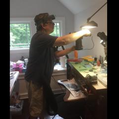
    • Moved in. Now working out the best place to have things so moving around the room makes sense. The wooden movement testing rig may end up being suspended from the roof with some pulleys and ropes that I salvaged from some alfresco blinds that we replaced. I always seem to salvage things from things we scrap thinking, "I have an idea what I can use these for." I hope I'm not the only one that does that. My wife hates me for it. "What are you going to do with all this crap?" Anyway, here you go. If anyone has suggestions for workflow around a room, speak up. All Ideas are appreciated. The bench on wheels will carry either a laptop or my Samsung table for using with the little camera that is on the tripod for photos while dismantling etc. The small bar fridge in the corners going to have water etc in it and I might move the coffee maker from the kitchen out there as I am the only one that uses it. I want to get an ultrasonic cleaner so I may set up some sort of cleaning rig in front of the glass of the sliding door. Where the grandmother clock is currently standing. I'm hoping that I will be able to transition my working area, which is the table that the stool is sitting in front of, fairly easily between clocks and watches. I'll be doing my best to make sure that tools for each are separatedwhen stored. Logistics. I'll have a bit of wall space for being able to hang clocks if I find some that I wish to keep or hopefully at some time to be able to hang customer clocks for monitoring after servicing/repairs. The clock on the left in the blue pillow slip and the grandmother clock are earmarked for  Jarryd and his wife, Sara. He helped me move the benches in today. And then went on to tell me that ticking clocks drive him nuts. Who doesn't like the rhythmic ticking of a clock? I have a green pad for adding to the bench for a working surface. It is not a cutting mat or one of the Bergeon mats. It is actually a green desk writing mat. Was really cheap and will do exactly what I want, I think. I also have to get the sparkies back that put our new stove in to put some power points on the walls behind the benches. Hopefully this is all going to go well. I'm excited about it. It'll beat having to live out in the garage doing it. The other thing I have to do is cut a circle or square of plastic to go over the bouncing watch or clock part black hole in the middle of the floor. I would pretty much guarantee that anything that sproings off the bench would end up going straight down that drain. 😄     
    • So leave off the seconds. Stand the movement on its edge, its the dial edge that rests on the pad ( either rubber or cork , something that wont slip ). Use a finger of your left hand to hold the movement upright,  right hand presses the release and flicks out the stem. I do it this way so i can see what I'm under a microscope. But you could hold the movement between two fingers of your left hand, its the right that has to manipulate the stem out by pushing the release and flicking out the stem with  right ring finger nail. Sounds more complicated than it actually is. I guess you could fix a push pin to something solid, then all you need to do is push the release against the pin, leaving your right hand completely free to pull the stem out.
    • Try putting everything back together and closing the back cover. I think one of the two springs has to contact the metal casing to ground the casing. So when you press the button, it will touch the contact on circuit board and close the circuit.
    • Yes, the seconds hand is the longest and goes almost to the edge of the dial. I can’t quite picture it how you do it on the rubber pad
    • A don't think so it leaked or damaged it because the watch itself works it just the buttons ain't working not connecting with the circuit board have taken more pictures of where the buttons makes contact with the circuit board.
×
×
  • Create New...