Search the Community
Showing results for tags '2893-1'.
Found 3 results
-
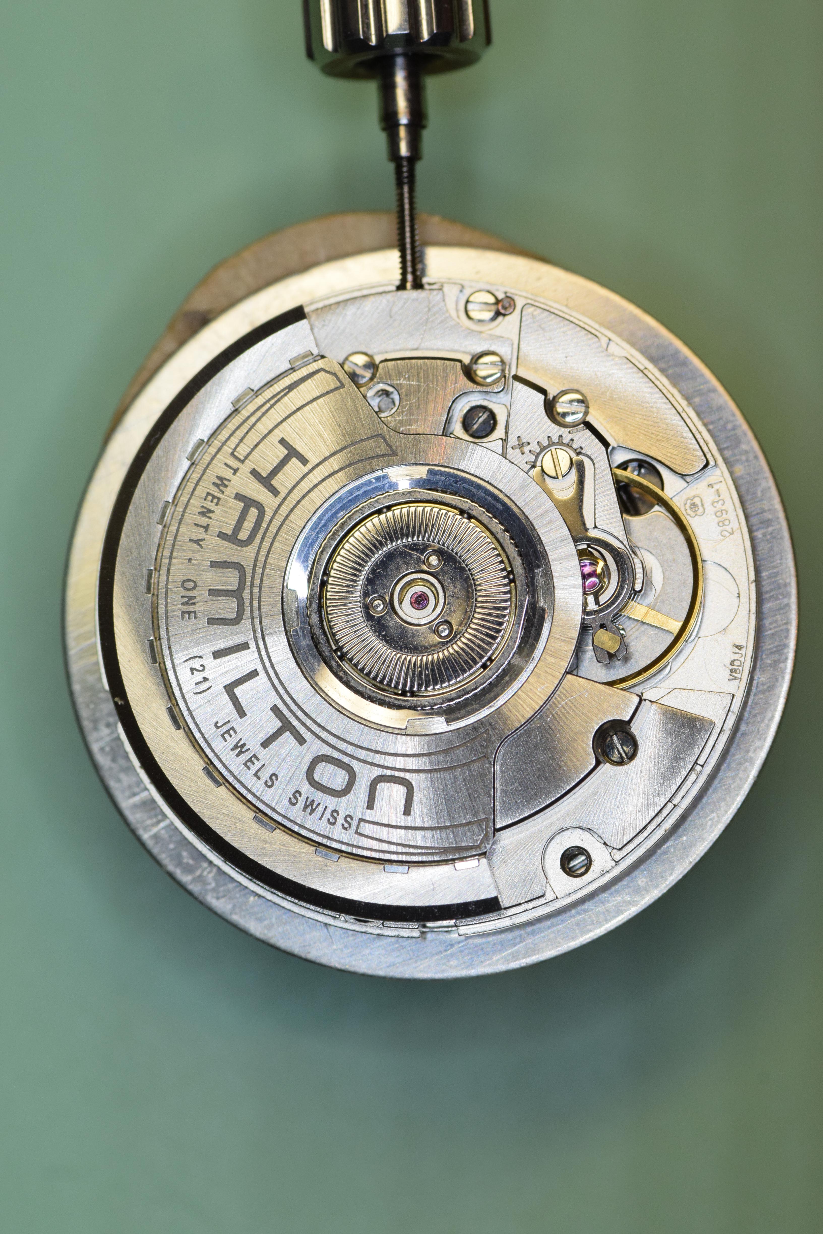
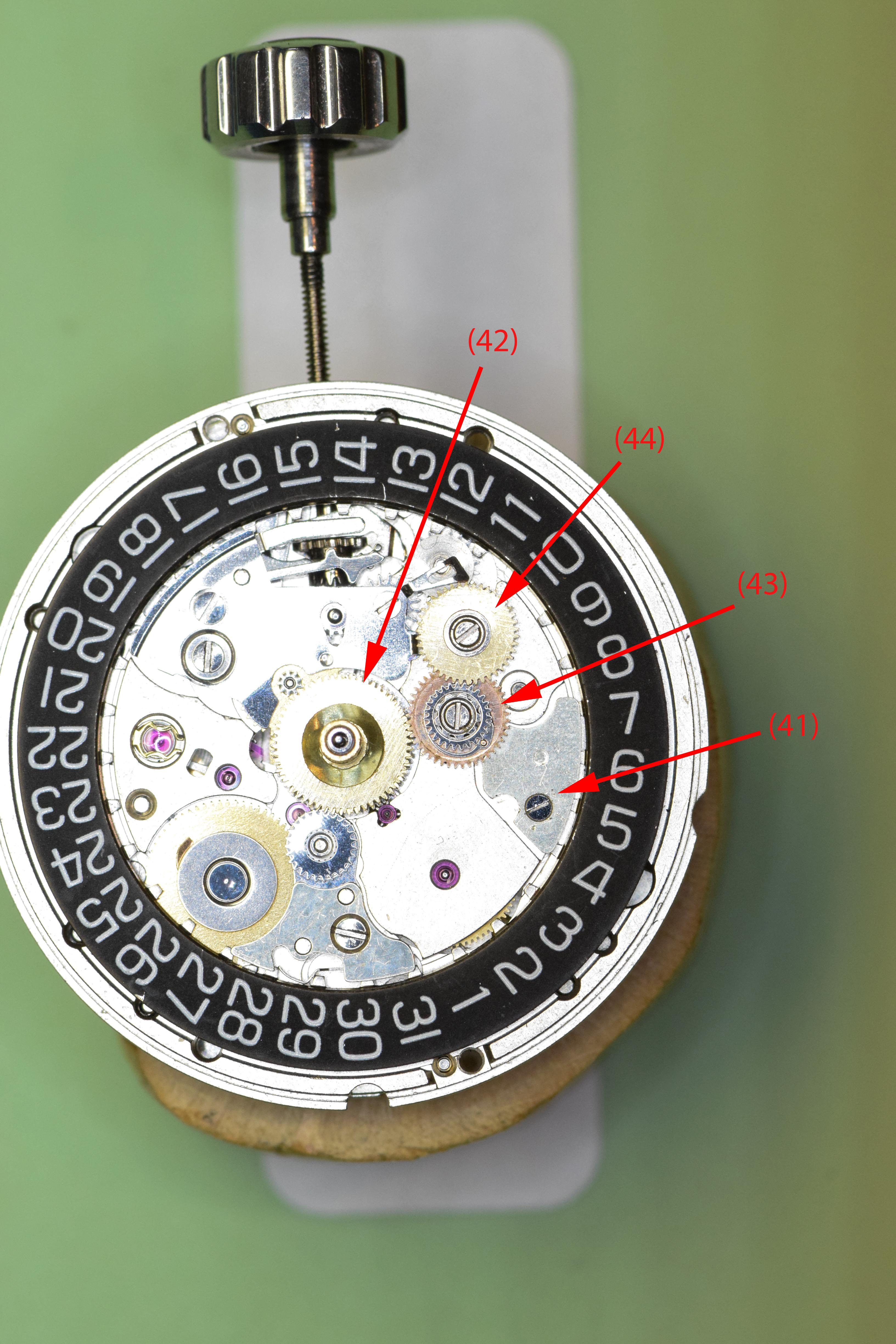
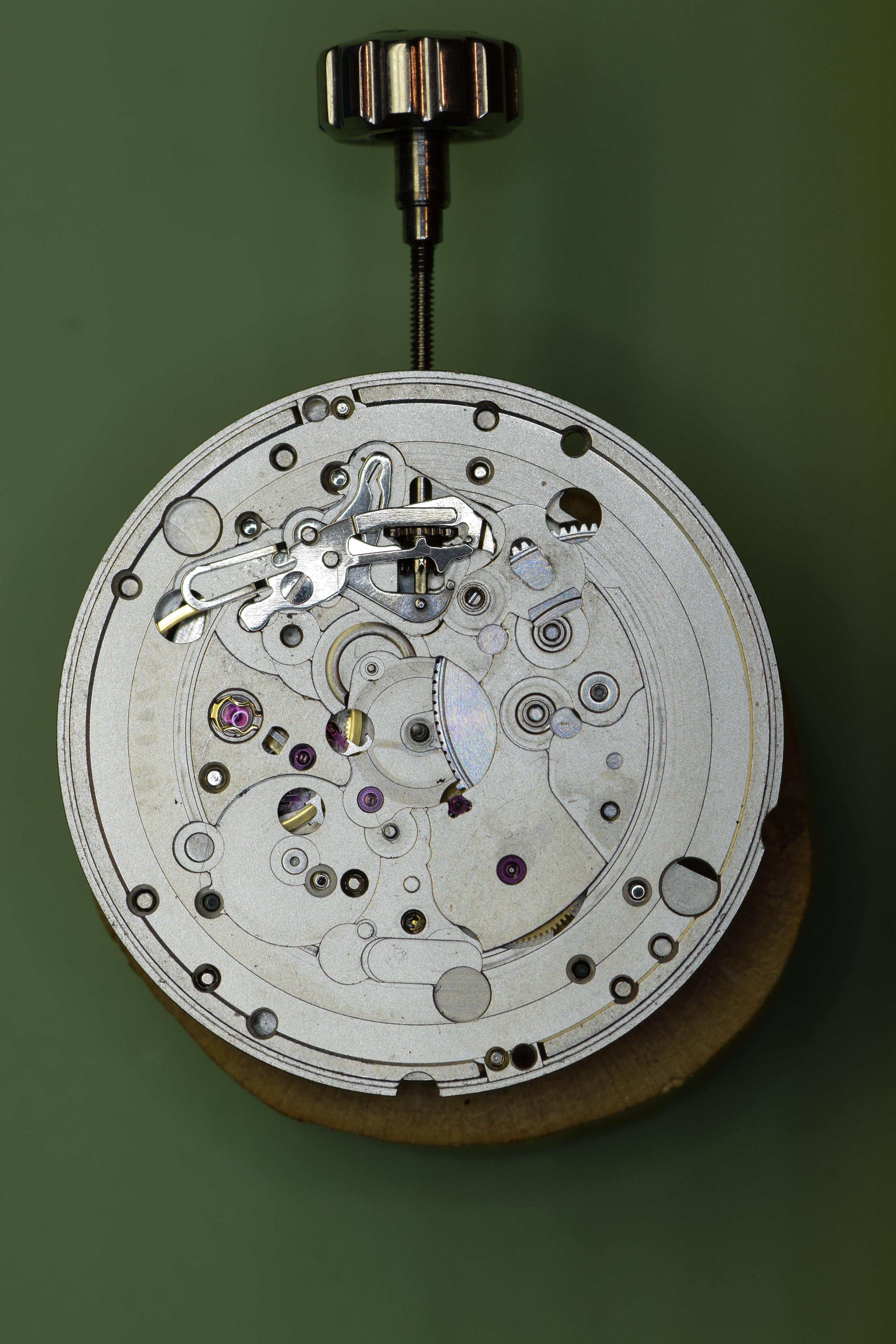
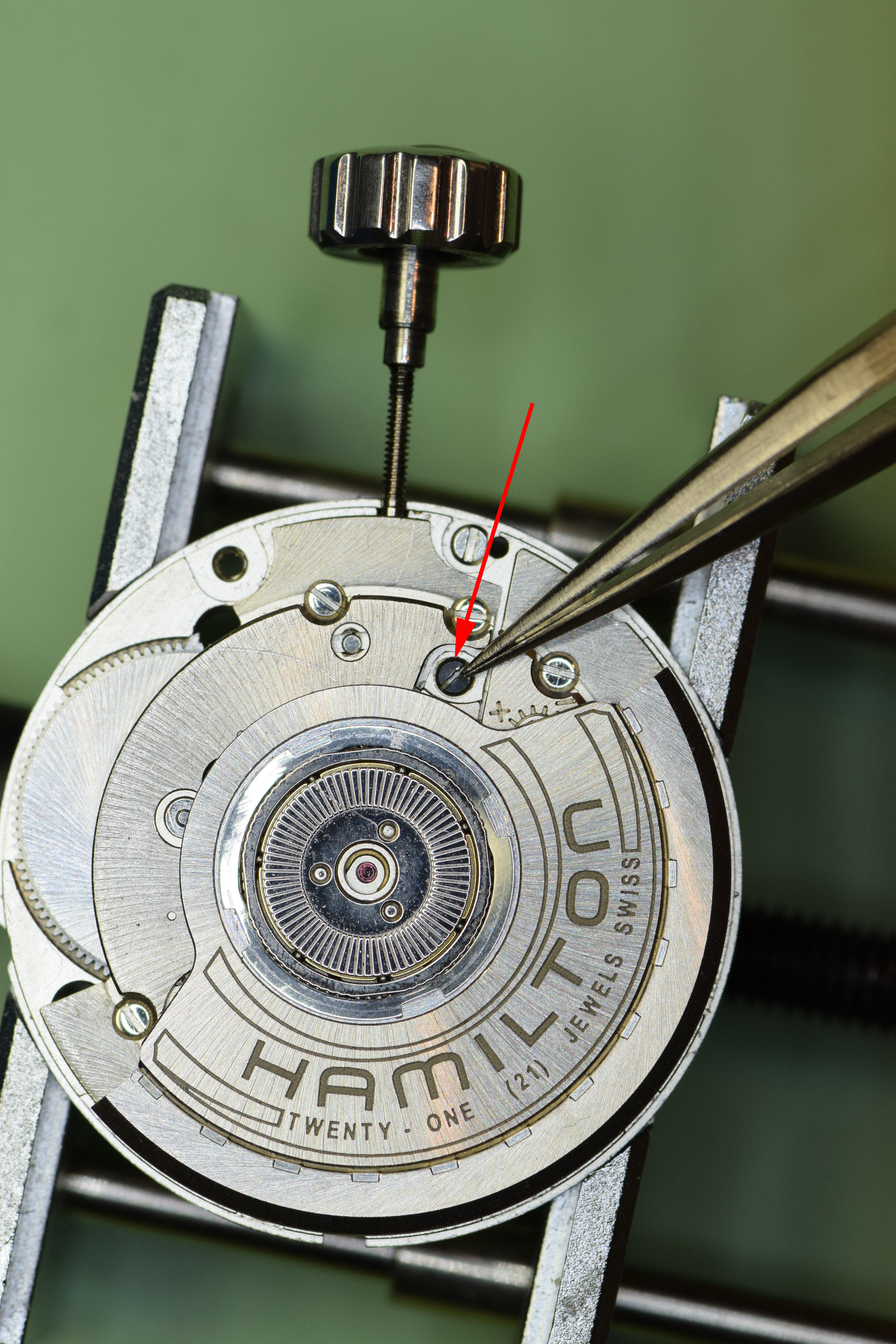
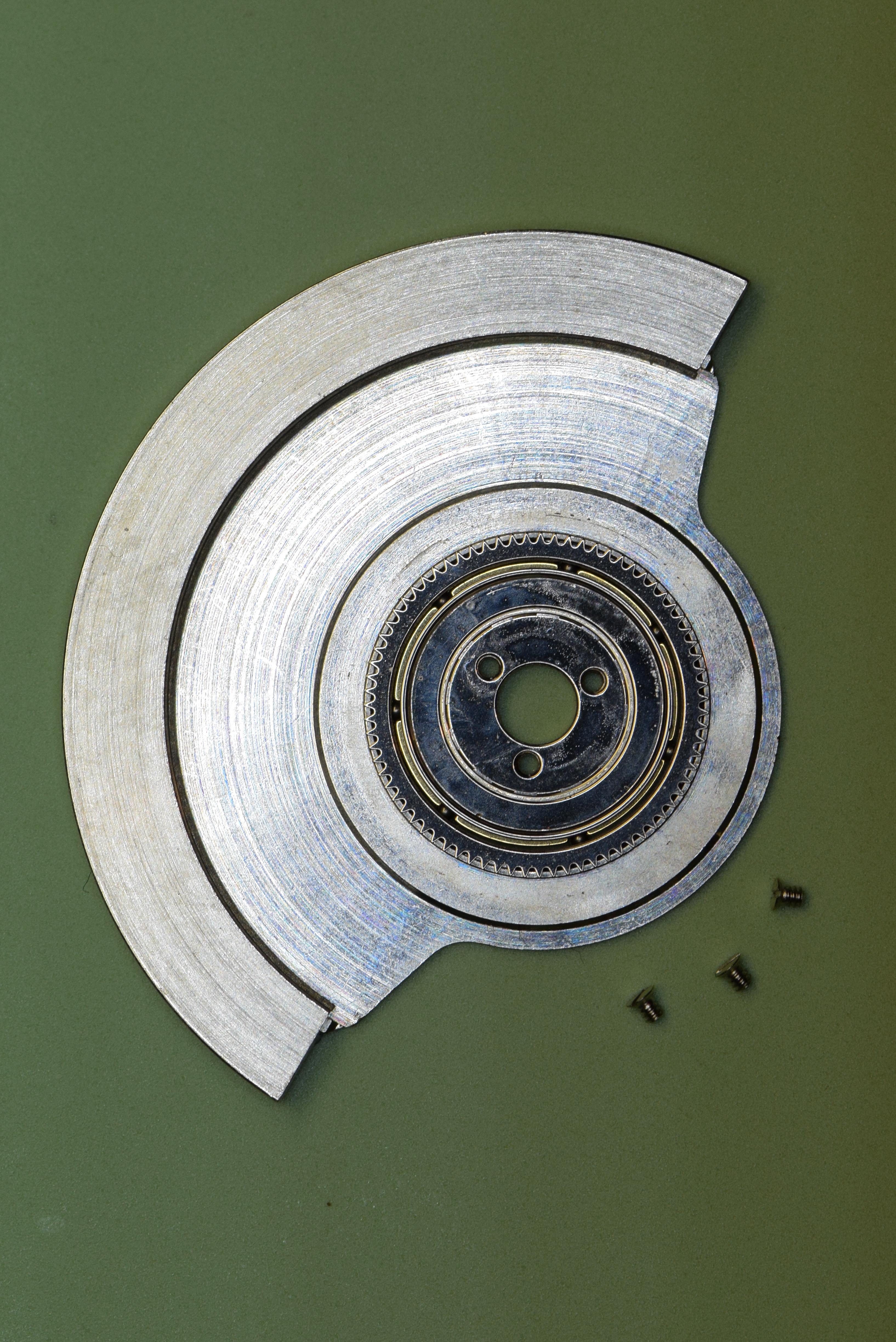
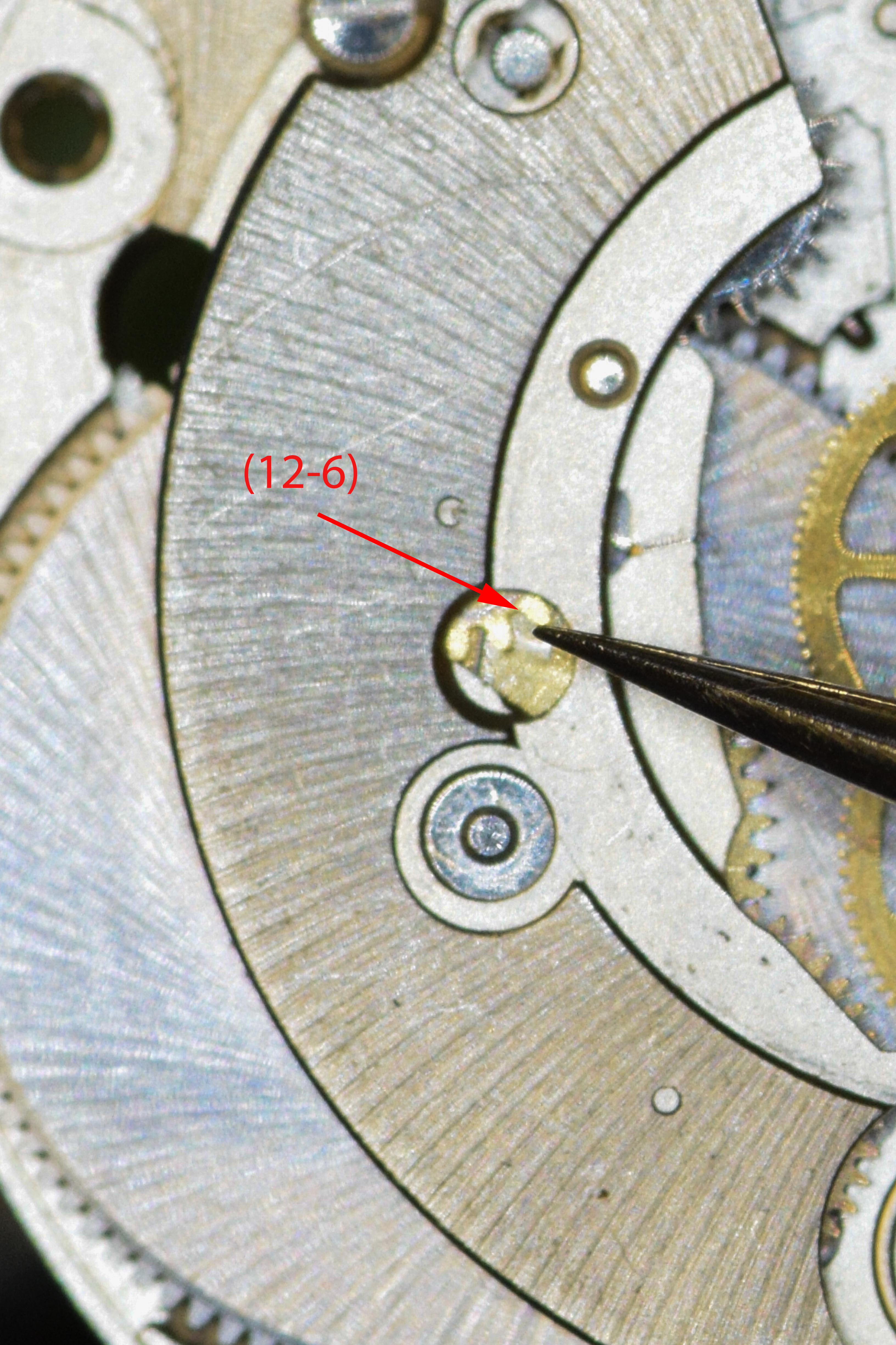
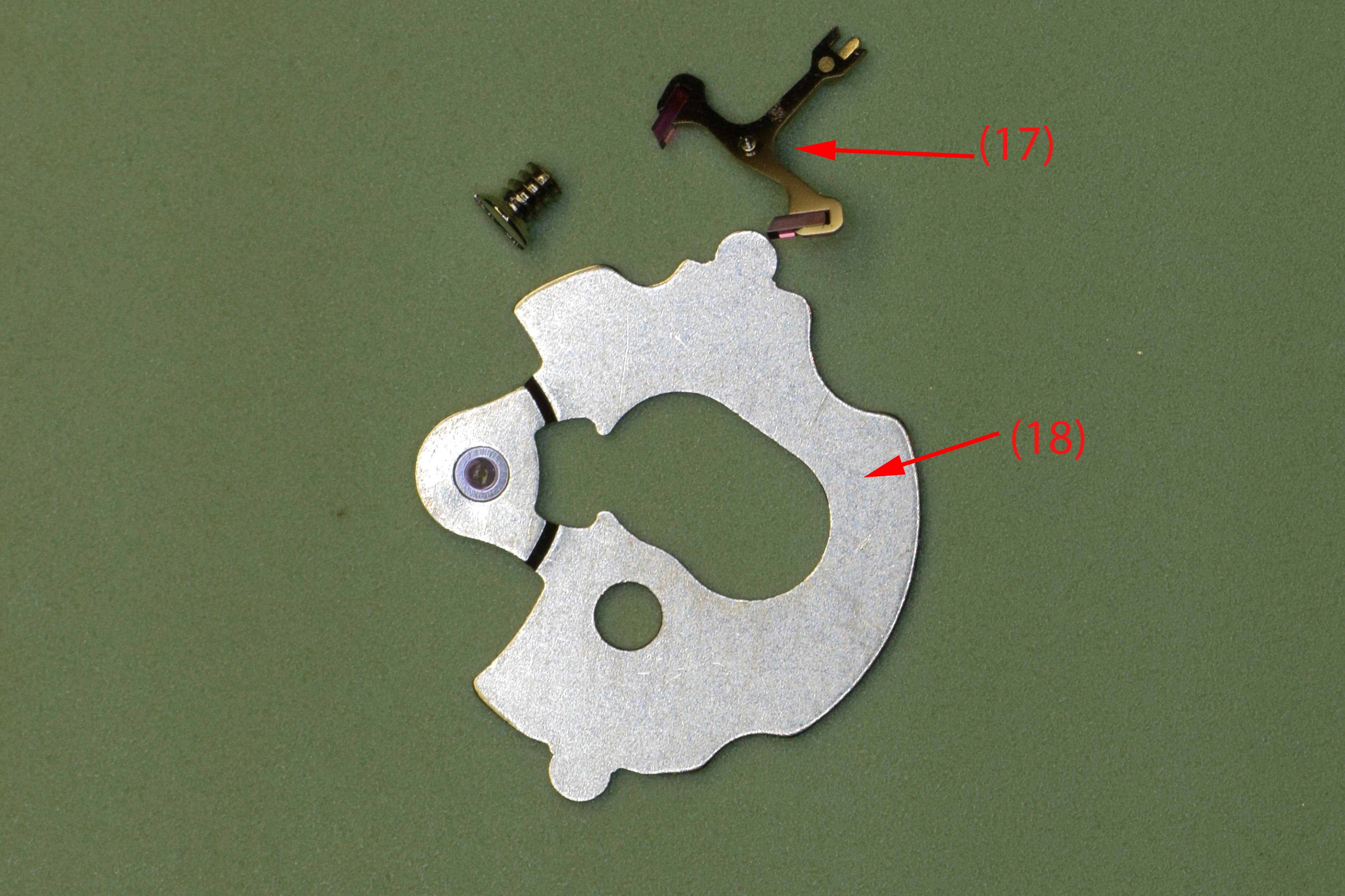
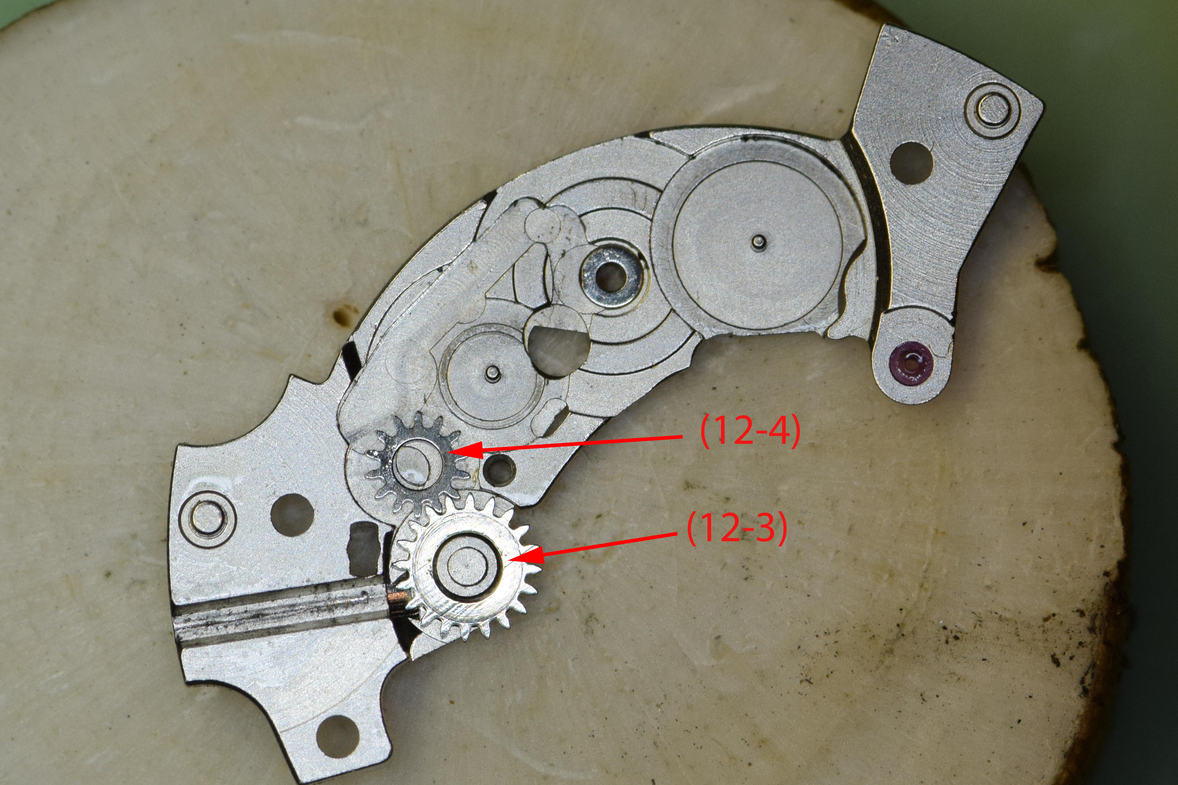
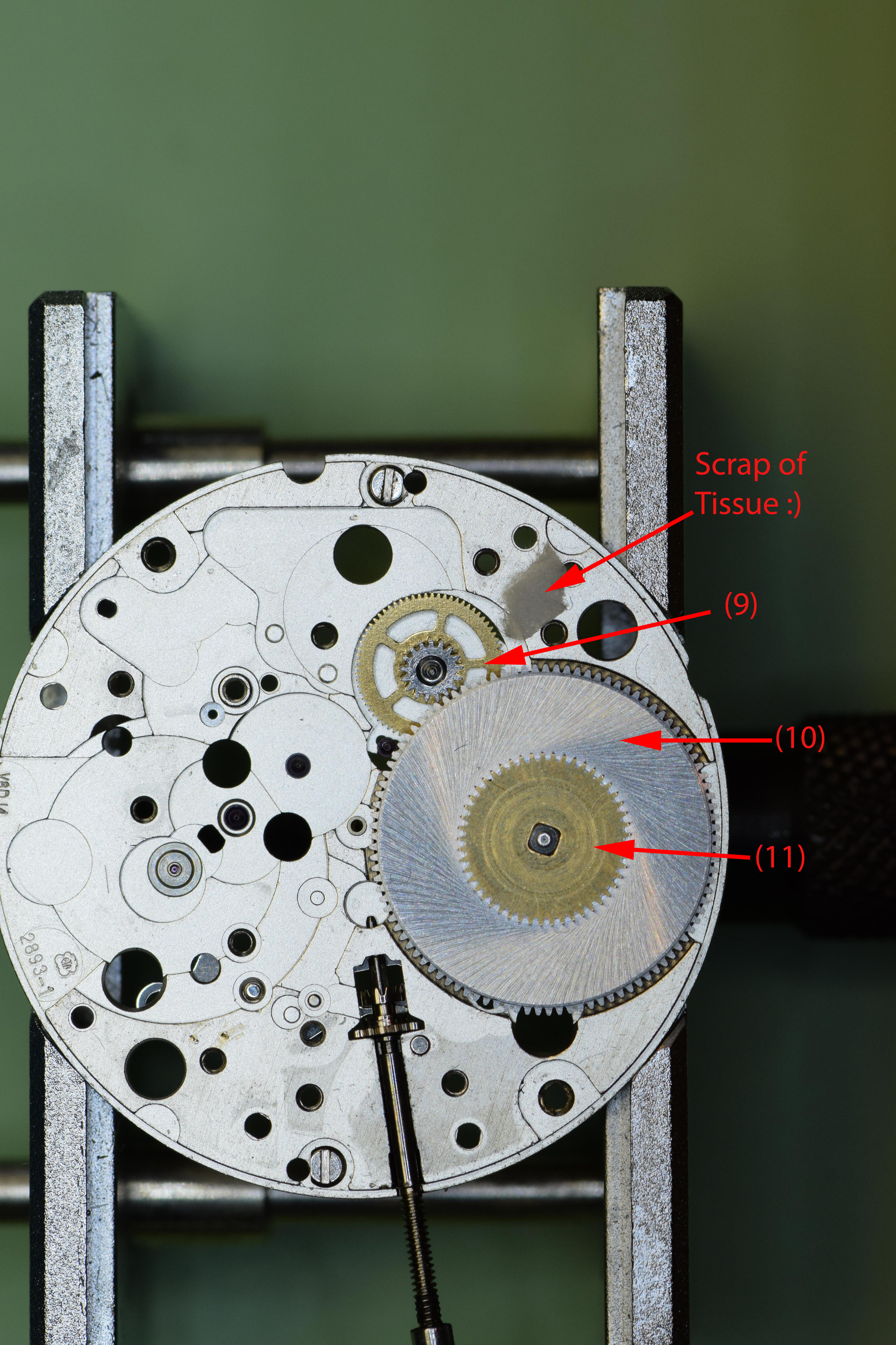
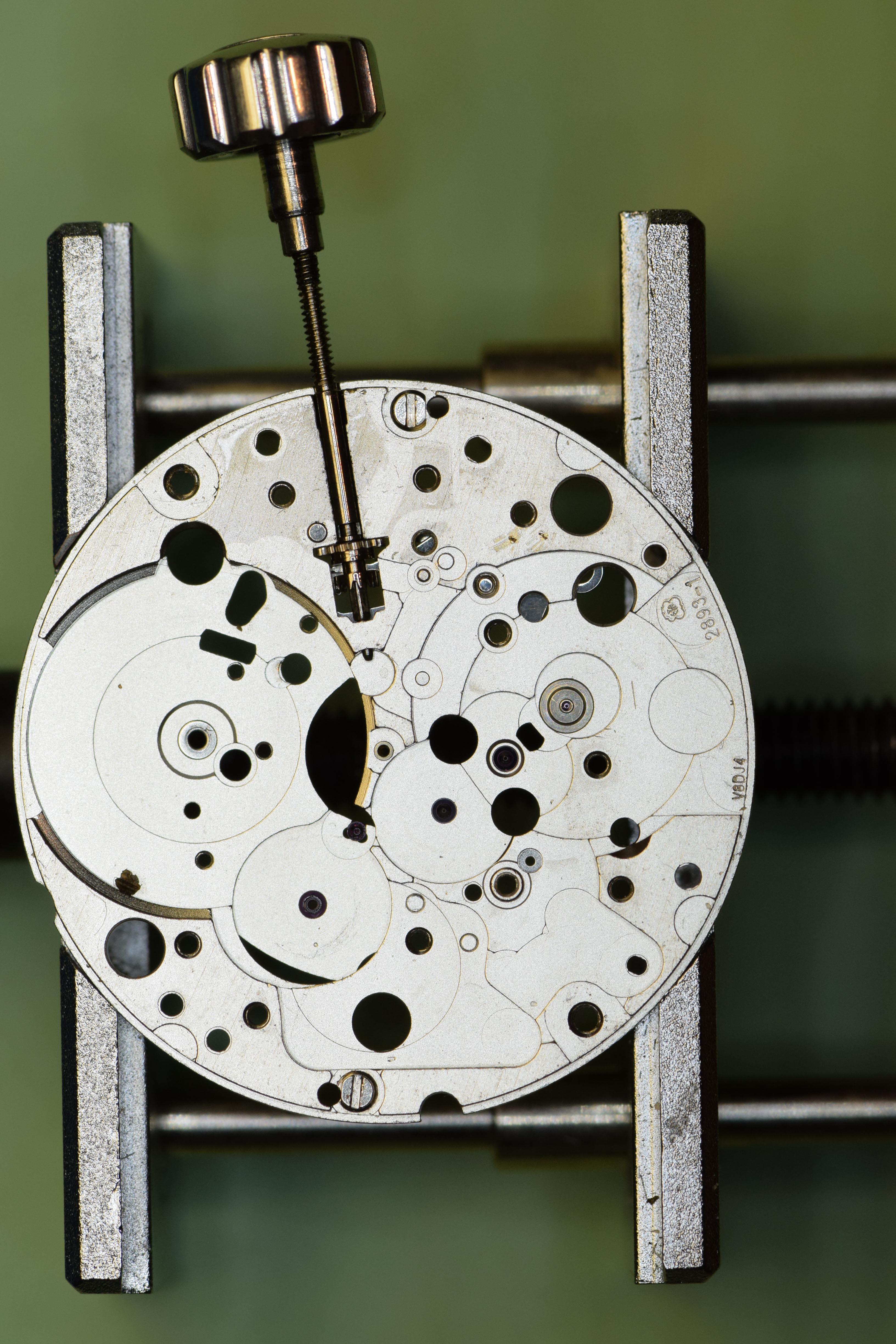
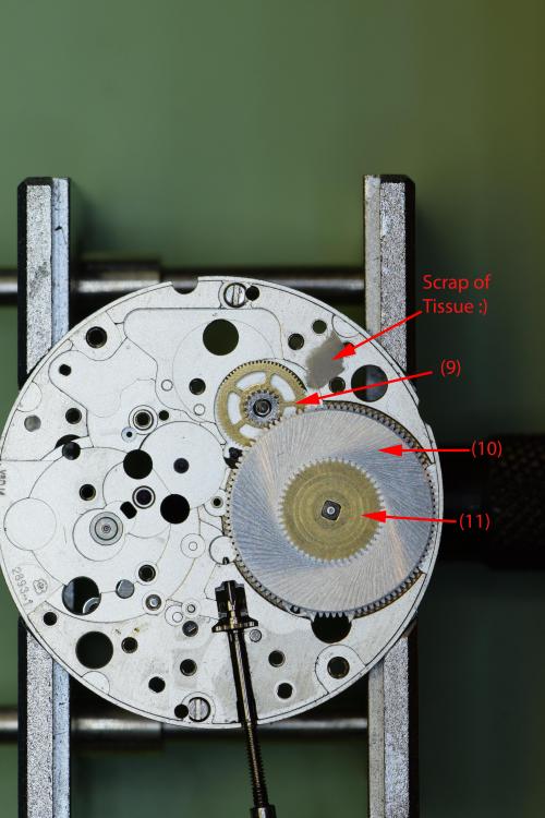
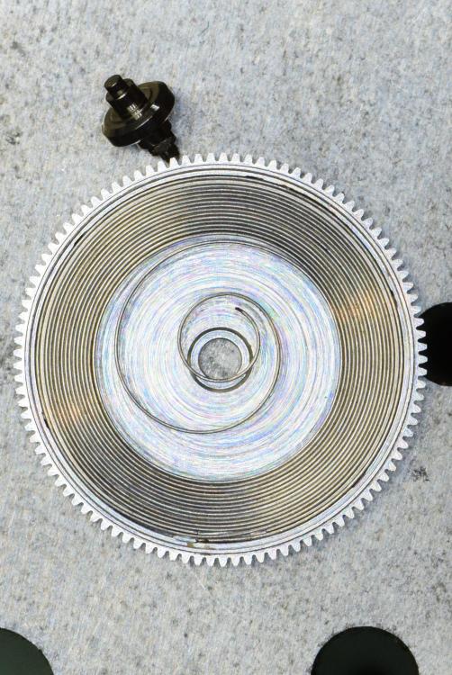
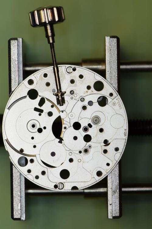
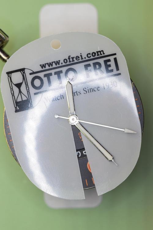
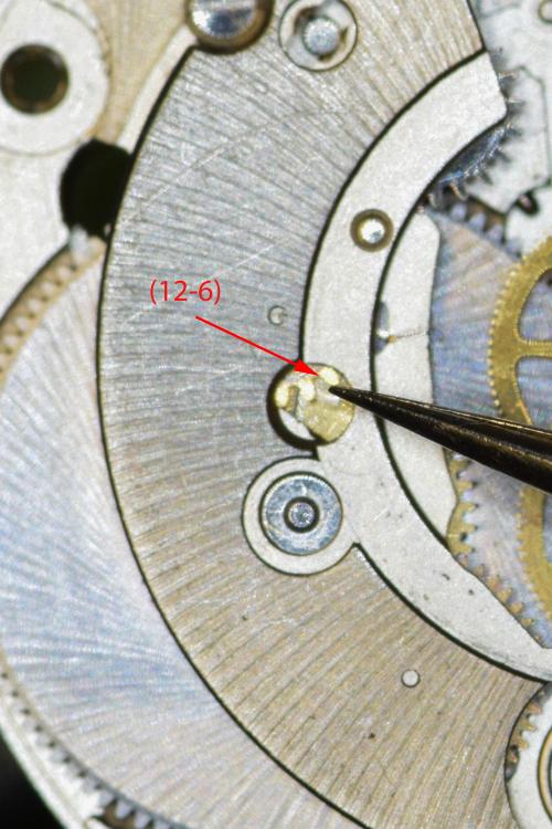
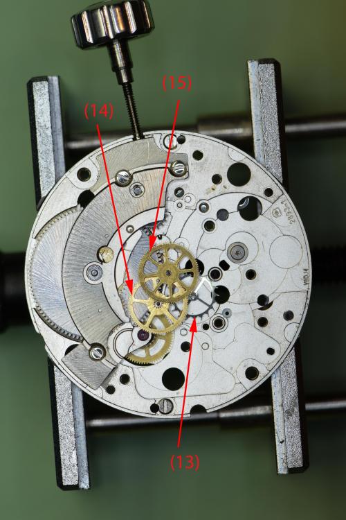
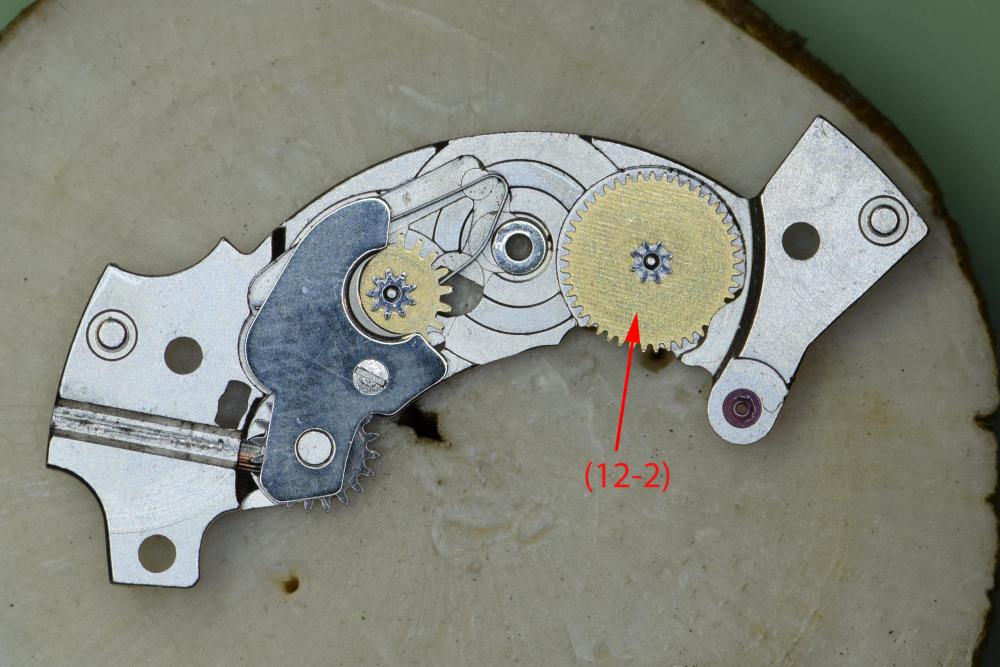
 Service Walk Through – ETA 2893-1 / Hamilton Khaki: Part 1 - Disassembly This is part 1 of my service of a Hamilton Khaki – dual time zone automatic based on the ETA 2893-1 movement. I purchased the watch on eBay and it runs for a short time then stops. Looks like it could use a good cleaning. Note that the part numbers in the images and text are consistent with those found in the ETA technical document for this movement. Disassembly of this movement is quite straightforward. The only "special" tool you need would be an oscillating weight bolt tool - and you only need this if you intend to remove the ball bearing assembly from the oscillating weight, which really isn't required. In this tear down I do use the tool - only because I recently acquired it and wanted to see how it worked Off we go.... The dial shows evidence of some sloppy workmanship in the watch's past – several scratches from prior hand removal. Here you see the back of the 2893-1 with its automatic rotor - nicely signed Hamilton. Preparing to remove the hands – with a safety sheet in place. After removing the dial, remove the dial support ring. This ring keeps the dial the proper distance from the second timezone disc. Without it, the disc will rub against the dial. Remove the second timezone disc from the center. This is a bit tricky as there’s no obvious place to grip it. I used two very small screwdrivers on each side to lift the indicator straight up. Be careful not to scratch it! Disc removed. Note the following parts: Hour Wheel (42); Hour Indicator Driving Wheel (43); Corrector Setting Wheel (44); Additional Indicator Maintaining Plate (41) Pop off the dial washer – note that you cannot simply lift the hour wheel (42) off at this point. It is held in place by the hour indicator driving wheel (43). I remove the hour indicator driving wheel (43) followed by the corrector setting wheel (44). The hour wheel (42) is now simply lifted off, followed by the additional indicator maintaining plate (41). Next components to remove are the Date Indicator Maintaining Plate (40) and the Minute Train Bridge (35). We move on to remove the Intermediate Date Wheel (39). The Date Jumper (38) has also been exposed when we removed the maintaining plate, so we remove it. Finally, we remove the Date Indicator (37) and the Date Indicator Driving Wheel (36). Now on to some of the motion and keyless work. We remove the Minute Wheel (34), Cannon Pinion with Driving Wheel (33), Double Corrector (32) and Date Corrector Intermediate Setting Wheel (31). Before dealing with the rest of the keyless work, we flip the movement over and remove the automatic work. After removing the 3 blue screws we lift the entire unit up gently by the Oscillating Weight (28). With the automatic work out of the way – I notice that the Stop Lever (Hack) is missing! Will try and source one. Back to the automatic work. Removing these 3 screws will allow the oscillating weight to come off the Automatic Framework (21) and its components. Using the appropriate Bolt tool (pictured with the red handle) – I remove the Oscillating Weight Bolt (28-3) and free the Ball Bearing (28-2) from the Oscillating Weight (28-1). There was no compelling reason to disassemble this portion of the movement. With the Oscillating Weight out of the way, remove the Auxiliary Reverser (27). Flip the unit over once again and remove the screw and Automatic Device Lower Bridge (26). Remove the Reverser (25), Reverser Wheel (24), Reduction Wheel (23) and Intermediate Reduction Wheel (22). A view of the underside of these components Remove the single screw and gently lift off the Balance Assembly (20) with the Balance Complete (19). Carefully let the power down by releasing the Click (12-6) and slowly letting the crown wind down. Remove the Pallet Bridge (18) and Pallets (17). Remove the Train Wheel Bridge (16). Remove the Fourth Wheel (15), Third Wheel (14) and Escape Wheel (13). Remove the 3 screws and the Barrel Bridge (12) Flip the bridge over and lift off the Ratchet Wheel Driving Wheel (12-2) Remove the screw and the Click Plate (12-7), followed by the Click (12-6), Intermediate Ratchet Wheel (12-5), Intermediate Crown Wheel (12-4) and Crown Wheel (12-3). Note that the Intermediate Crown Wheel is under the Click Plate. When I removed the plate, the wheel was stuck to it due to some old oil. Here you can see the Intermediate Crown Wheel as it was stuck. This shows the proper placement of the wheels. Remove the Ratchet Wheel (11), the Mainspring Barrel (10) and Intermediate Wheel (9). Note the scrap of tissue that found its way onto the movement. I was so focused on taking pics that I didn’t notice J Pop the lid off the barrel. Remove the mainspring arbor And finally, remove the mainspring The movement side is now completely bare. Let’s flip it over and finish off the keyless work. Unscrew and remove the Setting Lever Jumper (8), Yoke (7) and the Setting Lever (6) Remove the Date Corrector Operating Lever (5), Winding Stem (4), Winding Pinion (3) and the Sliding Pinion (2) All stripped down Ready for the Ultrasonic!!! Hope you enjoyed this.


-
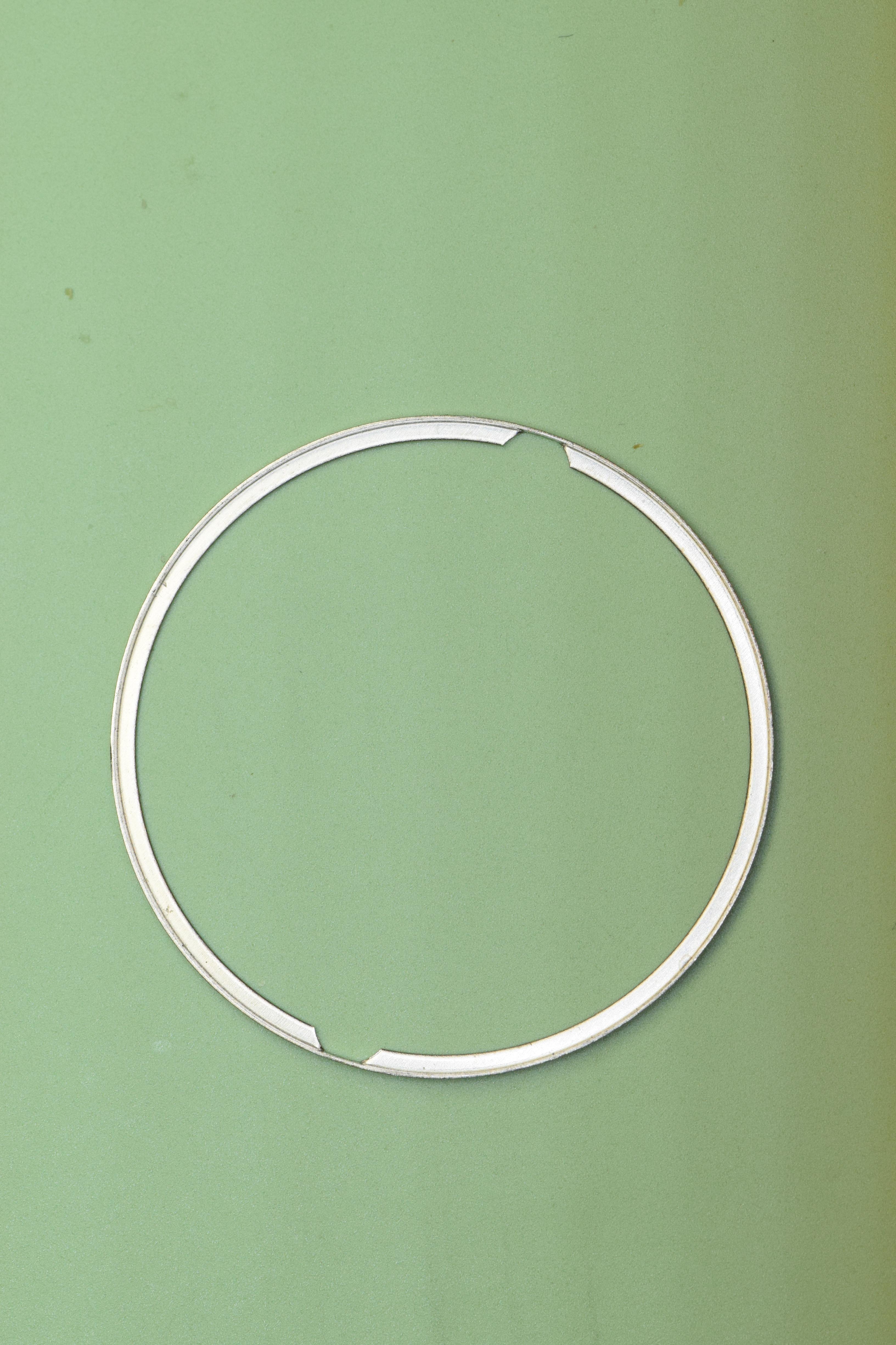
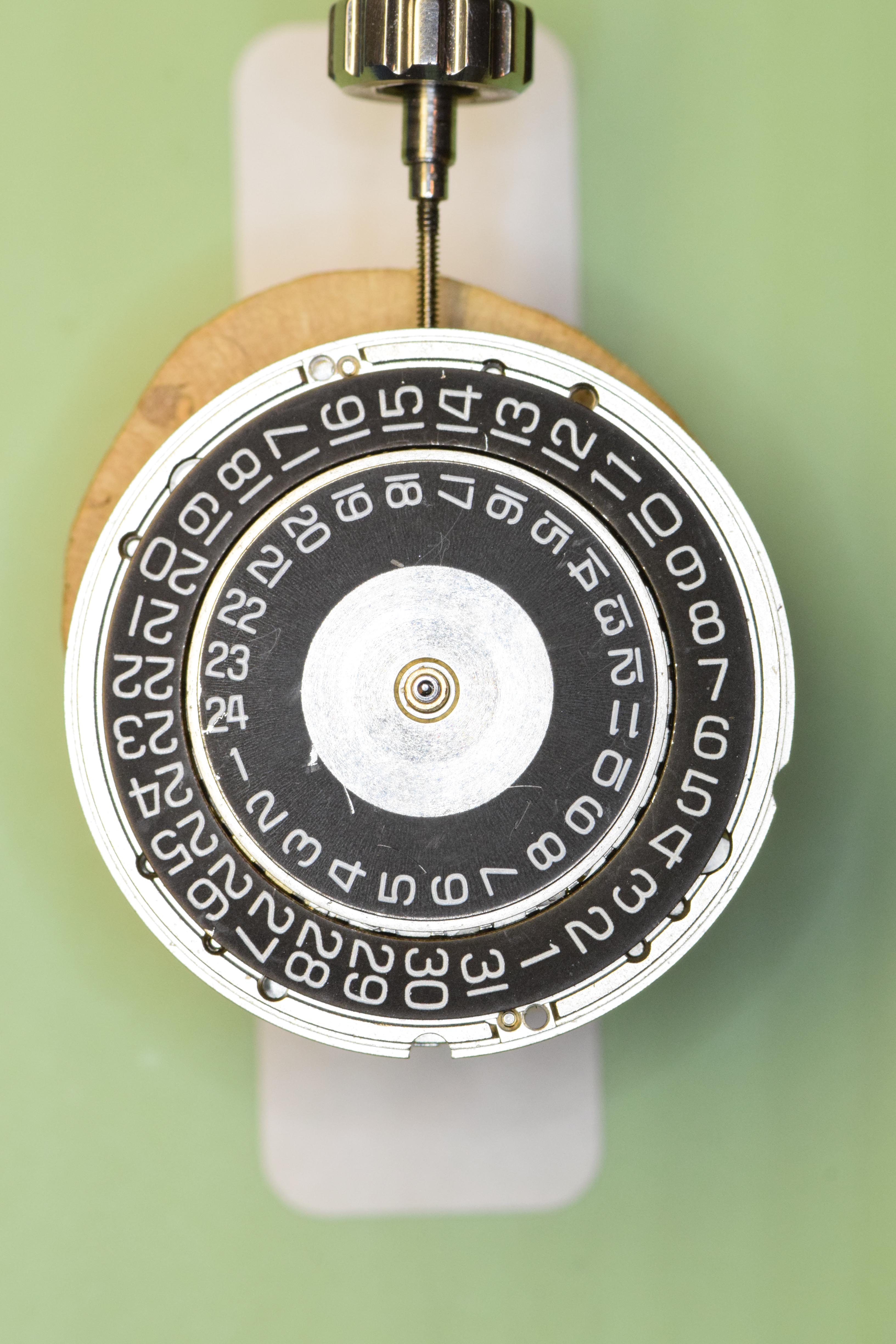
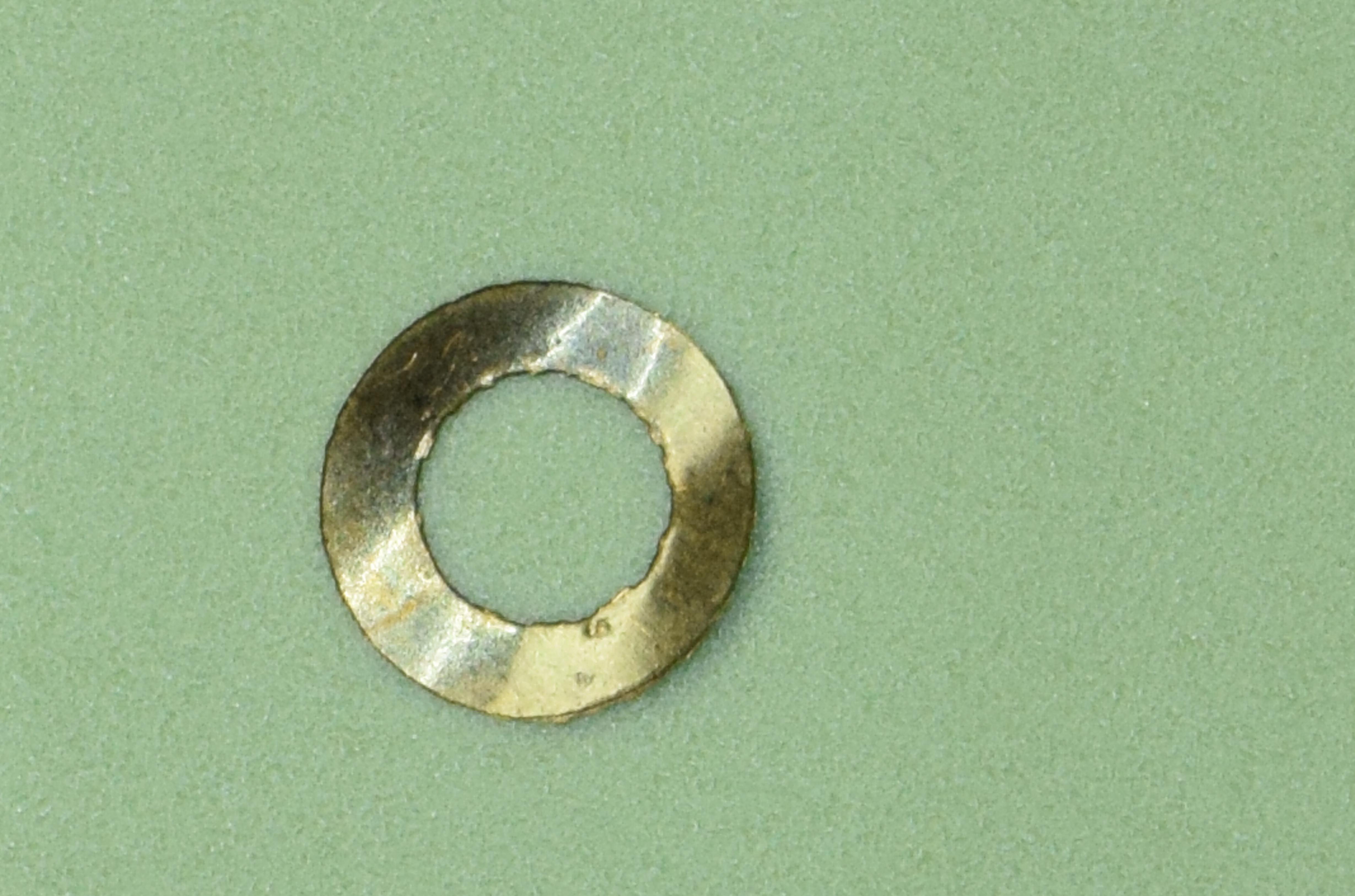
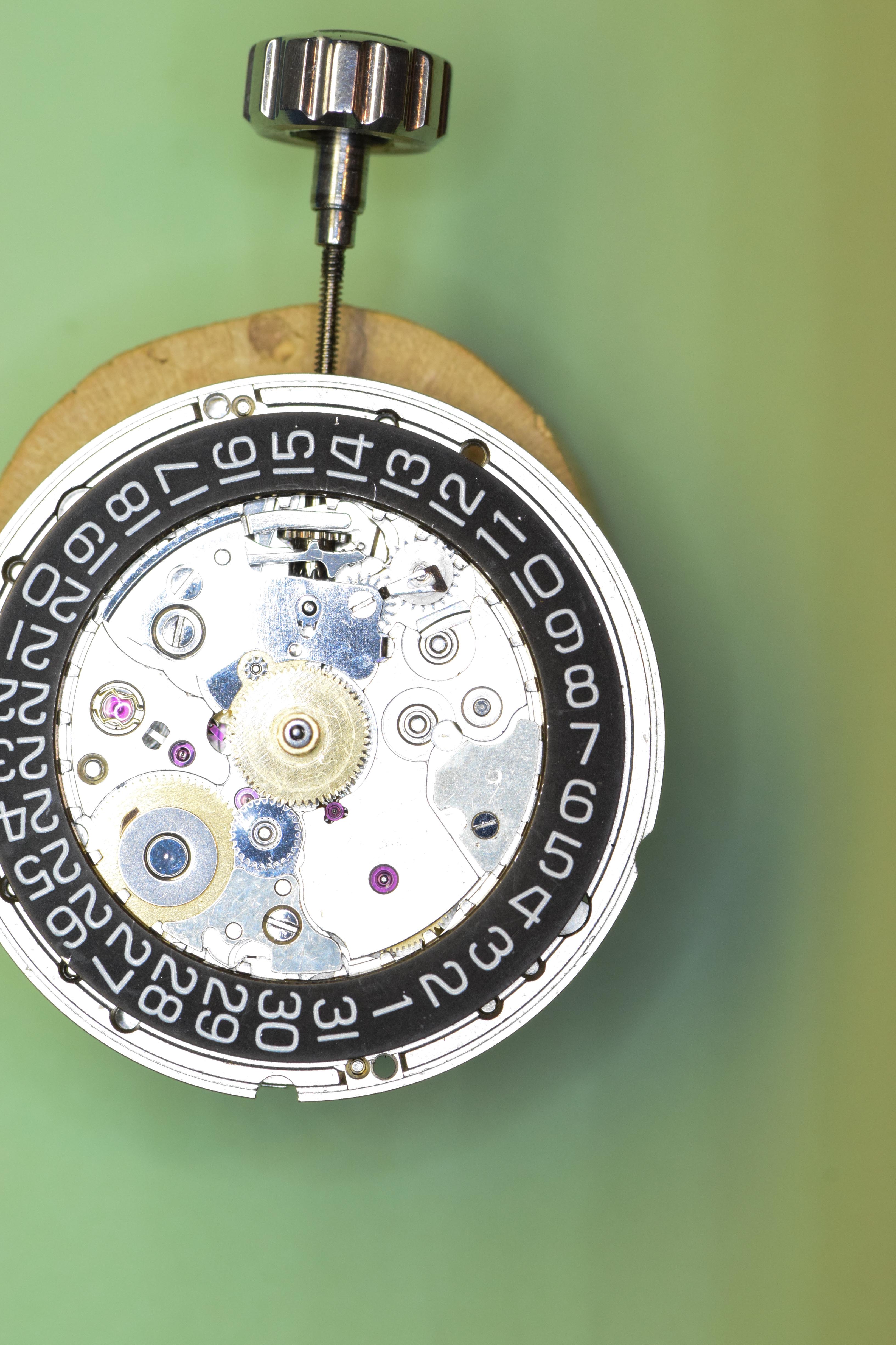
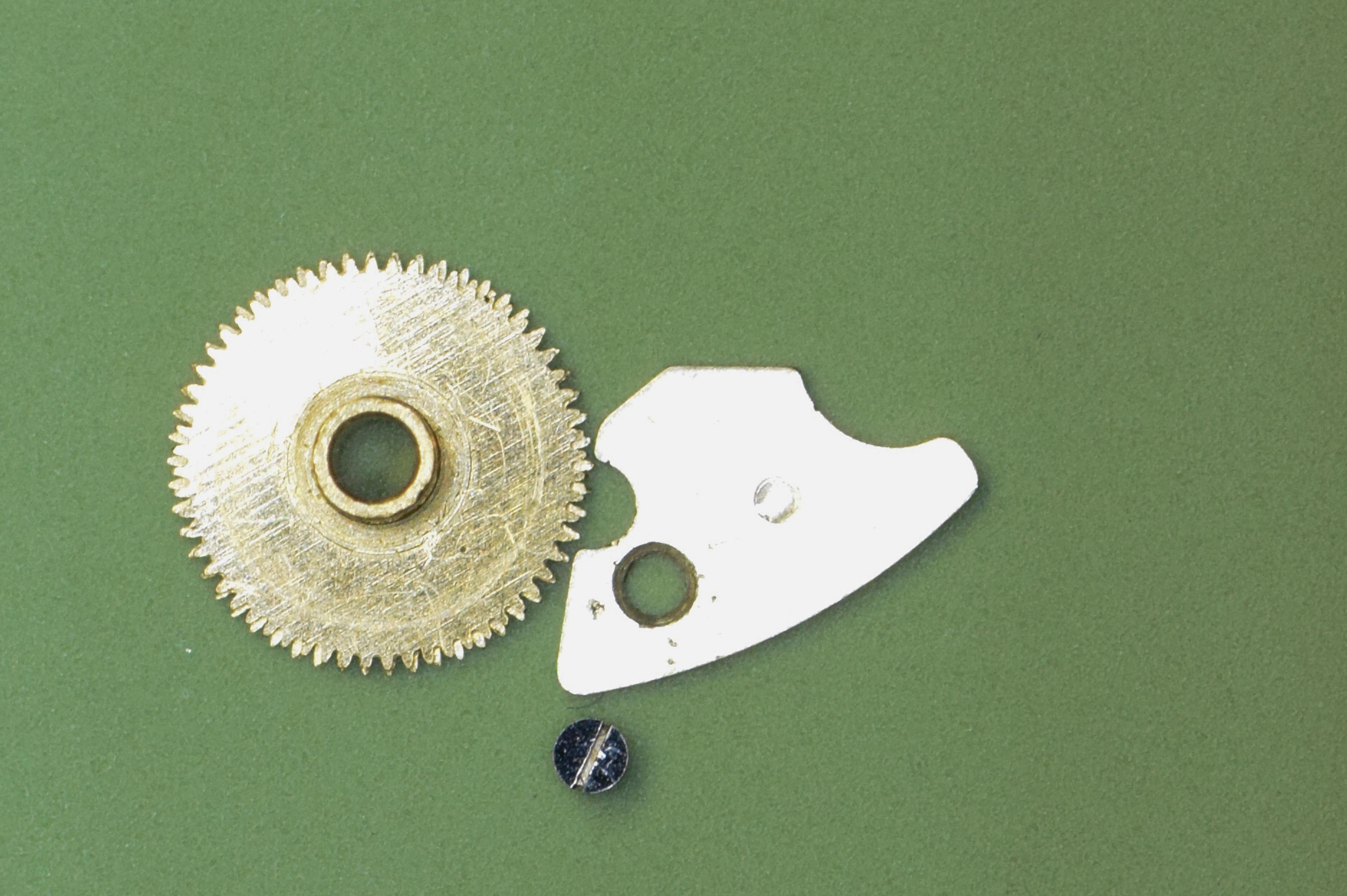
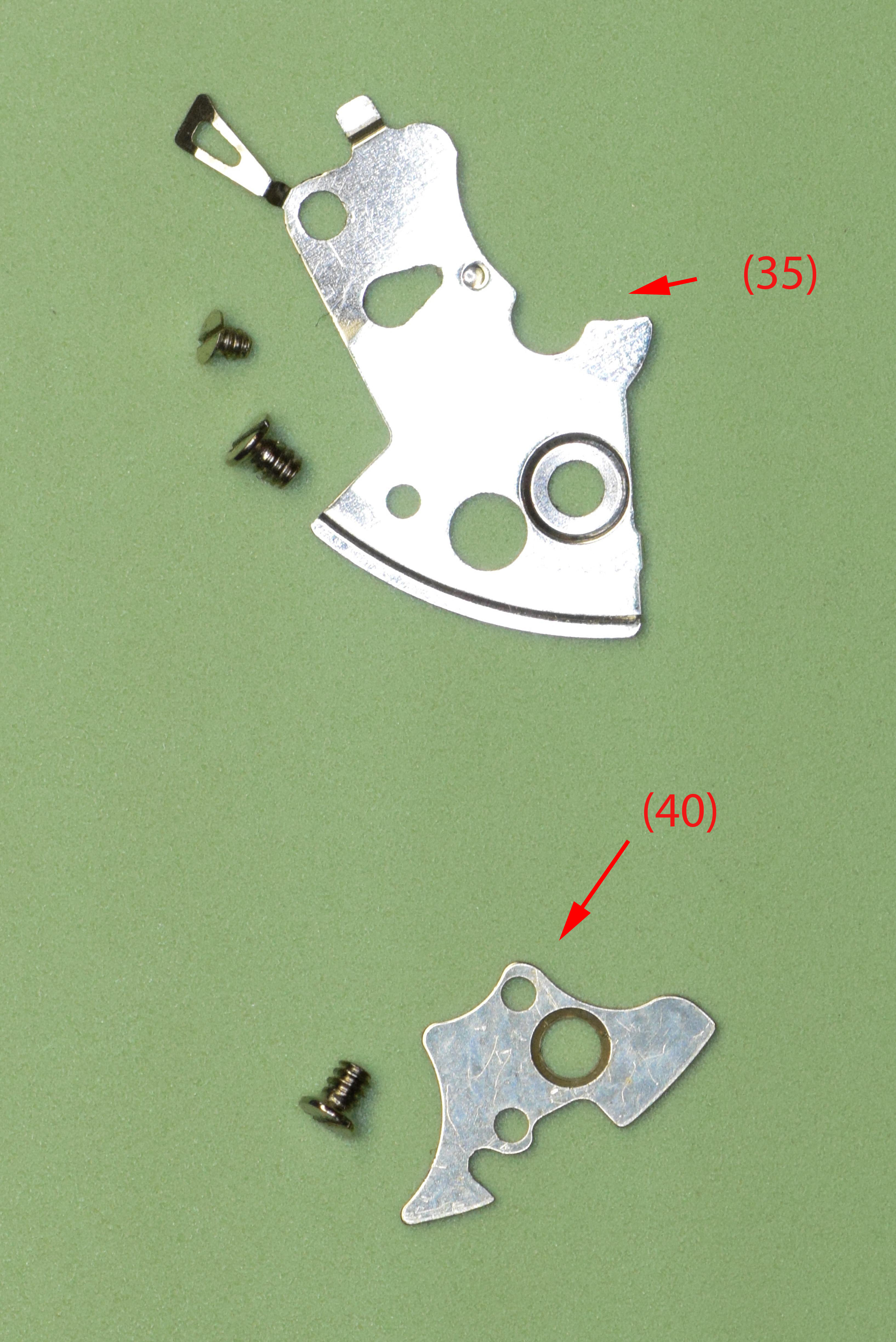
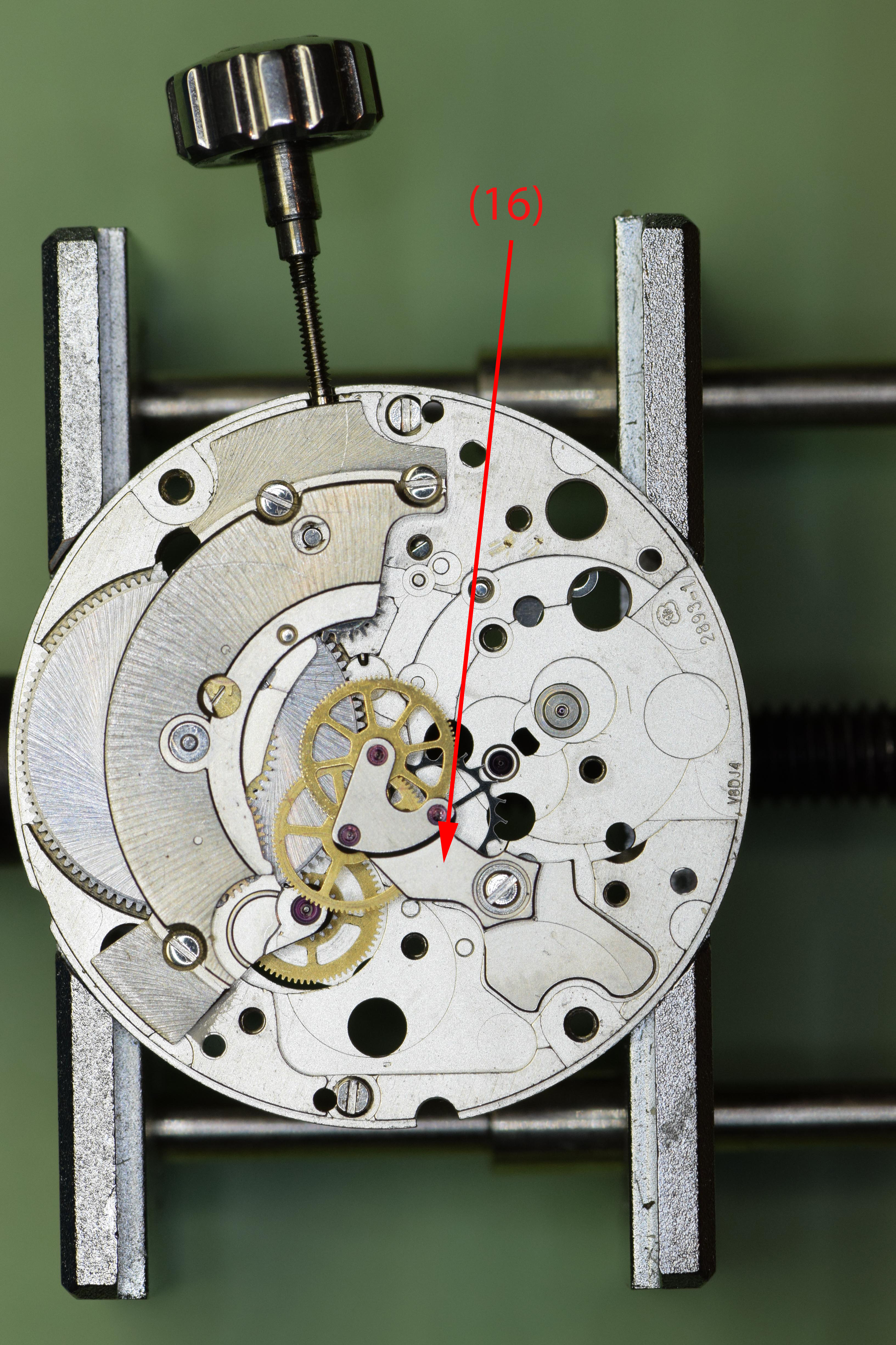
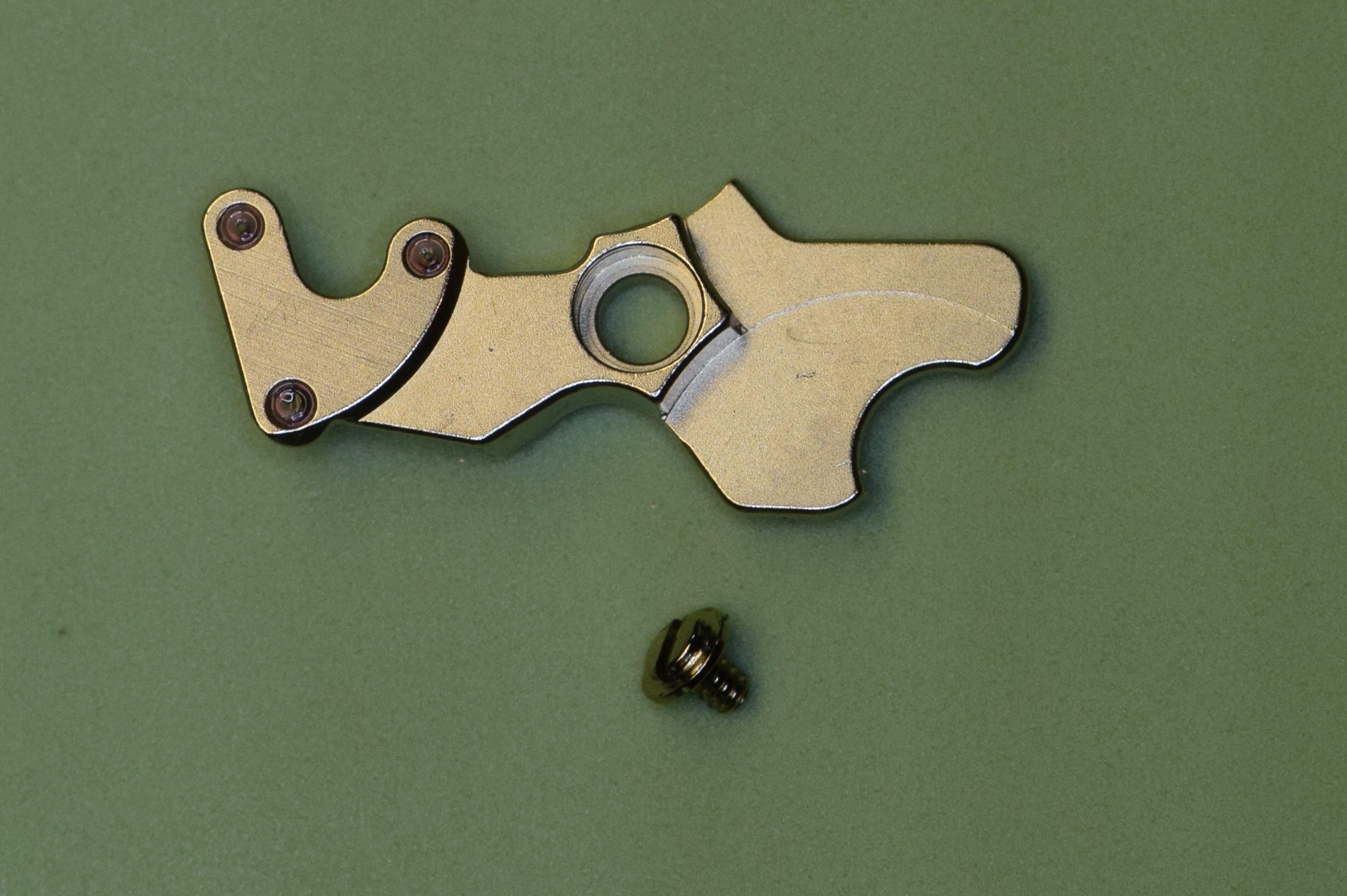
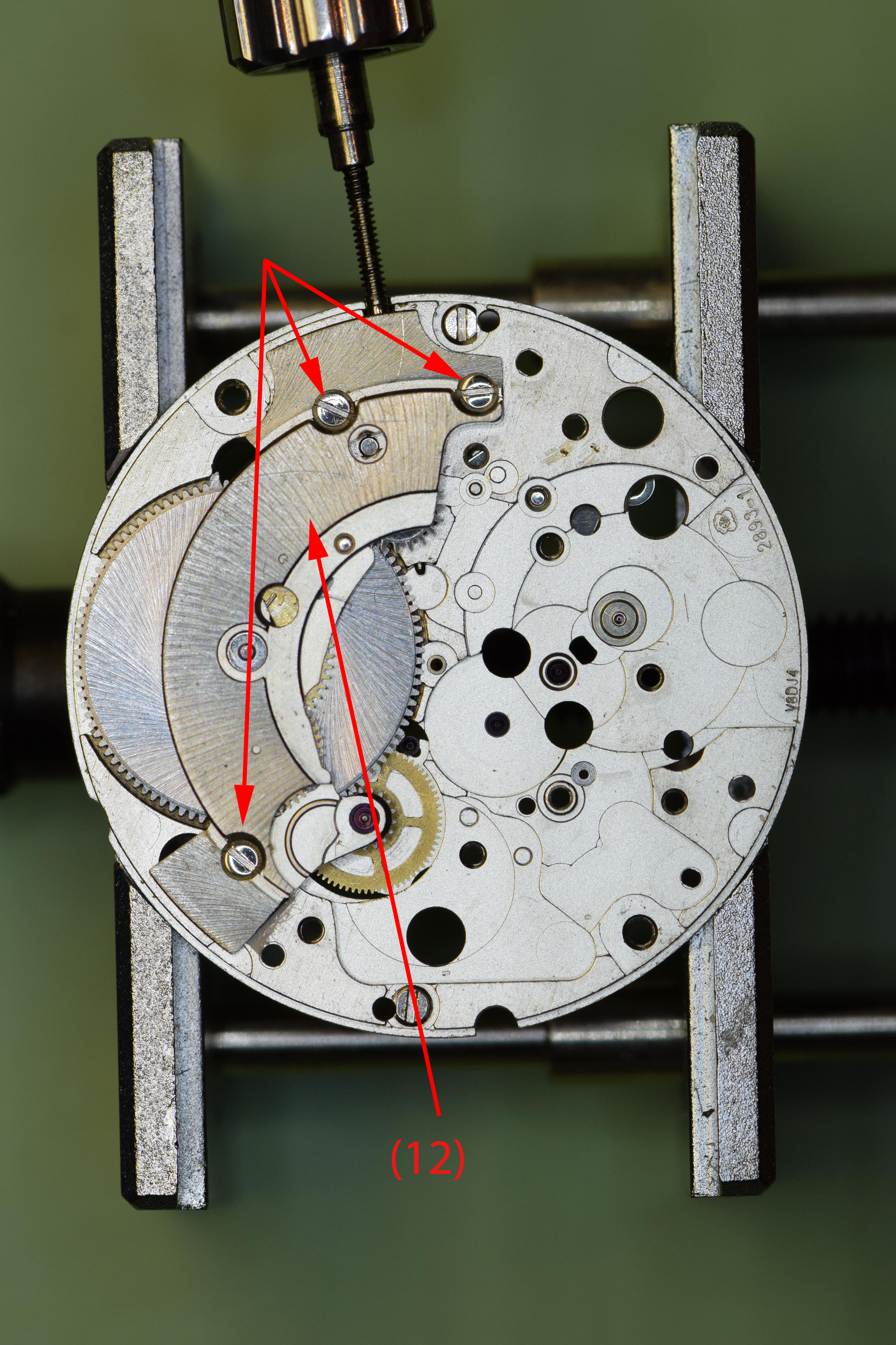
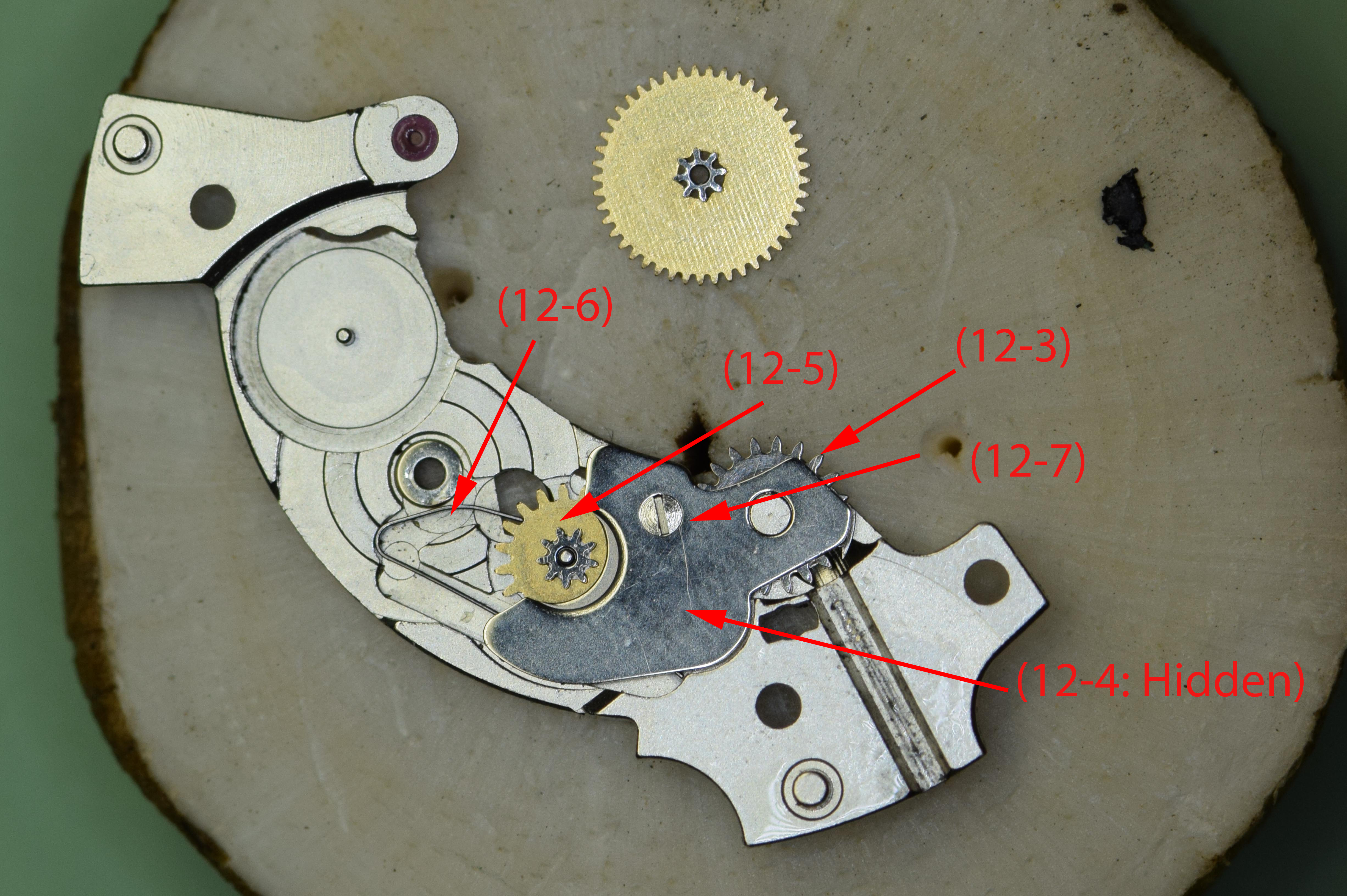
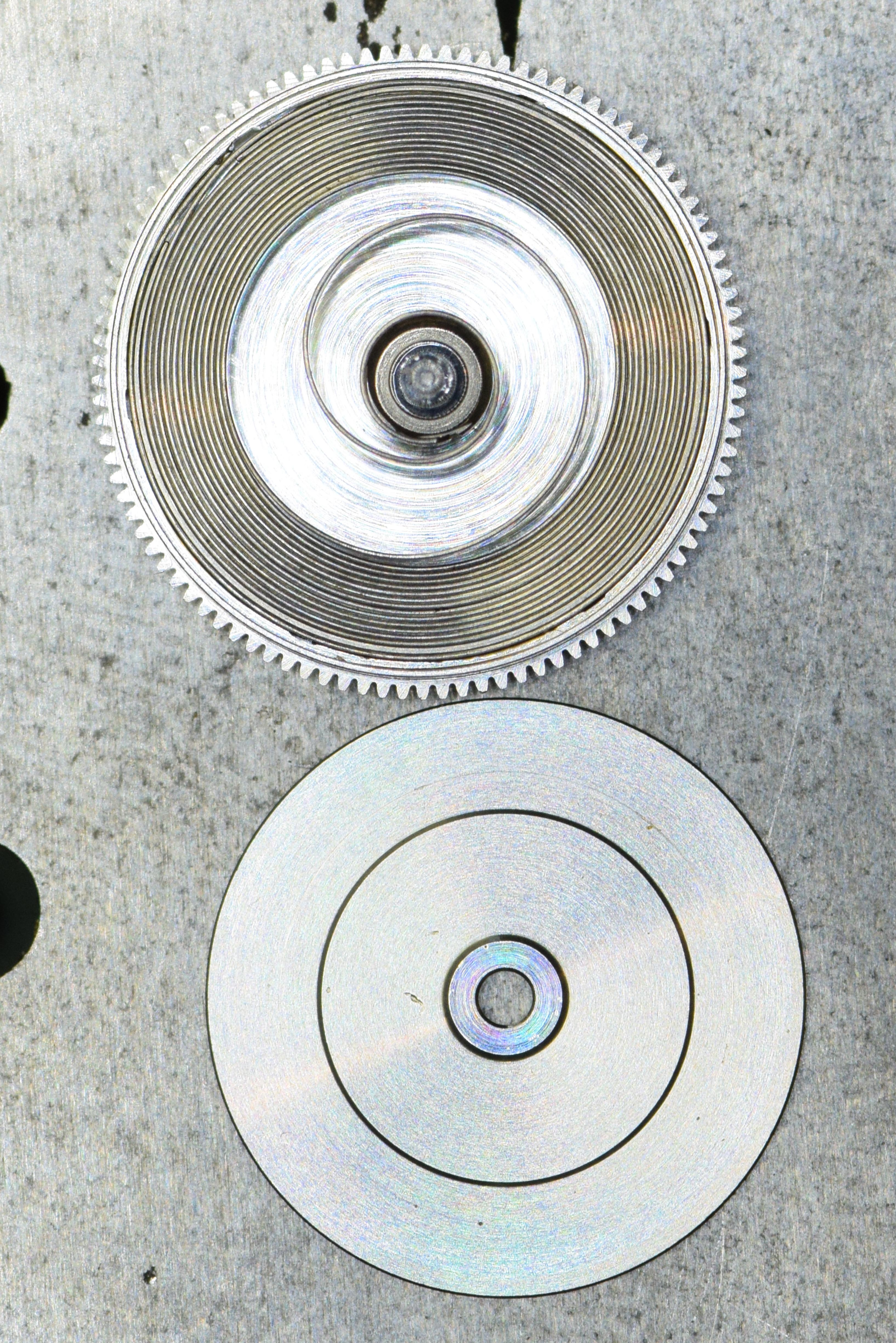
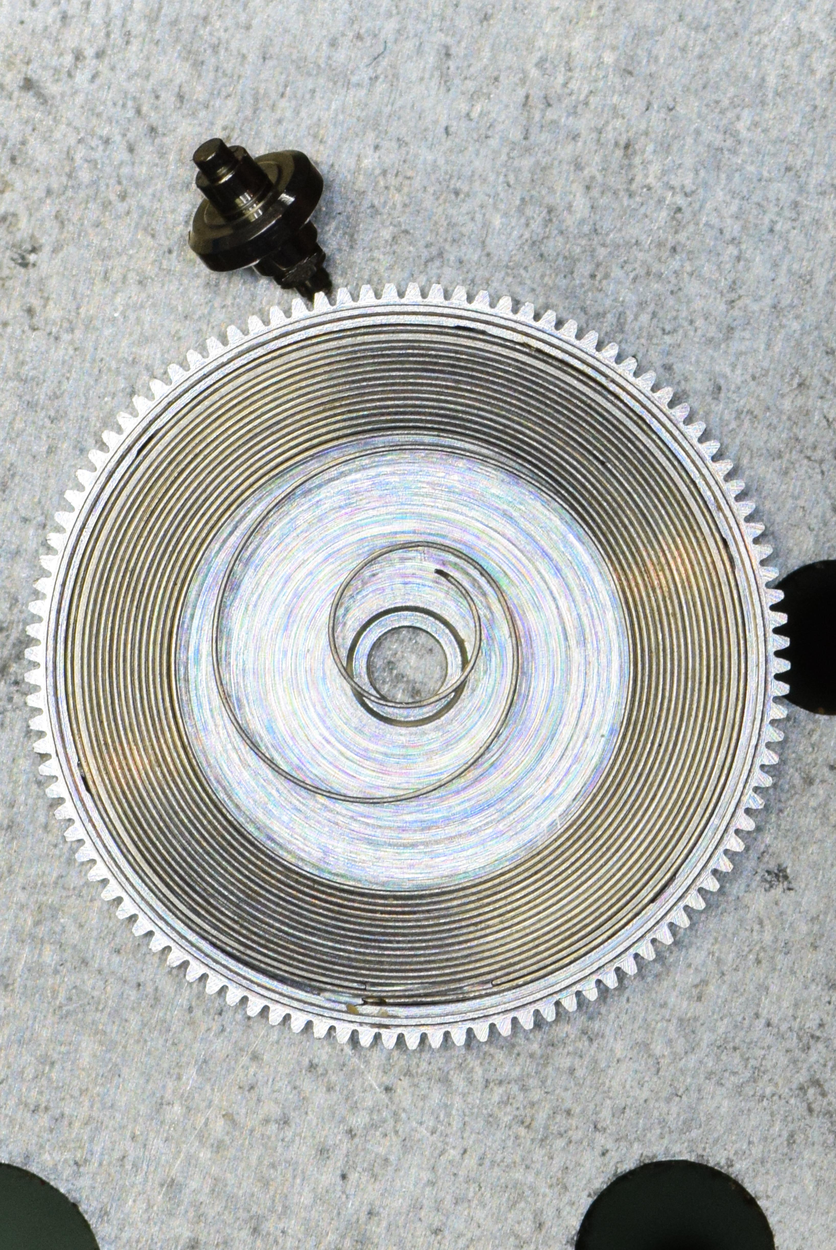
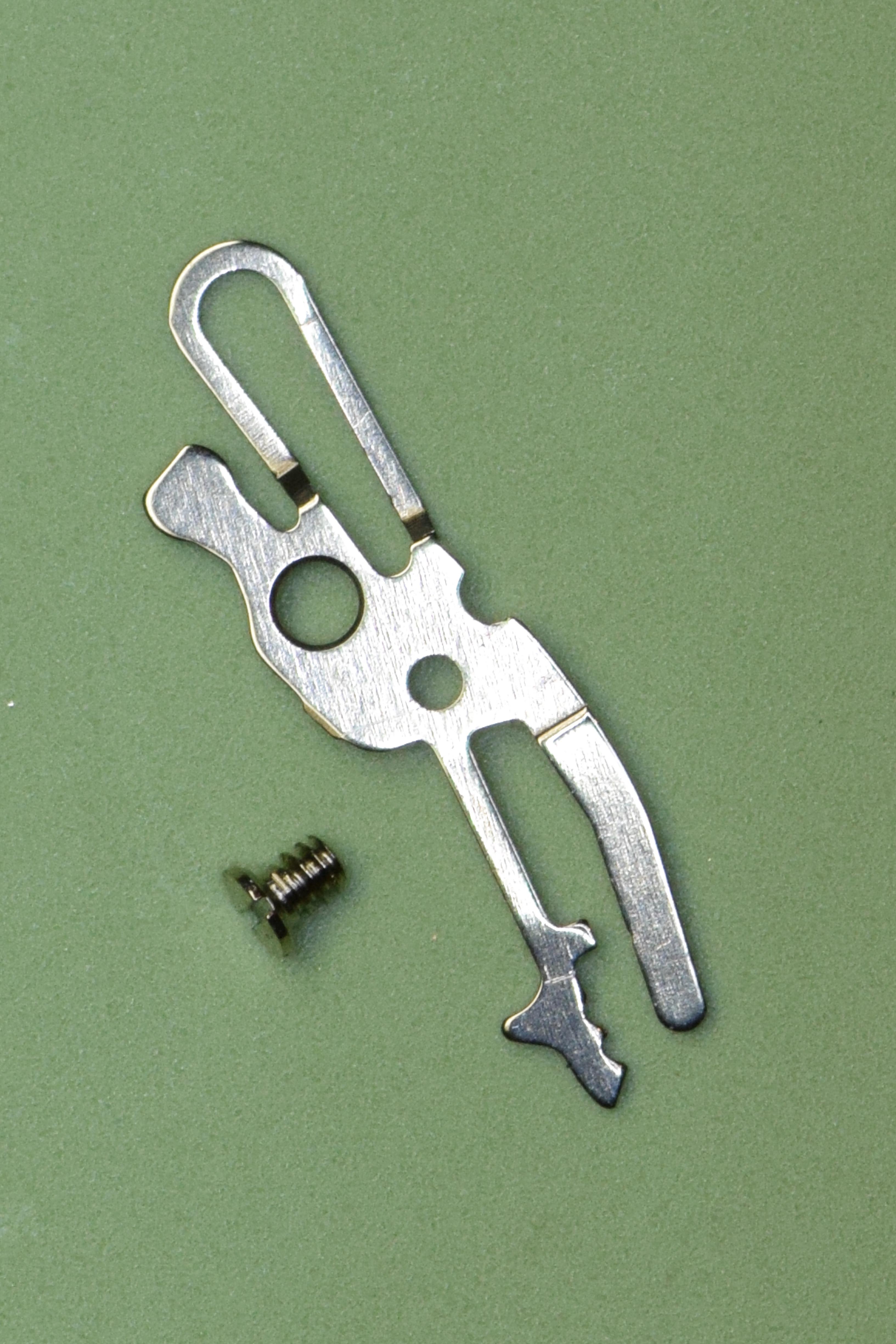
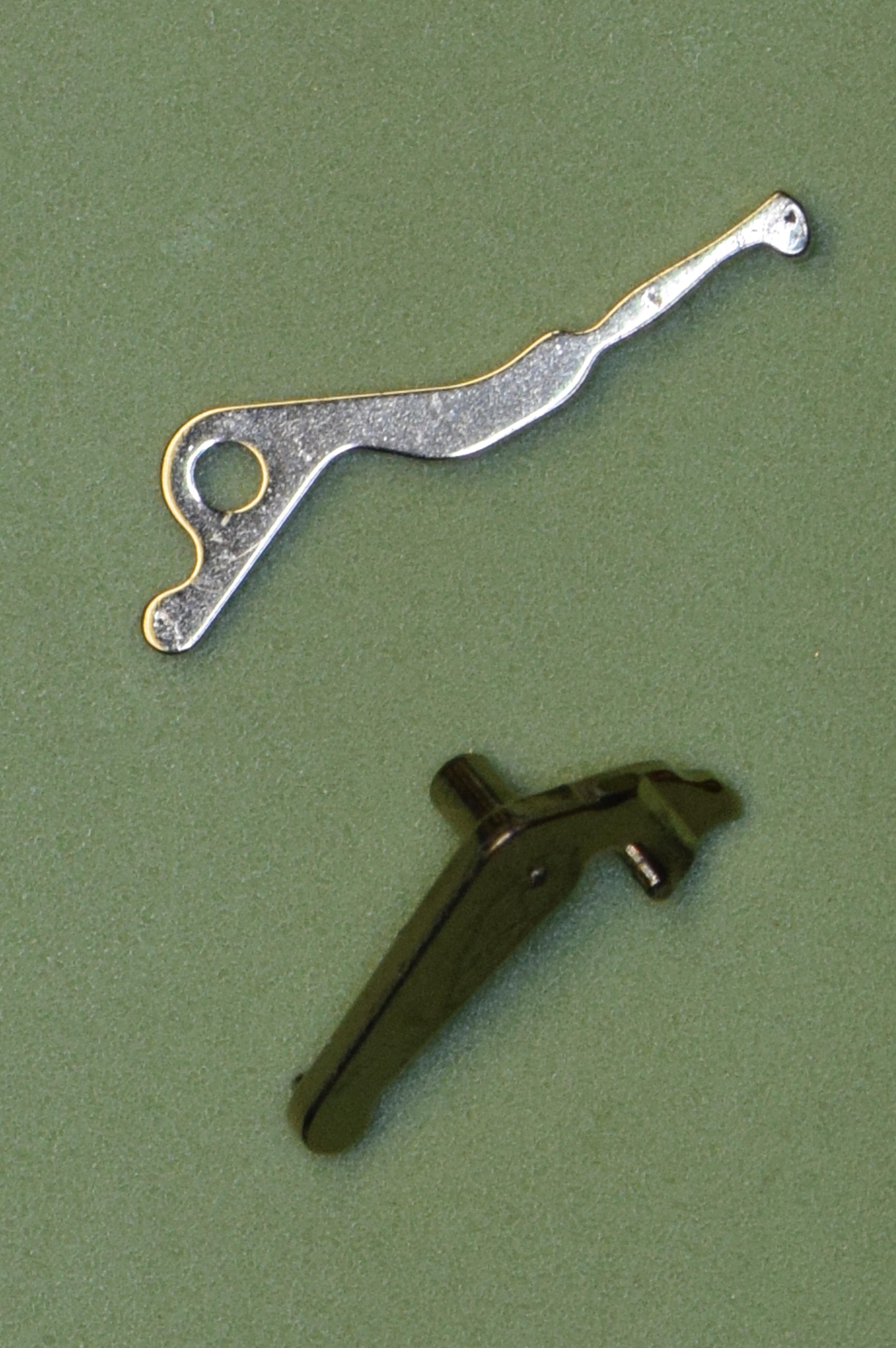
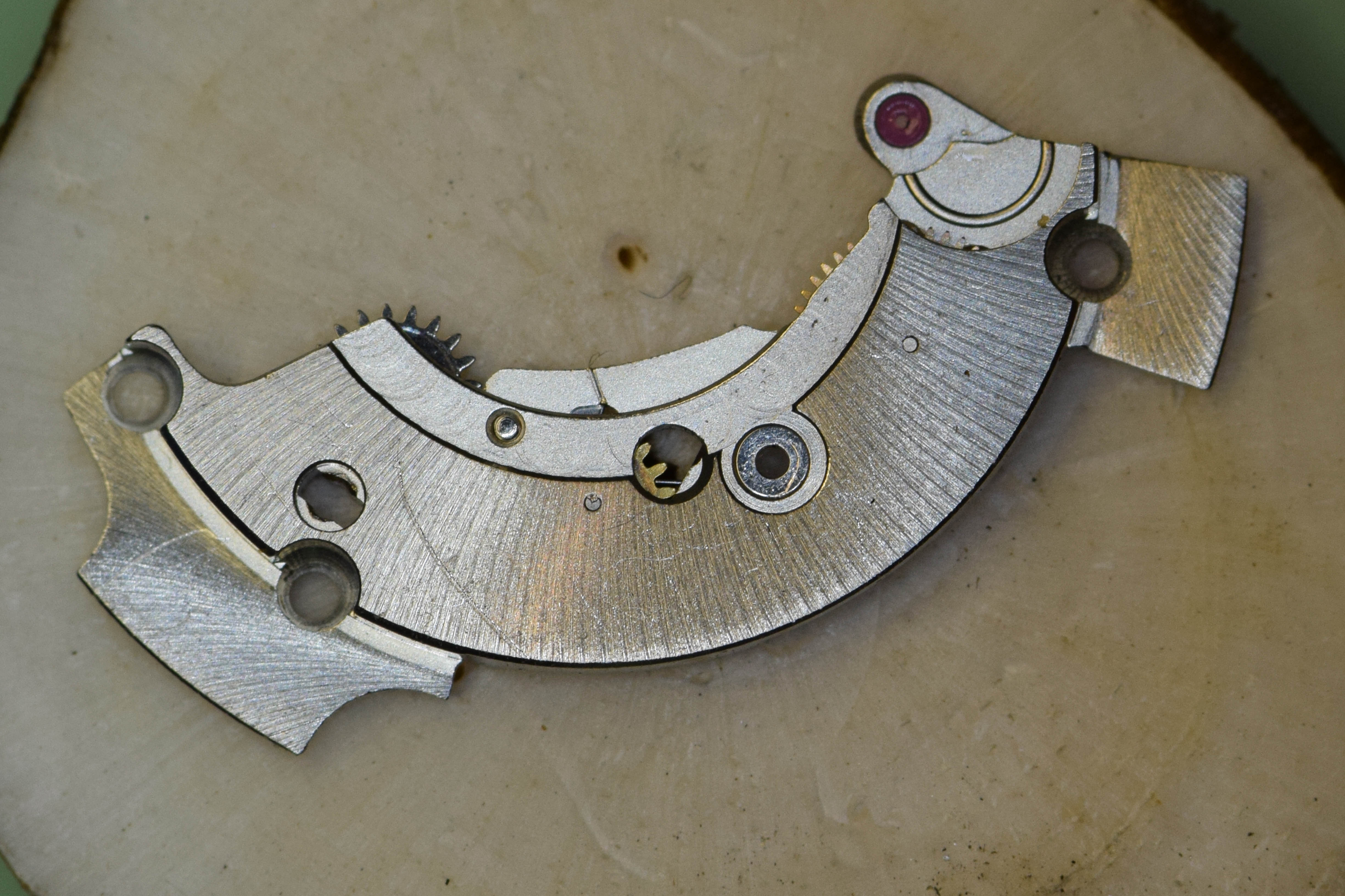
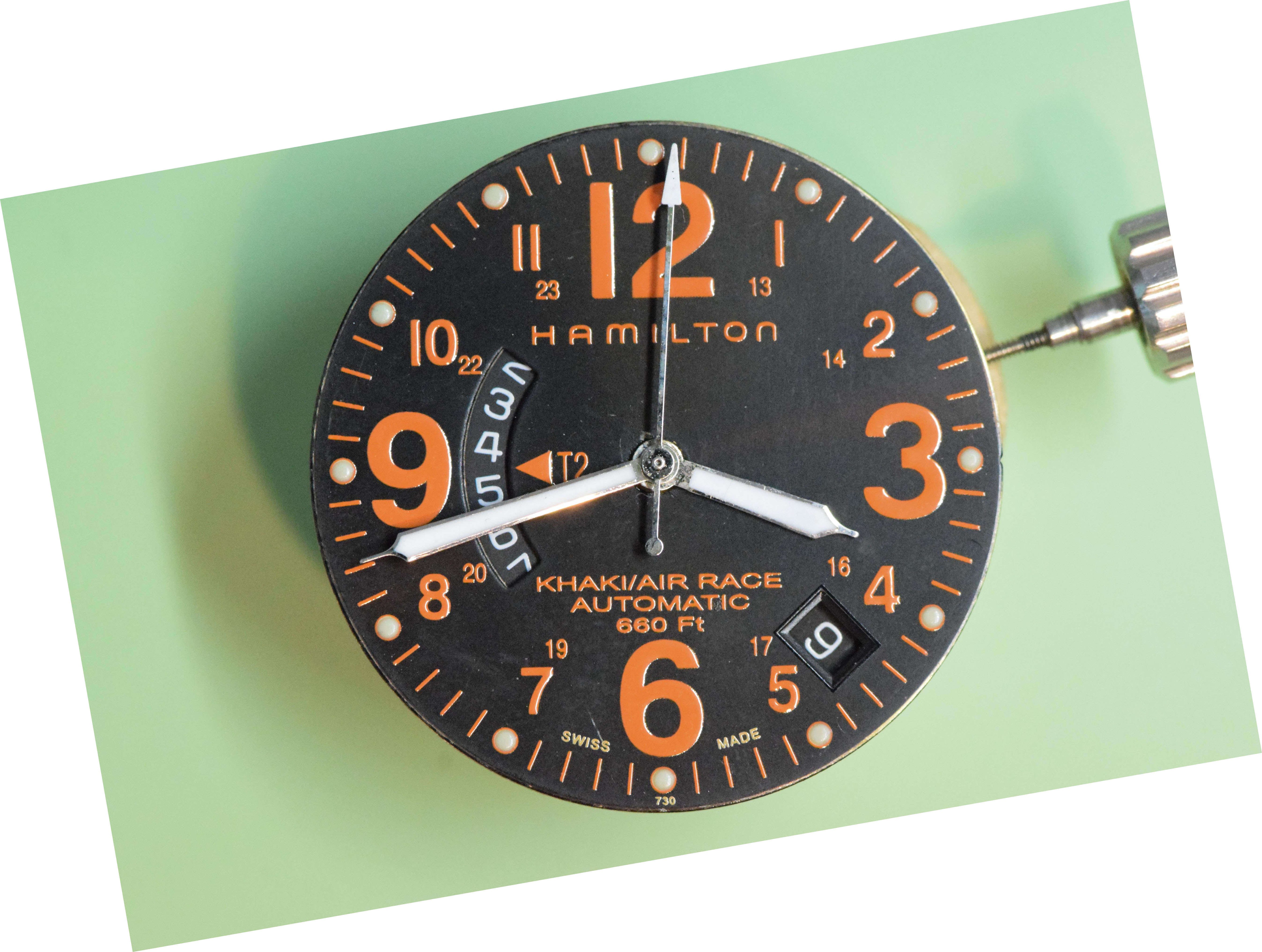
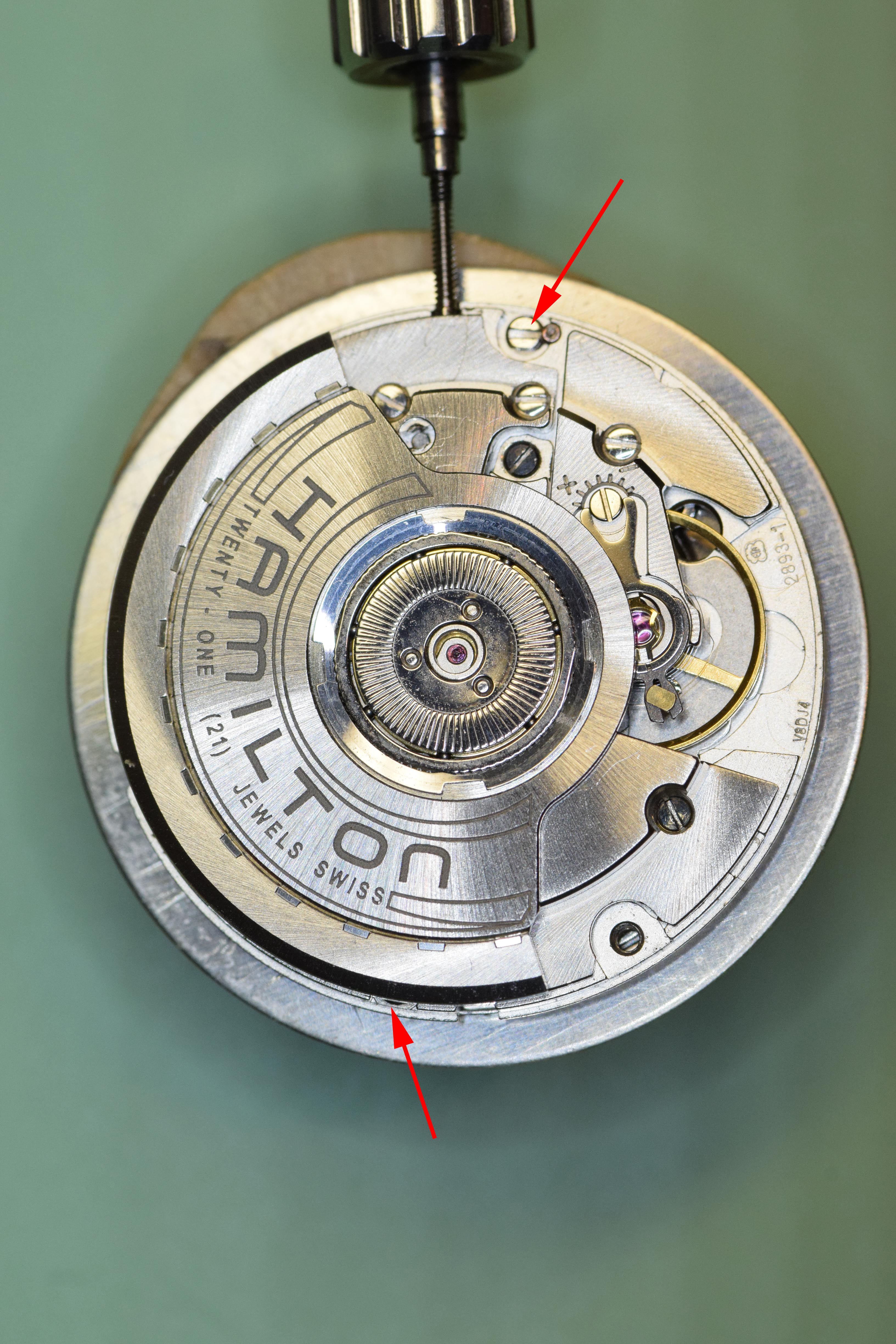
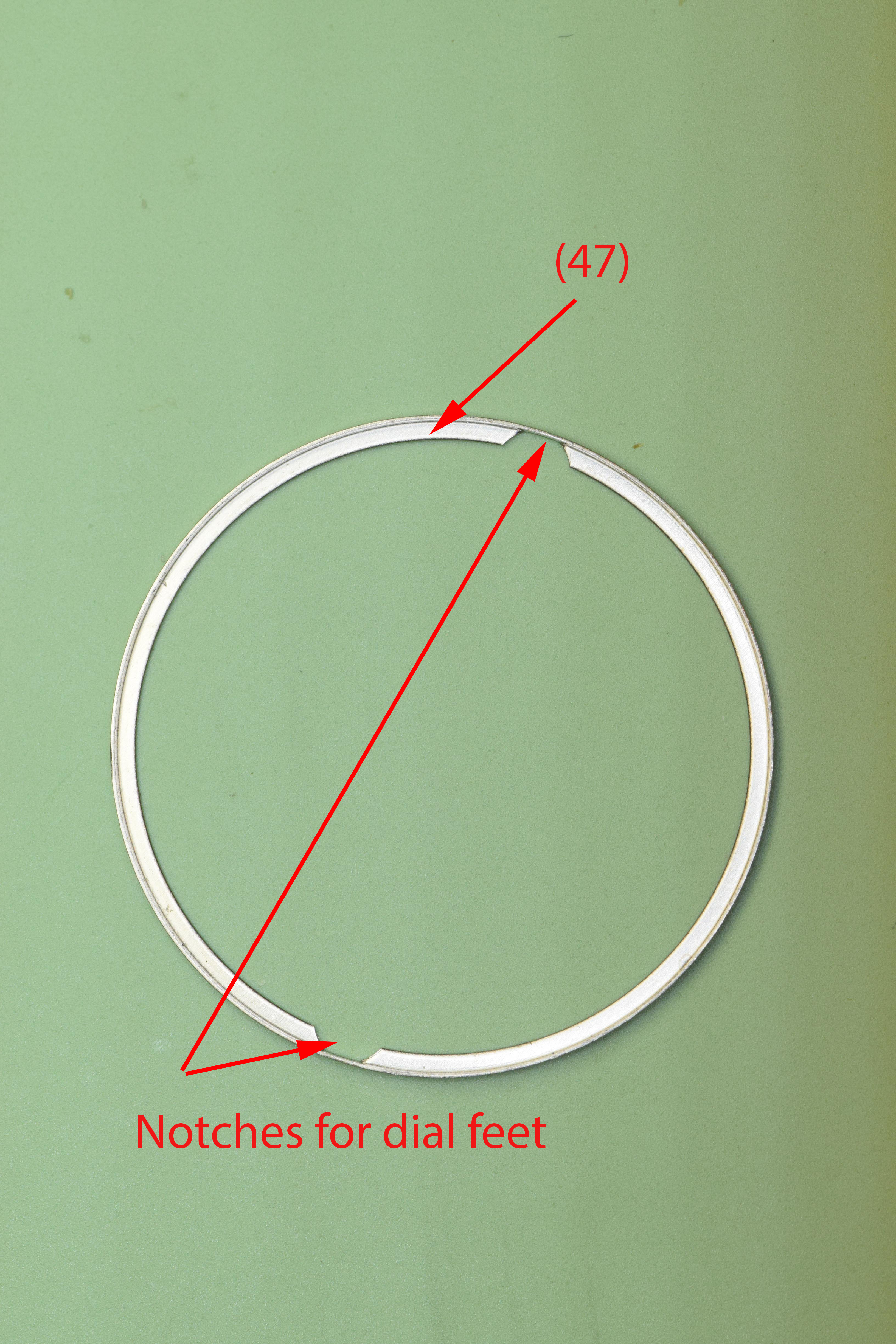
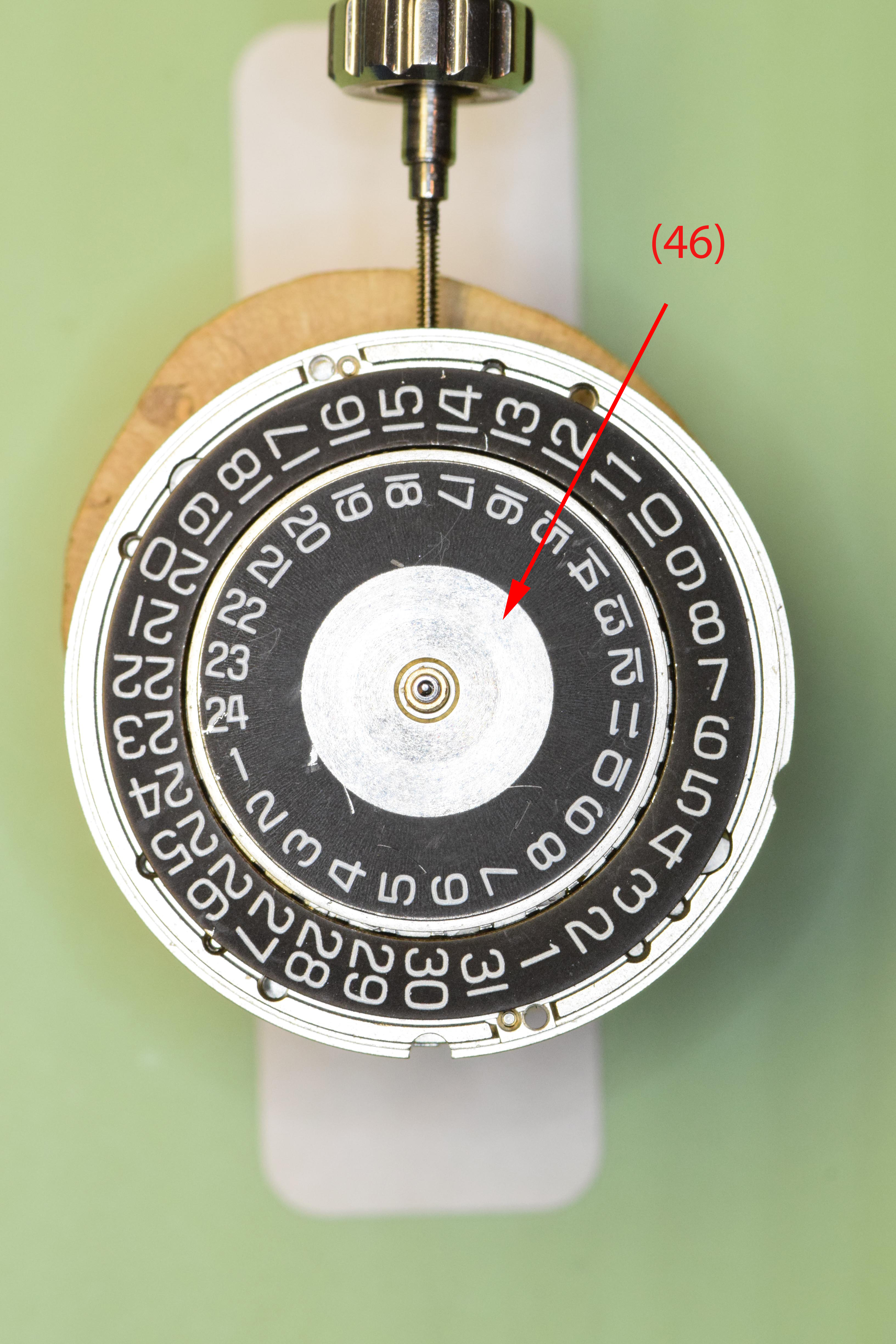
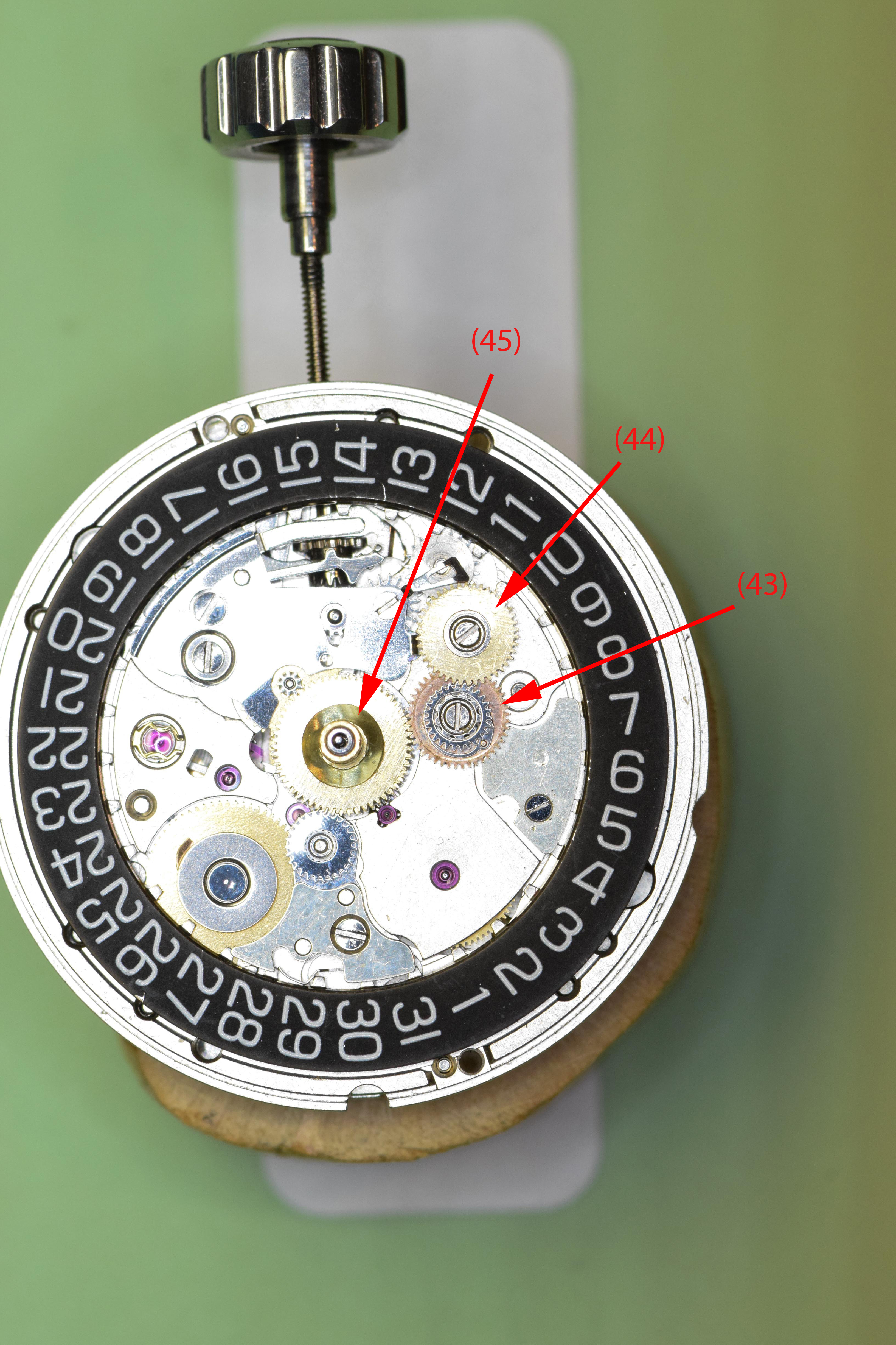
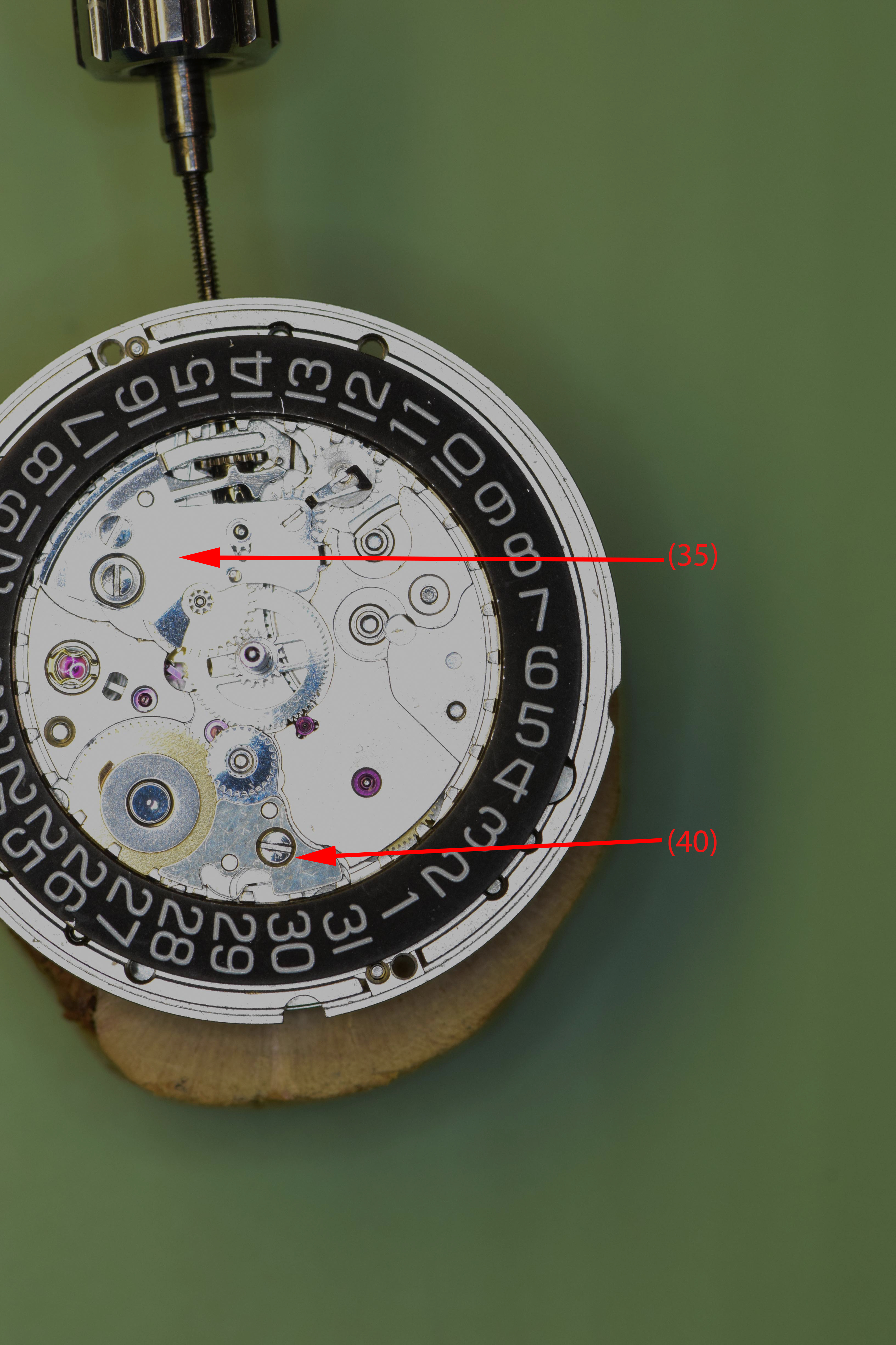
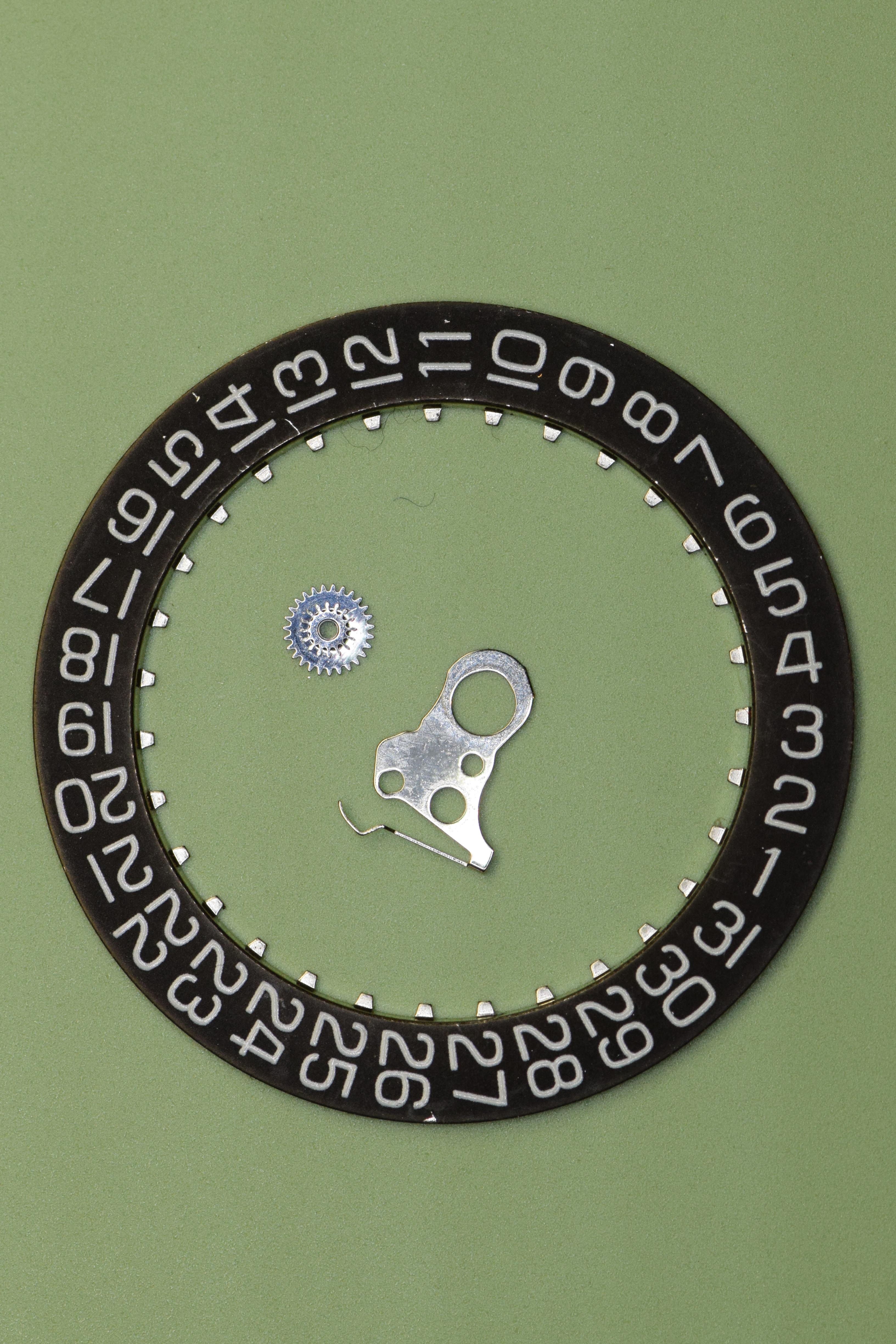
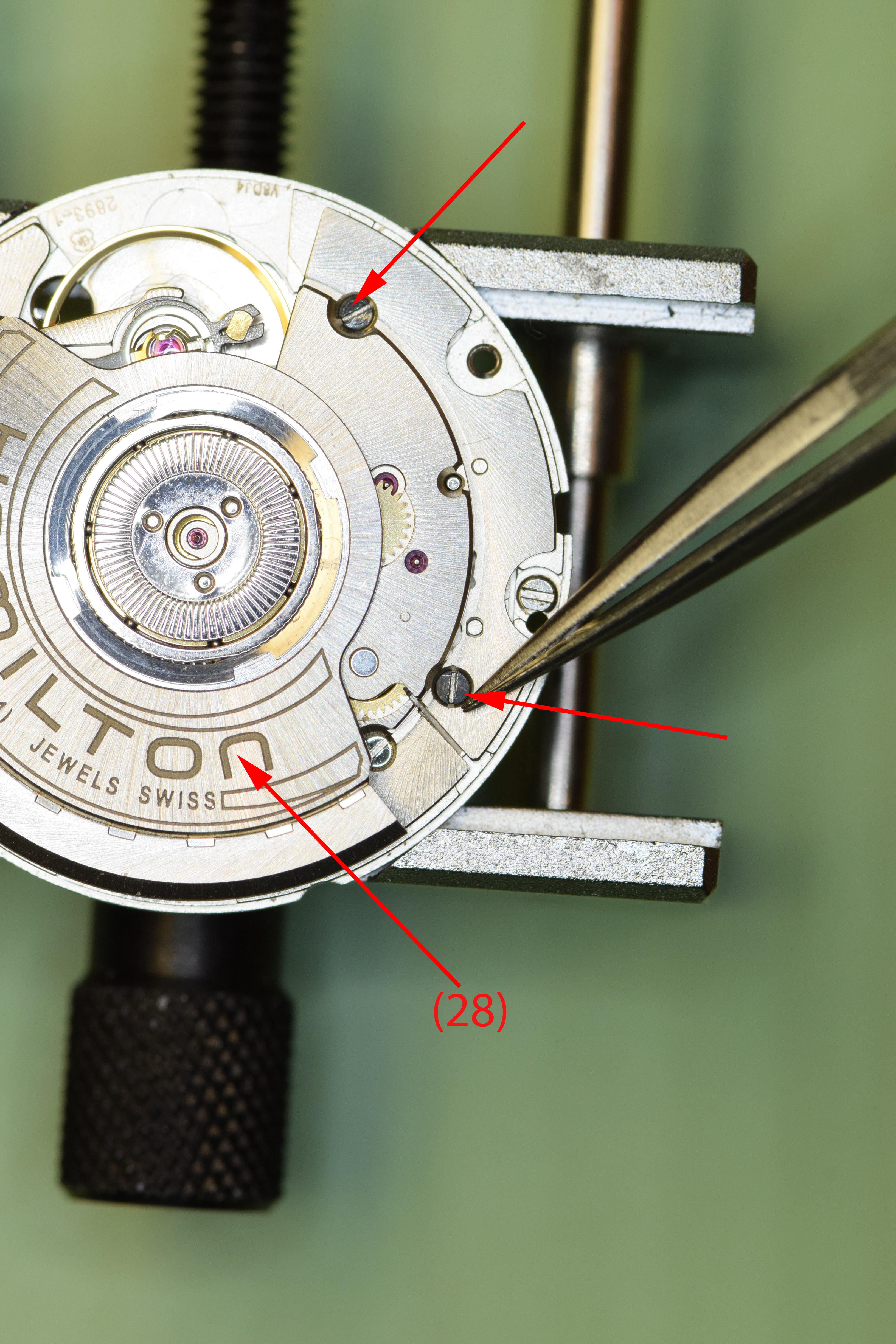
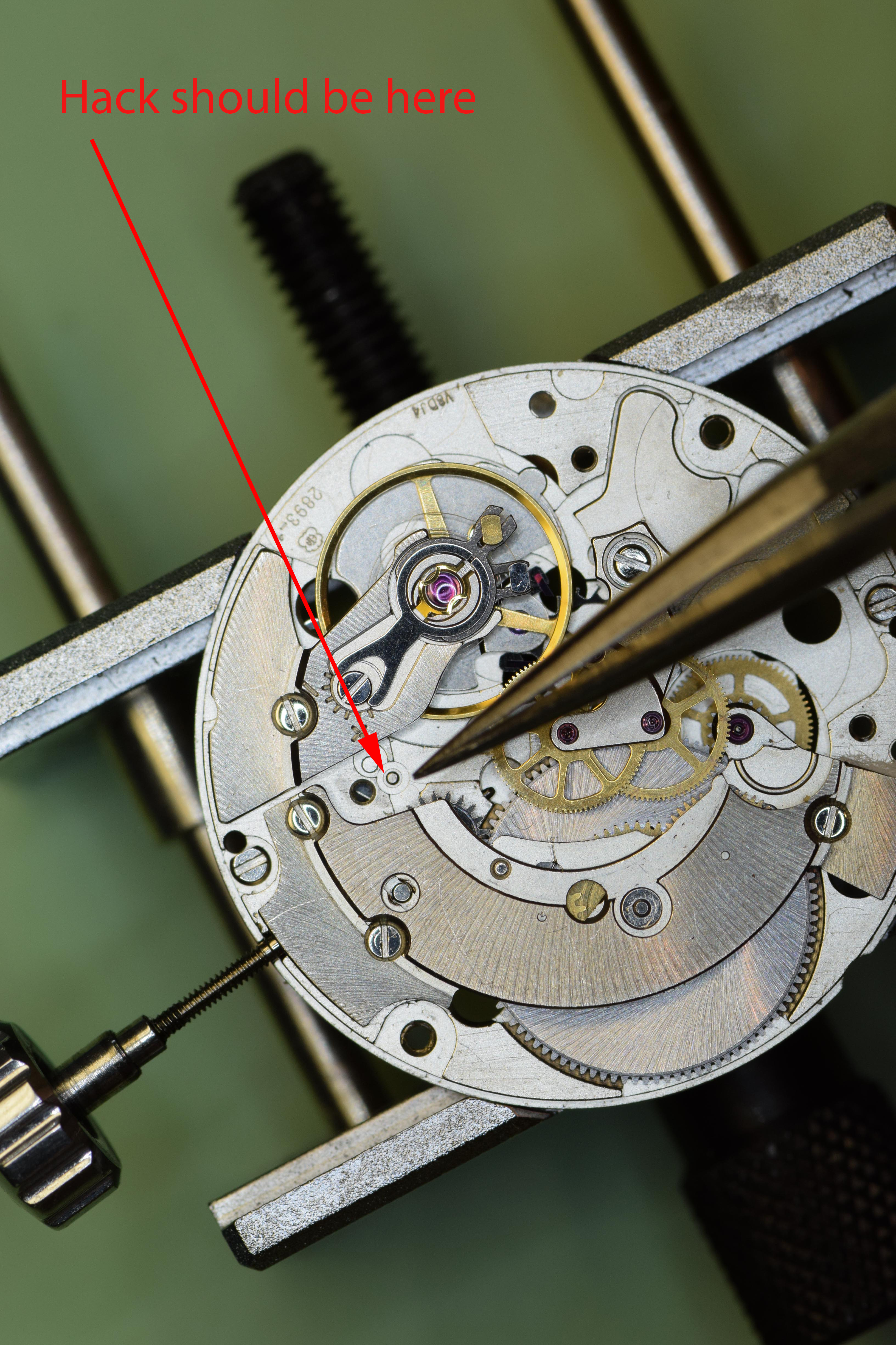
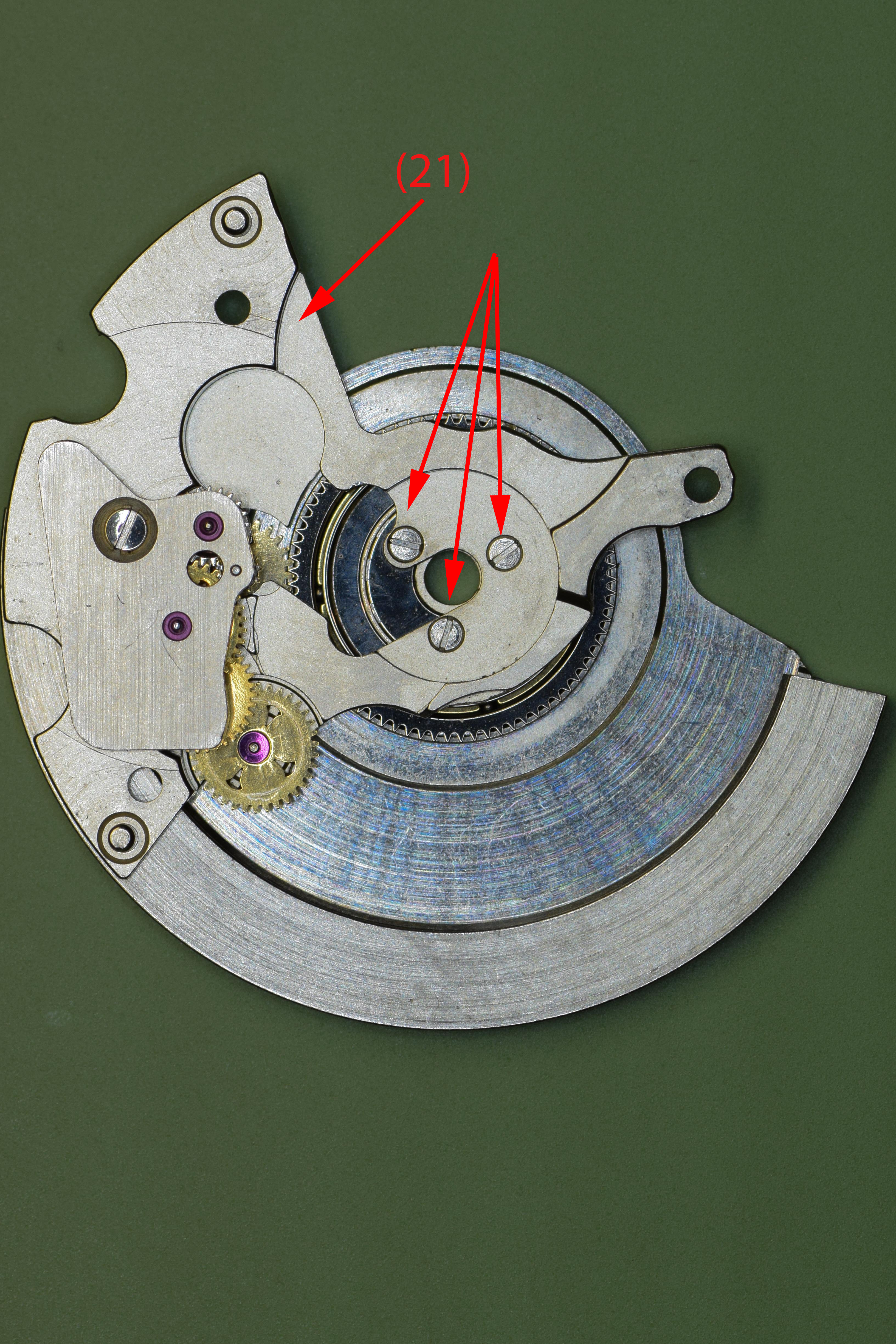
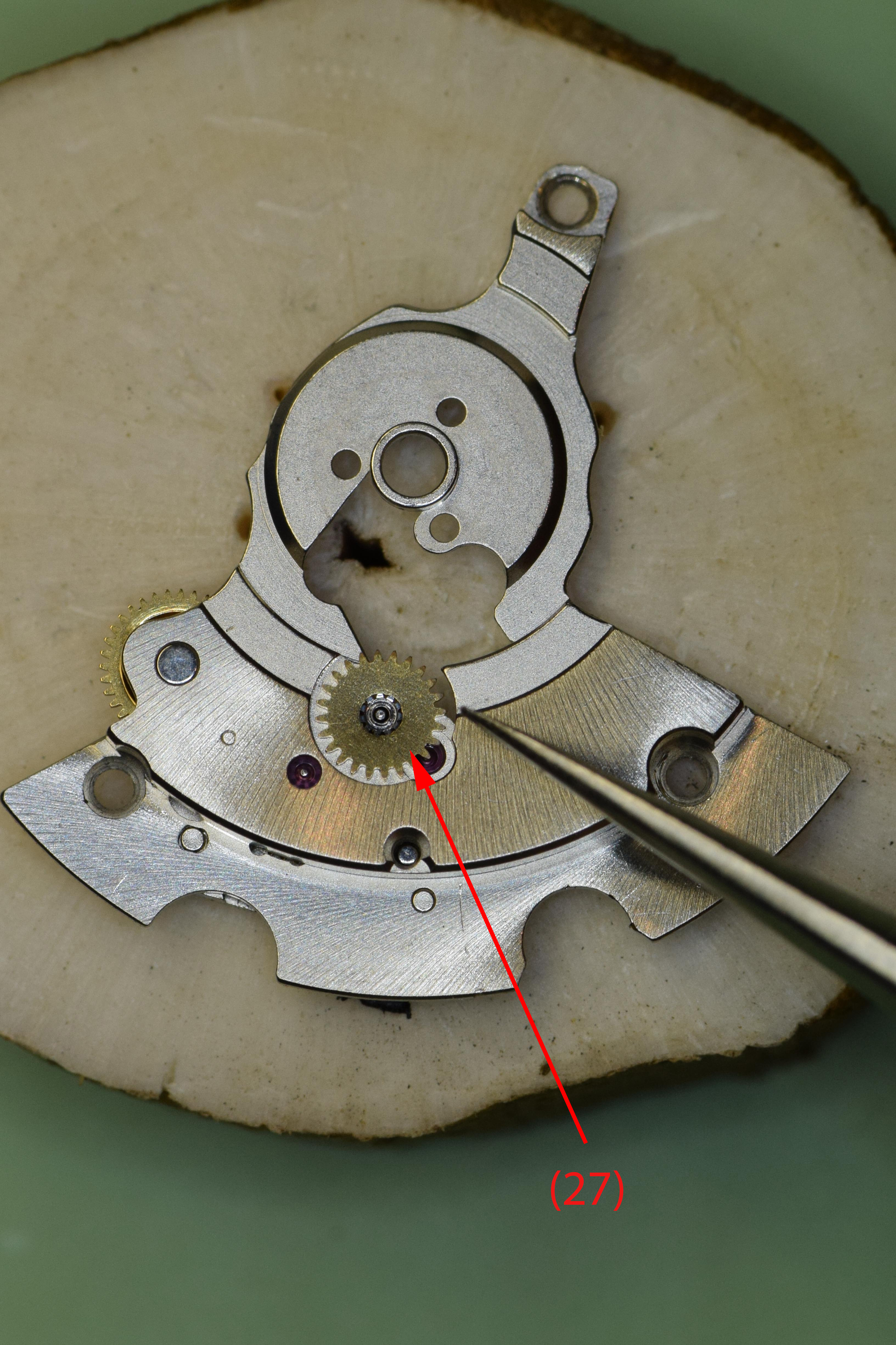
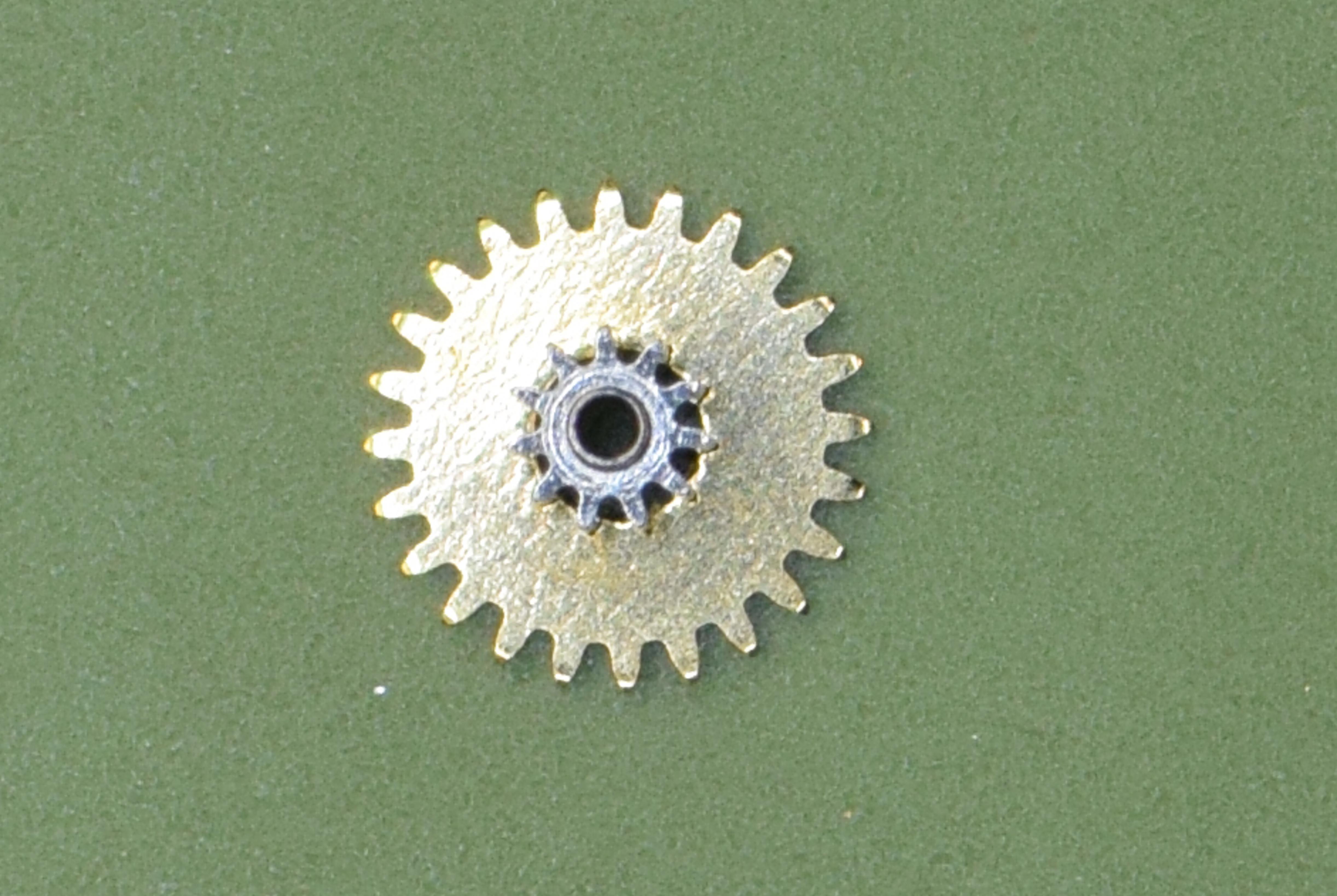
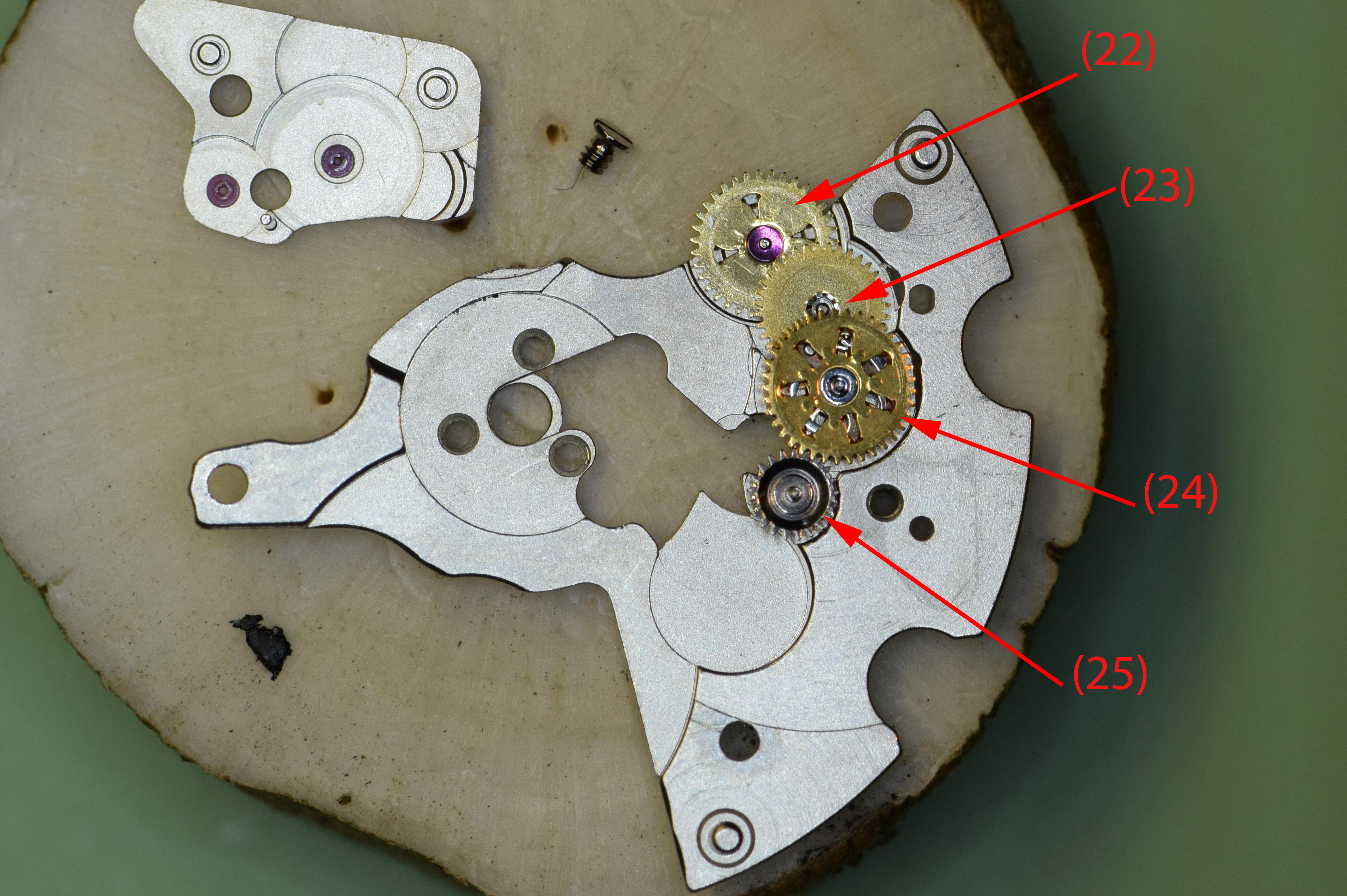
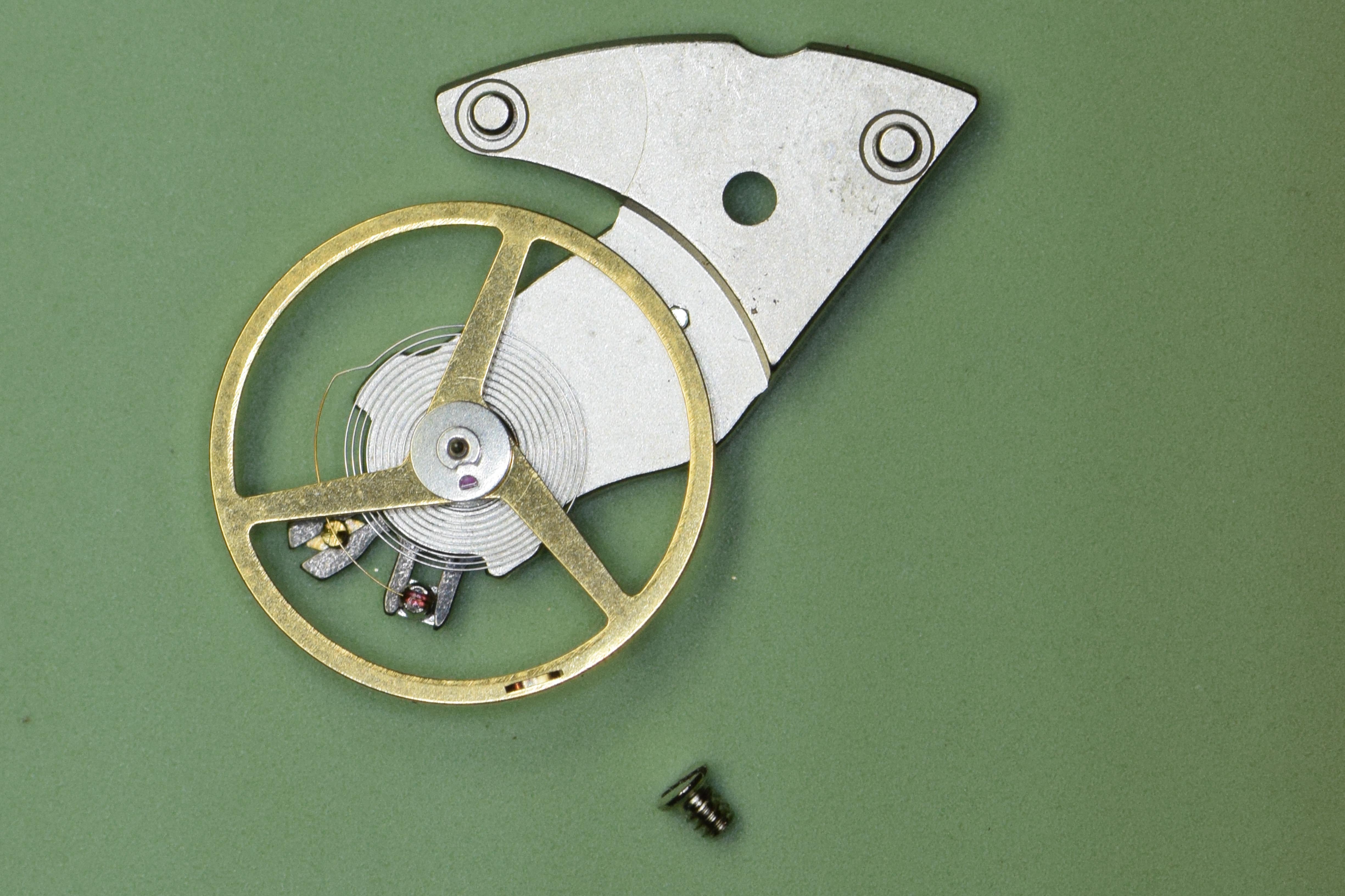
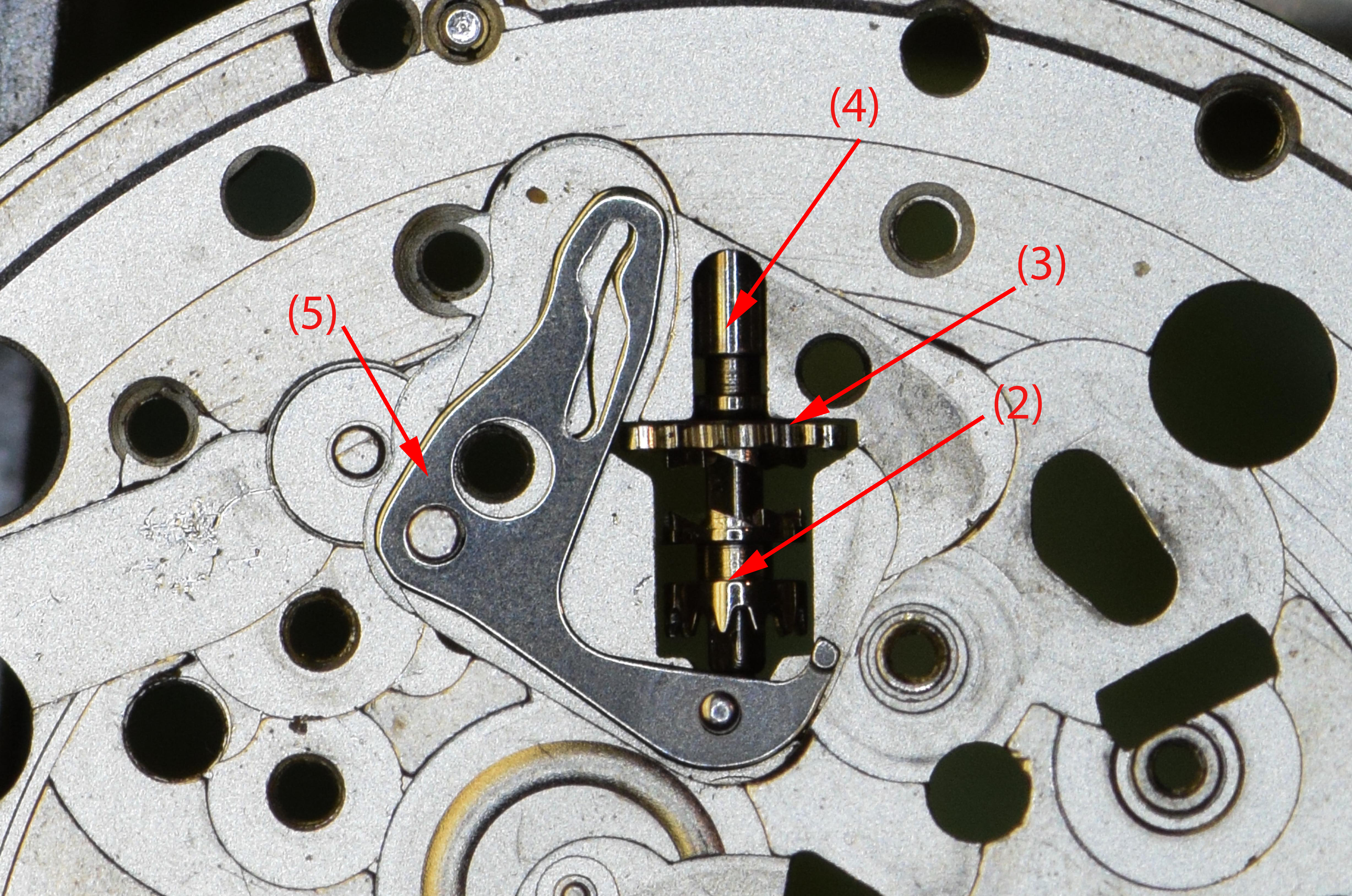
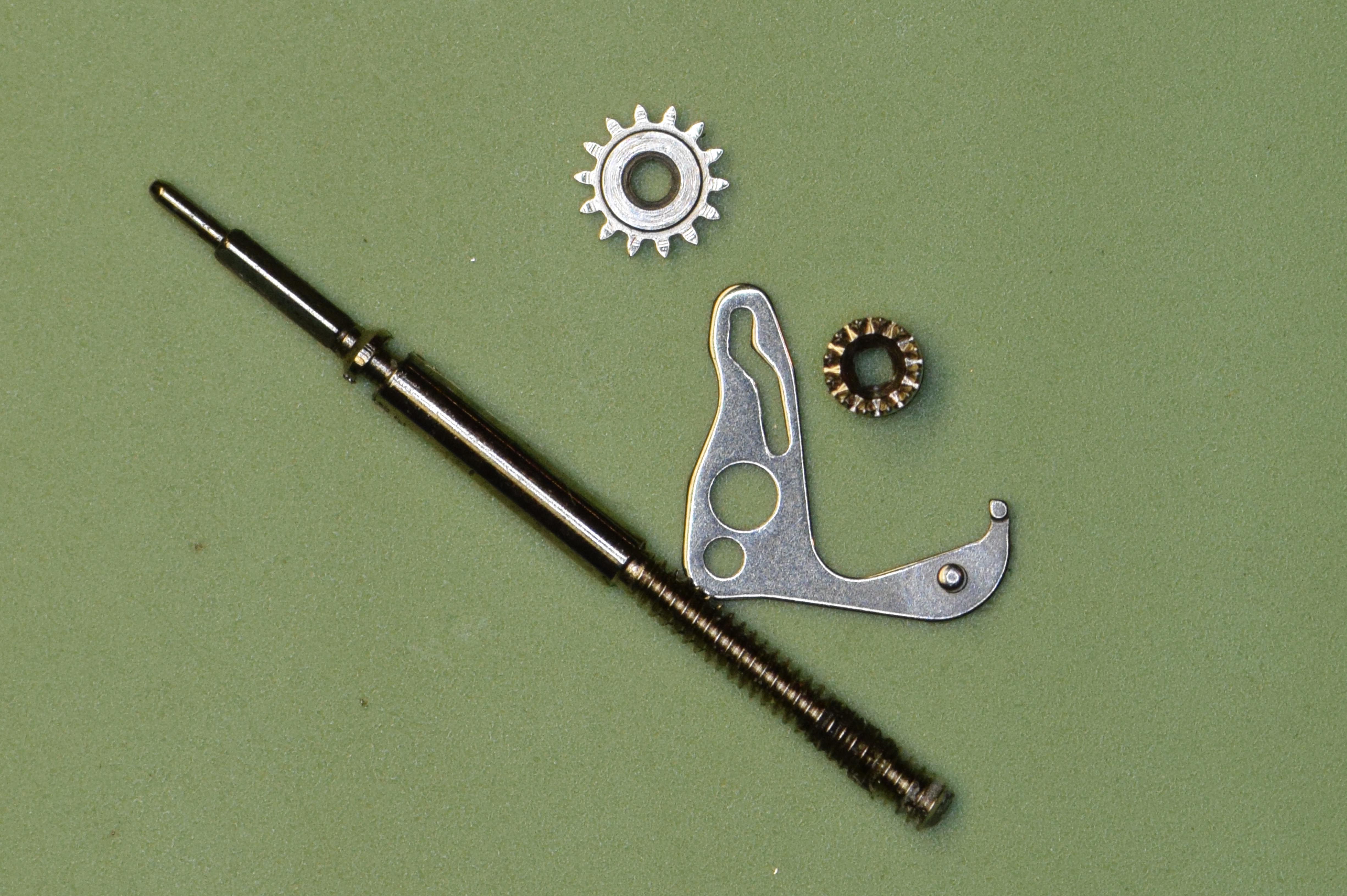
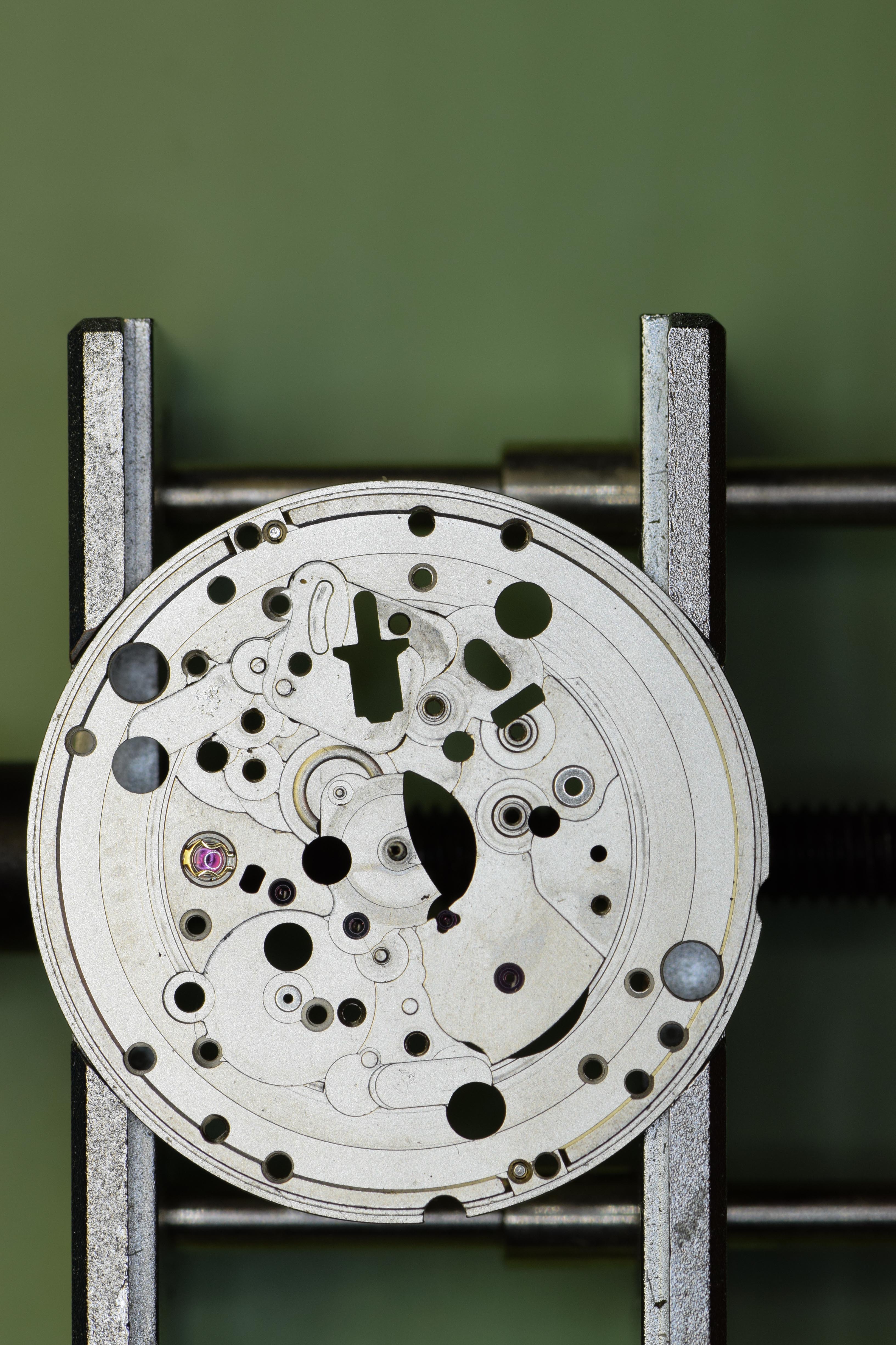
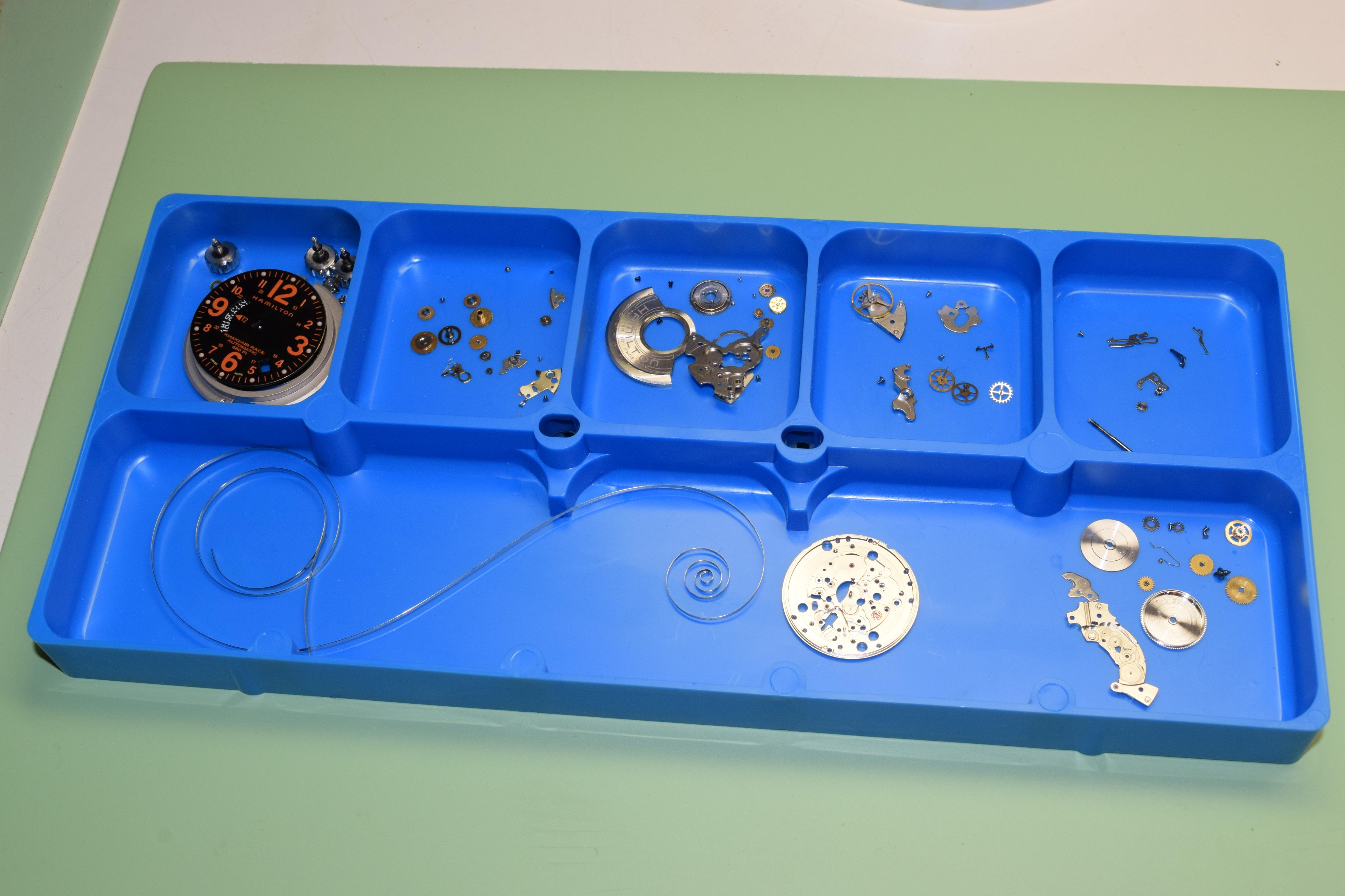
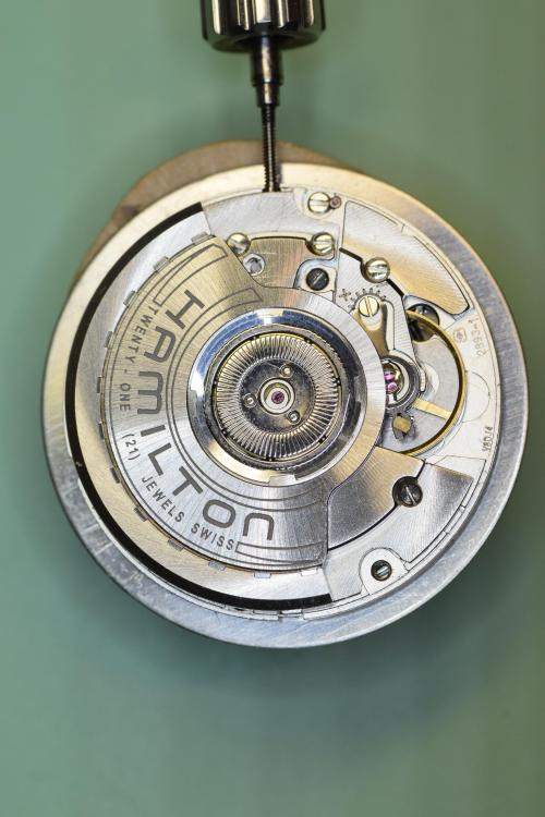
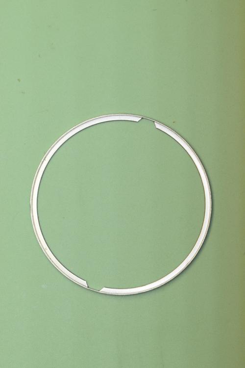
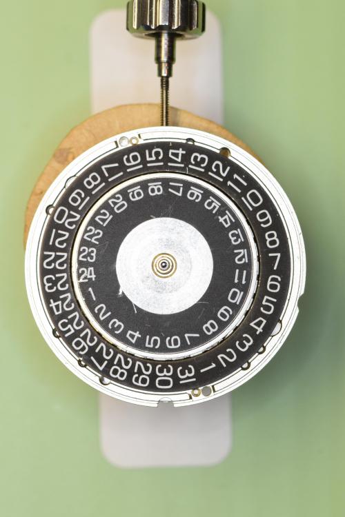
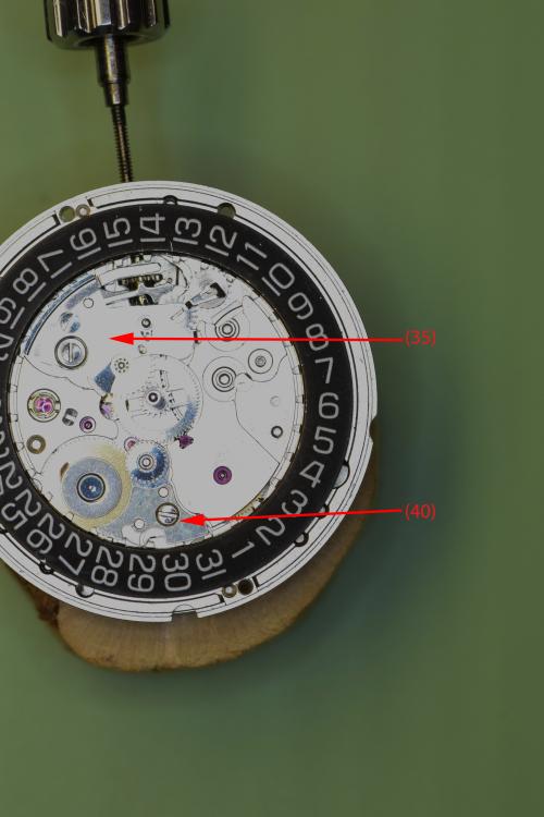
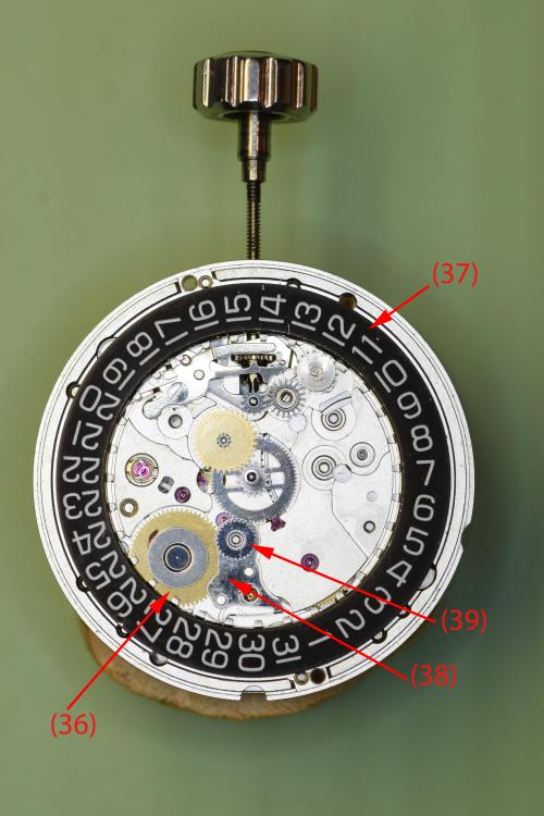
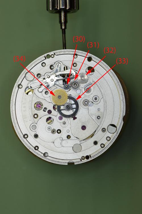
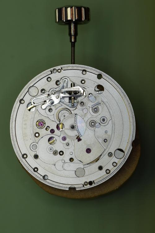
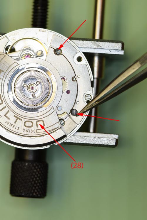
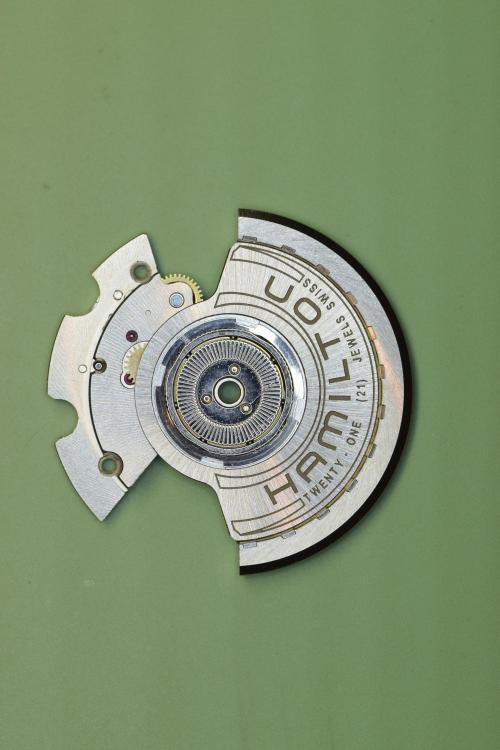
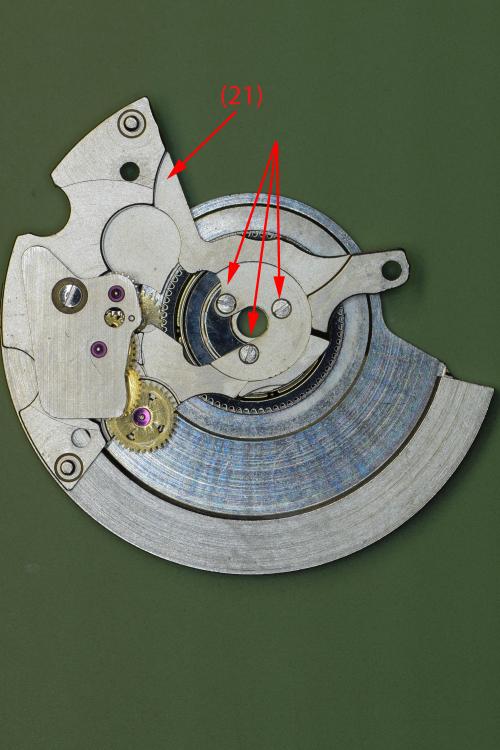
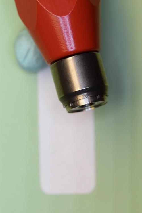
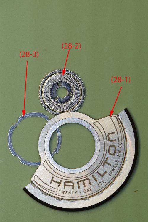
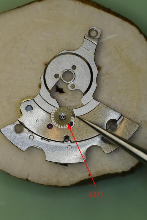
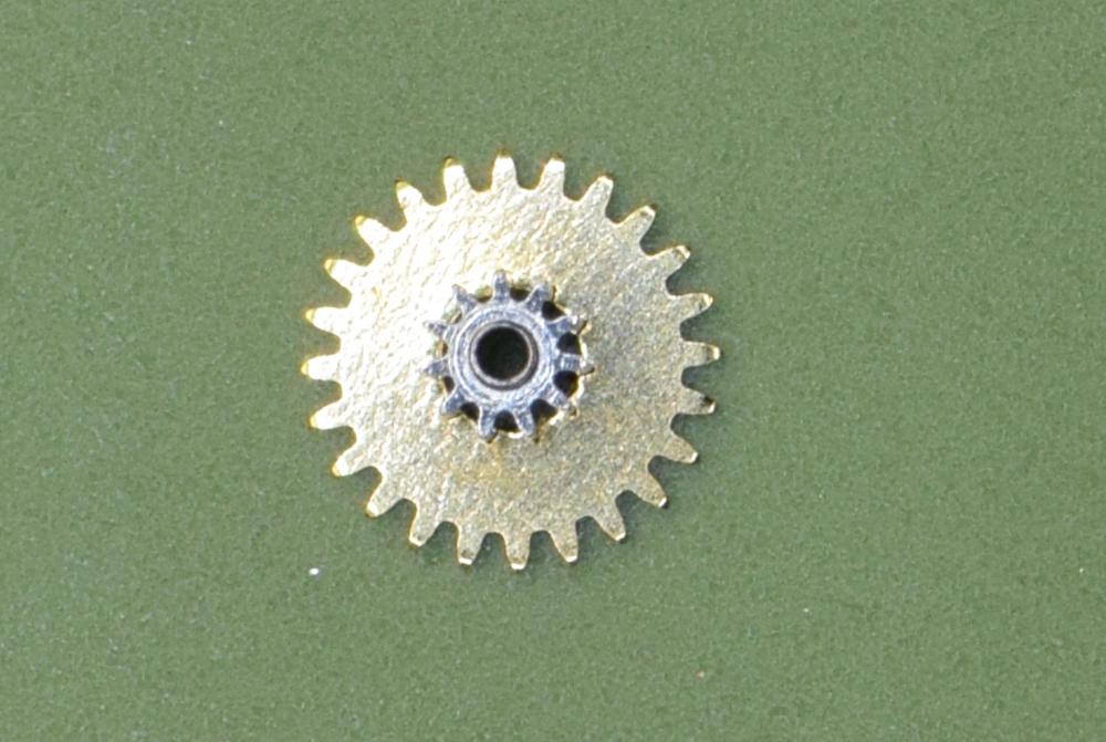
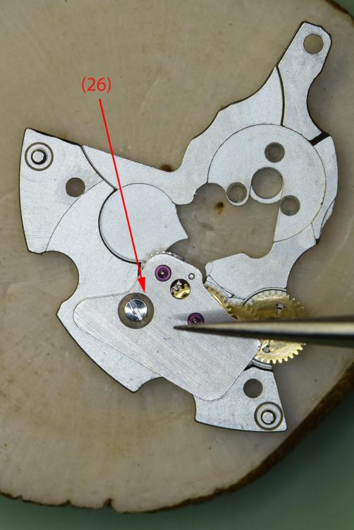
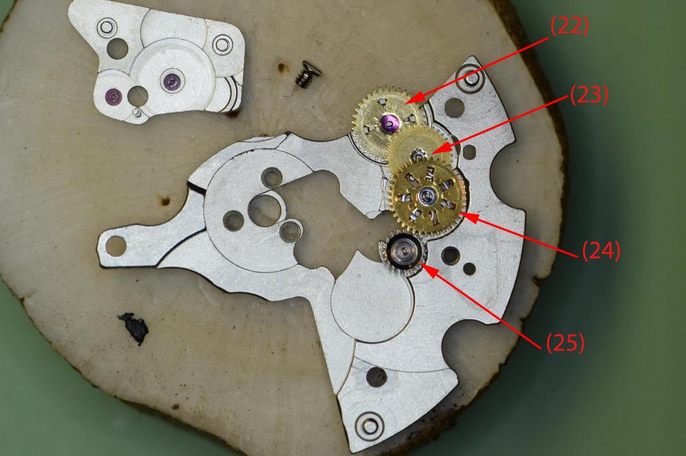
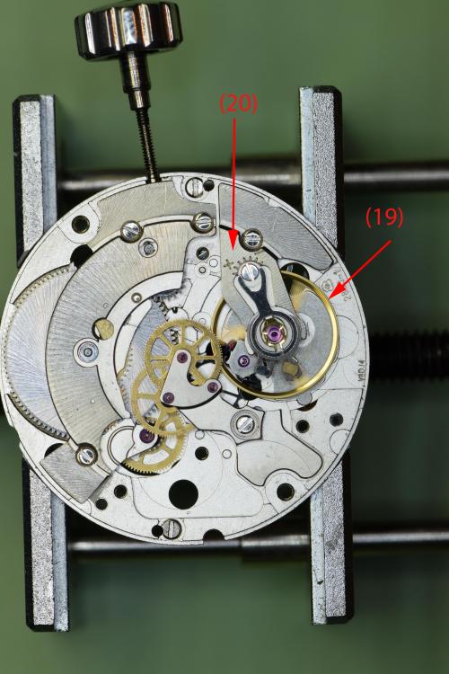
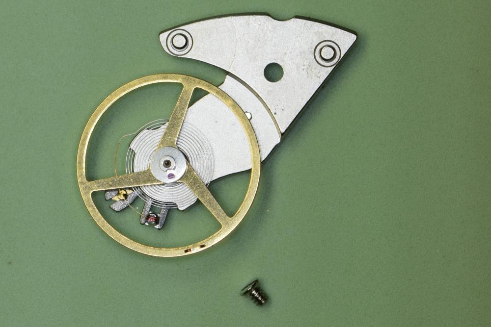
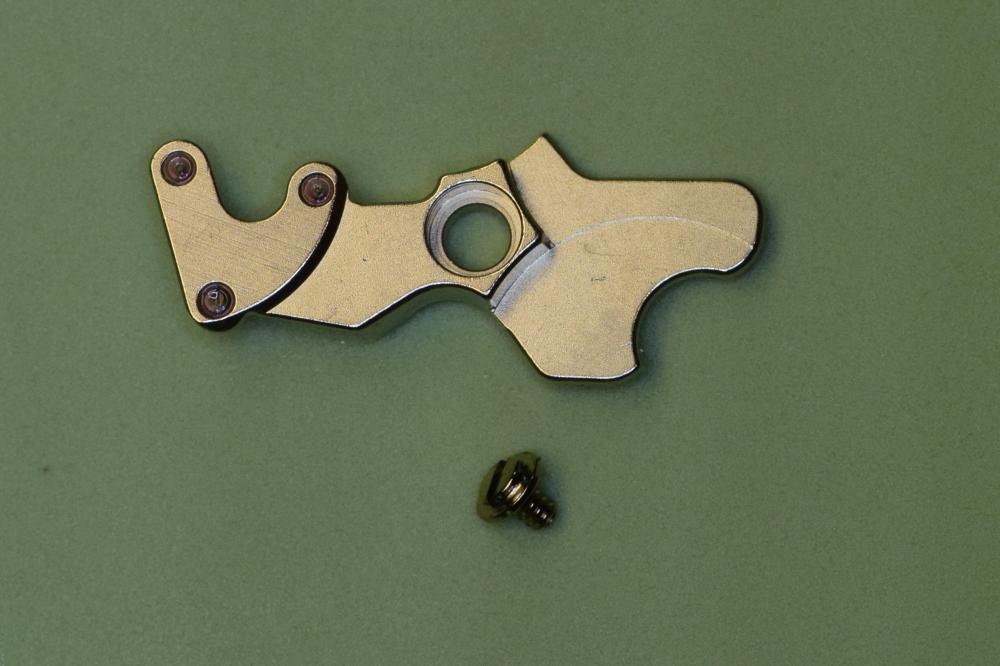
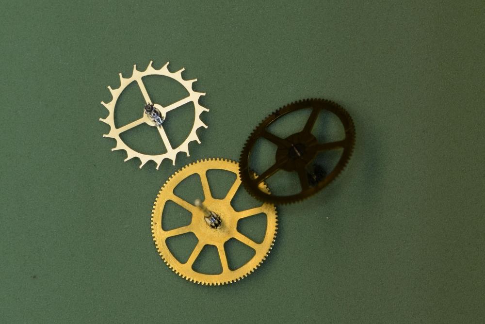
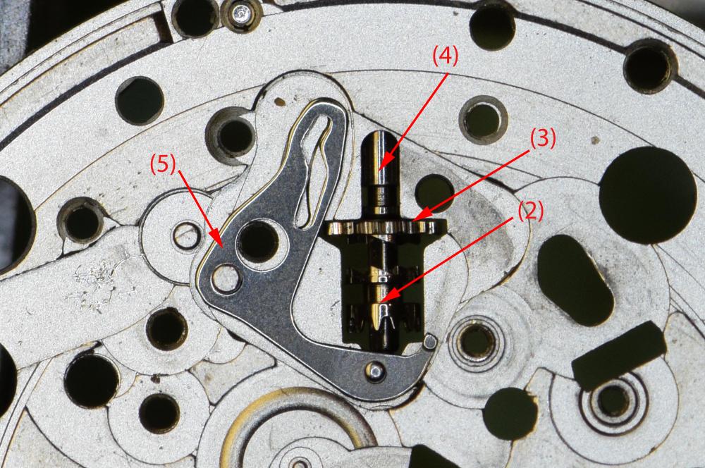
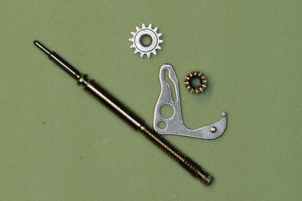
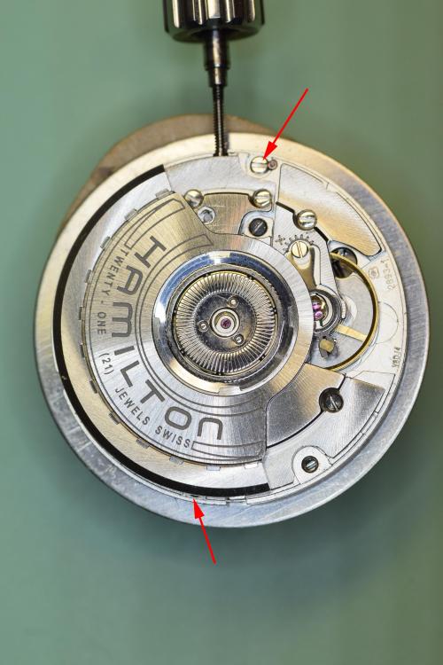
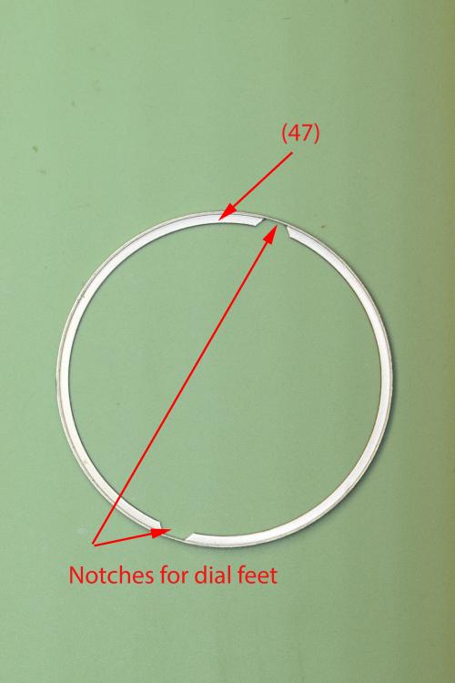
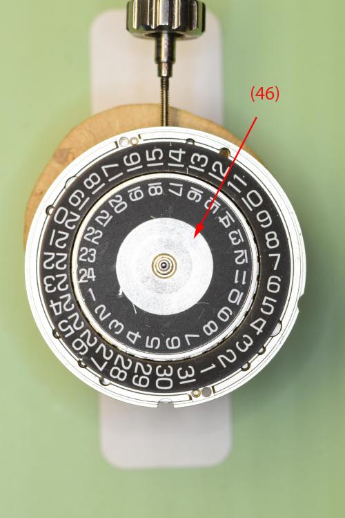
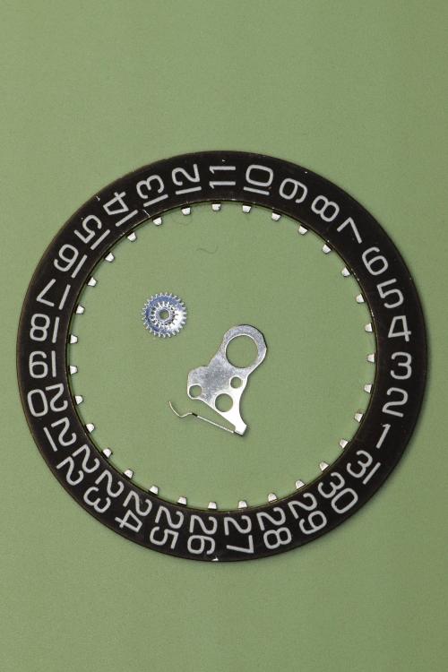
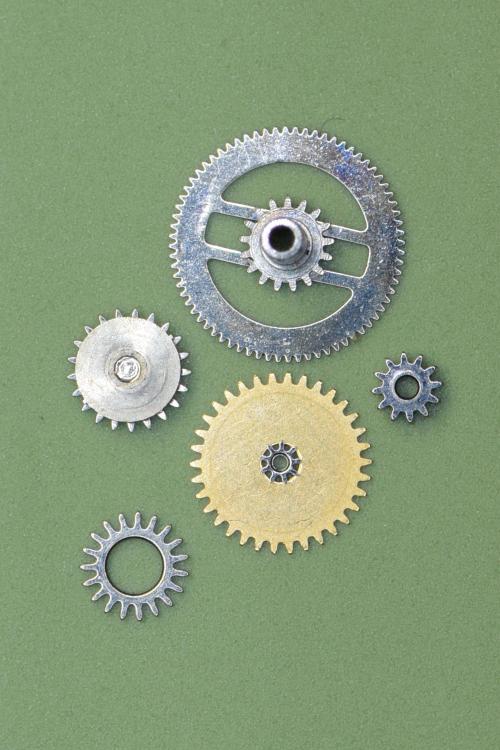
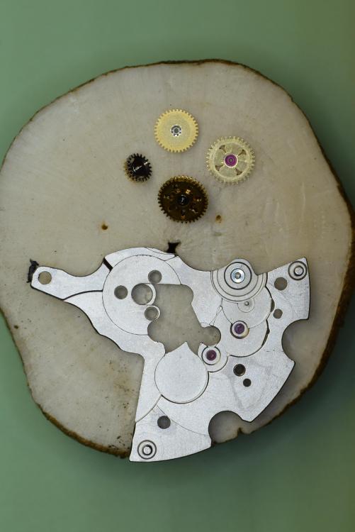
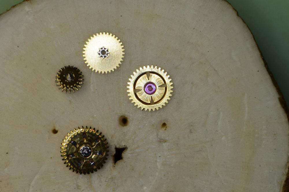
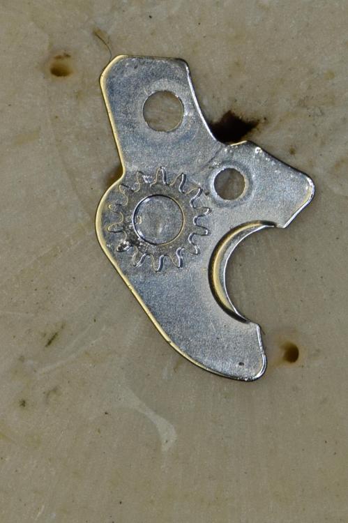
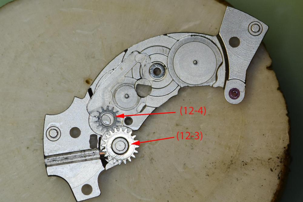
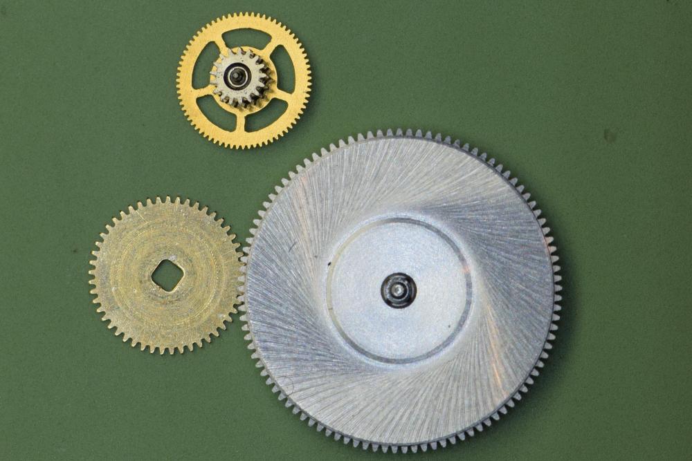
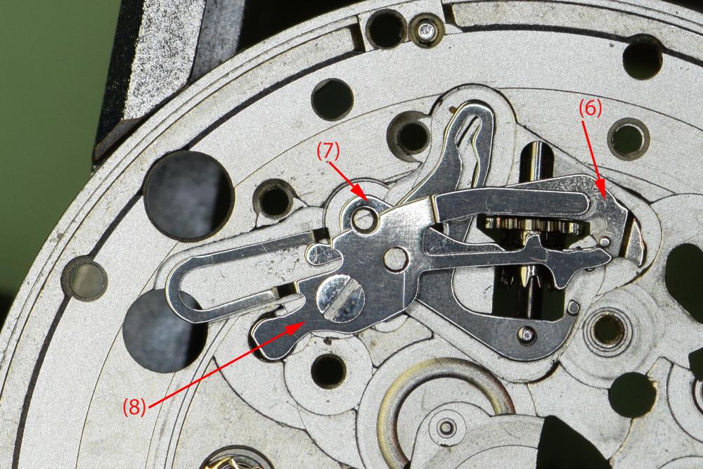
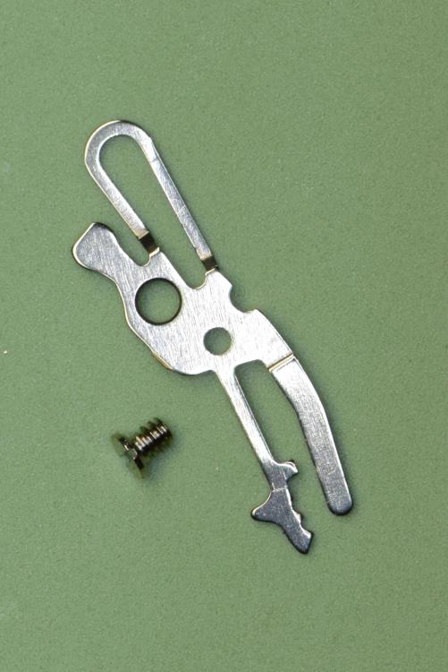
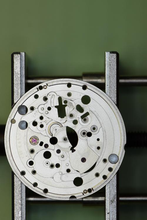
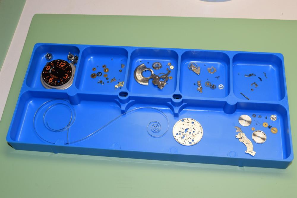
Service Walk Through – ETA 2893-1 / Hamilton Khaki: Part 1 - Disassembly This is part 1 of my service of a Hamilton Khaki – dual time zone automatic based on the ETA 2893-1 movement. I purchased the watch on eBay and it runs for a short time then stops. Looks like it could use a good cleaning. Note that the part numbers in the images and text are consistent with those found in the ETA technical document for this movement. Disassembly of this movement is quite straightforward. The only "special" tool you need would be an oscillating weight bolt tool - and you only need this if you intend to remove the ball bearing assembly from the oscillating weight, which really isn't required. In this tear down I do use the tool - only because I recently acquired it and wanted to see how it worked Off we go.... The dial shows evidence of some sloppy workmanship in the watch's past – several scratches from prior hand removal. Here you see the back of the 2893-1 with its automatic rotor - nicely signed Hamilton. The arrows indicate the location of the dial screws which secure the dial to the movement. These screws have a flat. Turn them just enough so the flat is facing the dial foot and the dial pops right off. Secure the screws so they don’t pop off during cleaning. Preparing to remove the hands – with a safety sheet in place. After removing the dial, remove the Dial Support Ring (47). This ring keeps the dial the proper distance from the second timezone disc. Without it, the disc will rub against the dial. Remove the second timezone disc, or what ETA calls the Universal Hour Indicator (46) from the center. This is a bit tricky as there’s no obvious place to grip it. I used two very small screwdrivers on each side to lift the indicator straight up. Be careful not to scratch it! With the disc removed, we can now remove the Dial Washer / Friction Spring (45), Corrector Setting Wheel (44) and Hour Indicator Driving Wheel (43). The Hour Wheel (42) can now be lifted off, followed by the Additional Indicator Maintaining Plate (41). Next components to remove are the Date Indicator Maintaining Plate (40) and the Minute Train Bridge (35). We move on to remove the Intermediate Date Wheel (39). The Date Jumper (38) has also been exposed when we removed the maintaining plate, so we remove it. Finally, we remove the Date Indicator (37) and the Date Indicator Driving Wheel (36). Now on to some of the motion and keyless work. We remove the Minute Wheel (34), Cannon Pinion with Driving Wheel (33), Double Corrector (32), Date Corrector Intermediate Setting Wheel (31) and Setting Wheel (30). This side is almost complete. We leave the setting components in place. Removing them now would be problematic as we have yet to release tension from the mainspring. Flip the movement over and remove the automatic work. After removing the 3 blue screws (seen in the previous 2 pics) we lift the entire unit up gently by the Oscillating Weight (28). With the automatic work out of the way – I notice that the Stop Lever (Hack) is missing! Will try and source one. Back to the automatic work. Removing these 3 small screws will allow the oscillating weight to come off the Automatic Framework (21). This is a special tool designed to release the Oscillating Weight Bolt I remove the Oscillating Weight Bolt (28-3) and free the Ball Bearing (28-2) from the Oscillating Weight (28-1). There was no compelling reason to disassemble this portion of the movement, but the tool worked as expected! With the Oscillating Weight out of the way, remove the Auxiliary Reverser (27). Flip the unit over once again and remove the screw and Automatic Device Lower Bridge (26). Remove the Reverser (25), Reverser Wheel (24), Reduction Wheel (23) and Intermediate Reduction Wheel (22). A view of the underside of these components – handy when trying to remember which way to reassemble. Remove the single screw and gently lift off the Balance Assembly (20) with the Balance Complete (19). Carefully let the power down by releasing the Click (12-6) and slowly letting the crown wind down. Remove the Pallet Bridge (18) and Pallets (17). Remove the Train Wheel Bridge (16). It is secured with a hefty screw! Remove the Fourth Wheel (15), Third Wheel (14) and Escape Wheel (13). Remove the 3 screws and the Barrel Bridge (12) Flip the bridge over and lift off the Ratchet Wheel Driving Wheel (12-2) Remove the screw and the Click Plate (12-7), followed by the Click (12-6), Intermediate Ratchet Wheel (12-5), Intermediate Crown Wheel (12-4) and Crown Wheel (12-3). Note that the Intermediate Crown Wheel is under the Click Plate. When I removed the plate, the wheel was stuck to it due to some old oil. Here you can see the Intermediate Crown Wheel as it was stuck. This shows the proper placement of the wheels. Remove the Ratchet Wheel (11), the Mainspring Barrel (10) and Intermediate Wheel (9). Note the scrap of tissue that found its way onto the movement. I was so focused on taking pics that I didn’t notice. Pop the lid off the Barrel Remove the mainspring arbor And finally, remove the mainspring, leaving the empty barrel The movement side is now completely bare. Let’s flip it over and finish off the keyless work. Unscrew and remove the Setting Lever Jumper (8), Yoke (7) and the Setting Lever (6) Remove the Date Corrector Operating Lever (5), Winding Stem (4), Winding Pinion (3) and the Sliding Pinion (2) All stripped down Ready for the Ultrasonic!!! Hope you enjoyed this. In case you are interested, photo equipment used was: Camera: Nikon D5300 DSLR Lens: Nikon AF-S VR Micro-NIKKOR 105mm f/2.8G IF-ED, Shutter Release: Nikon ML-L3 Remote Shutter Release (wireless) Lighting: Polaroid Macro LED Ring Flash Tripod: Vanguard Alta Pro 263AB 100


-
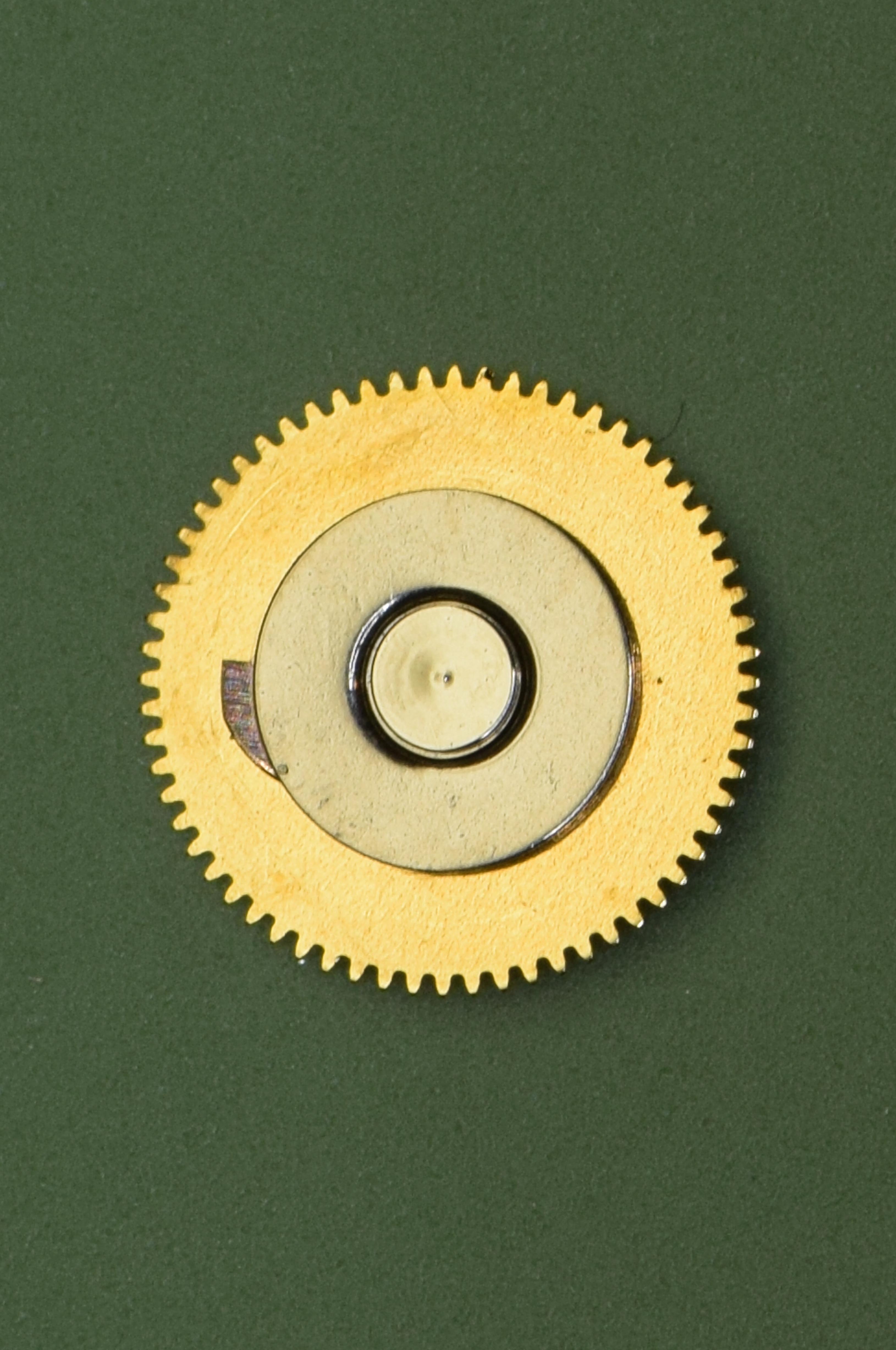
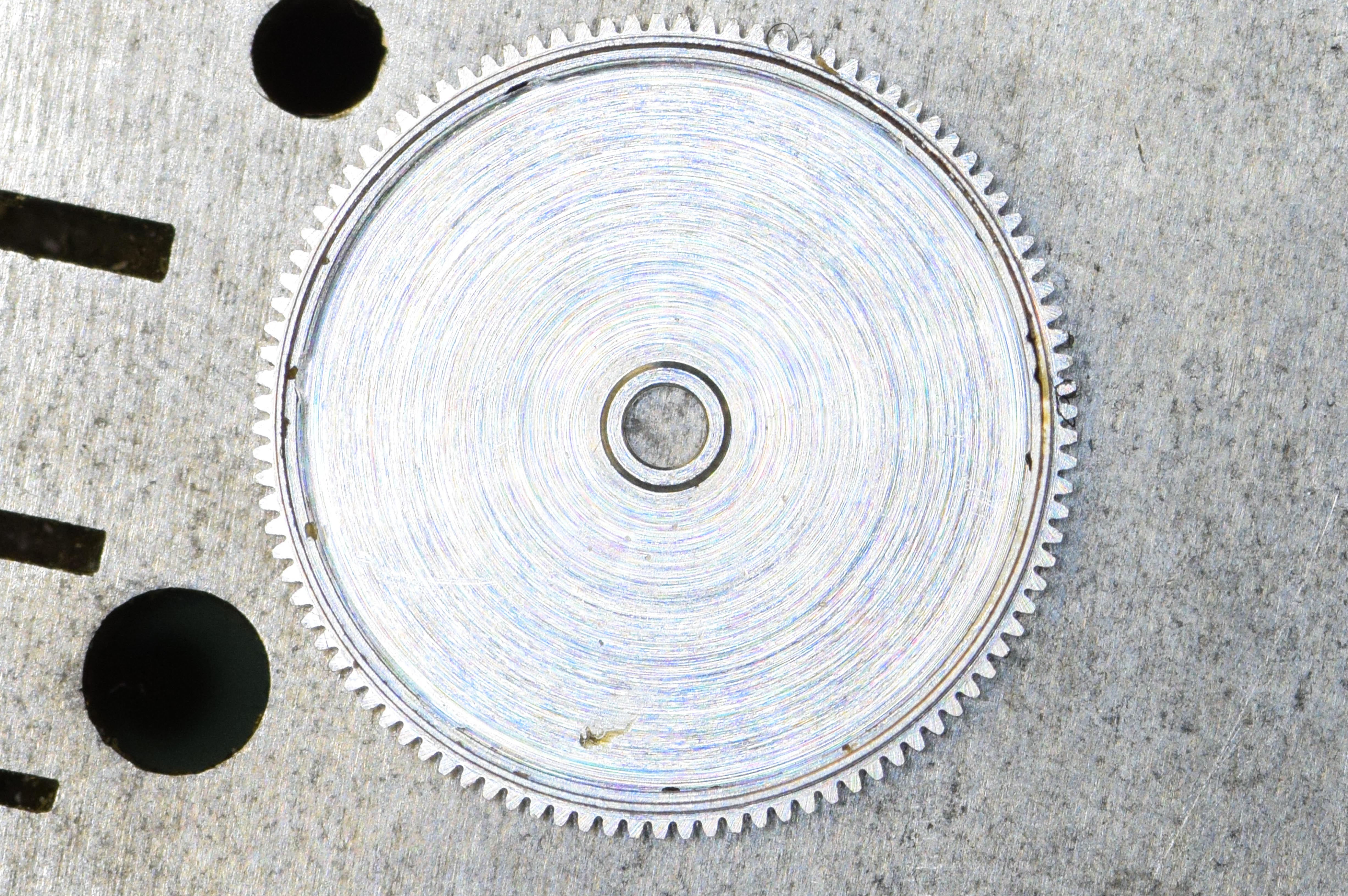
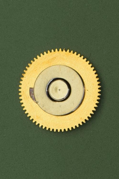
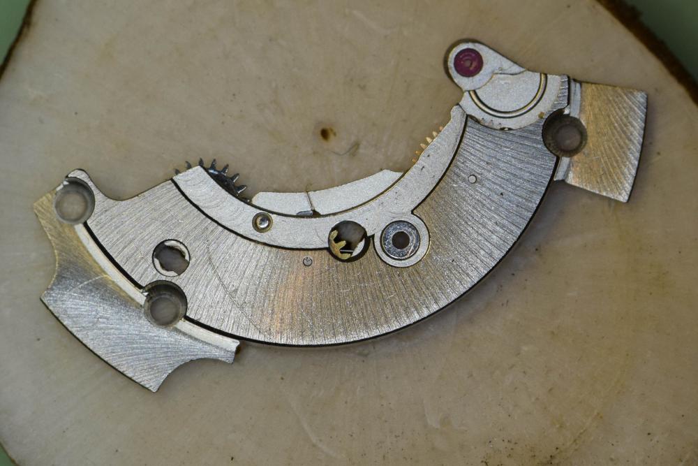
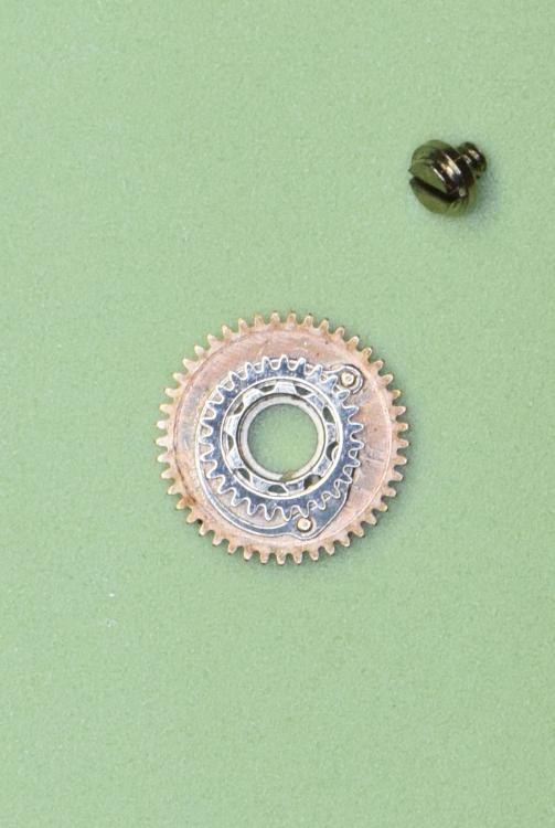
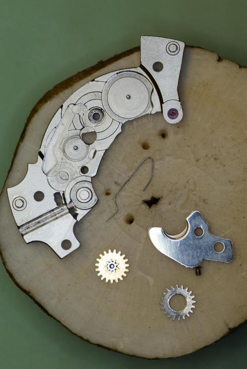
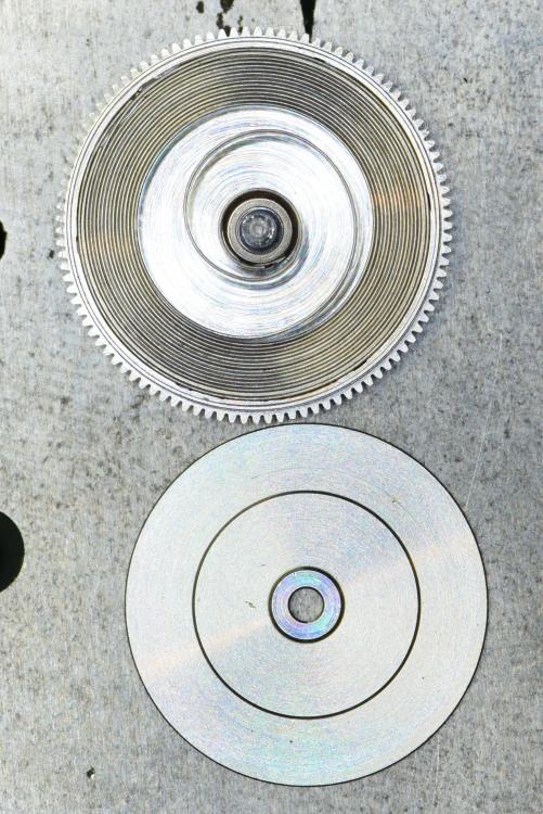
I am in the process of reassembling my 2893-1 - see the previous (part 1) post for disassembly instructions, etc. I will post pics when complete. But I have hit a bit of a snag. I have discovered that the fourth wheel is not seated properly on its post - it is slanted which causes it to wobble in the train. I am struggling a bit to try and find the correct combination of stake and stump to repair this. I have managed to improve it, but not enough. Here is a pic from the disassembly thread that shows the construction. It's the wheel on the bottom. If you zoom in you can see that it is pressed onto the pinion. Curious if others have preferred techniques for dealing with this.