Leaderboard


Popular Content
Showing content with the highest reputation on 04/02/18 in Posts
-
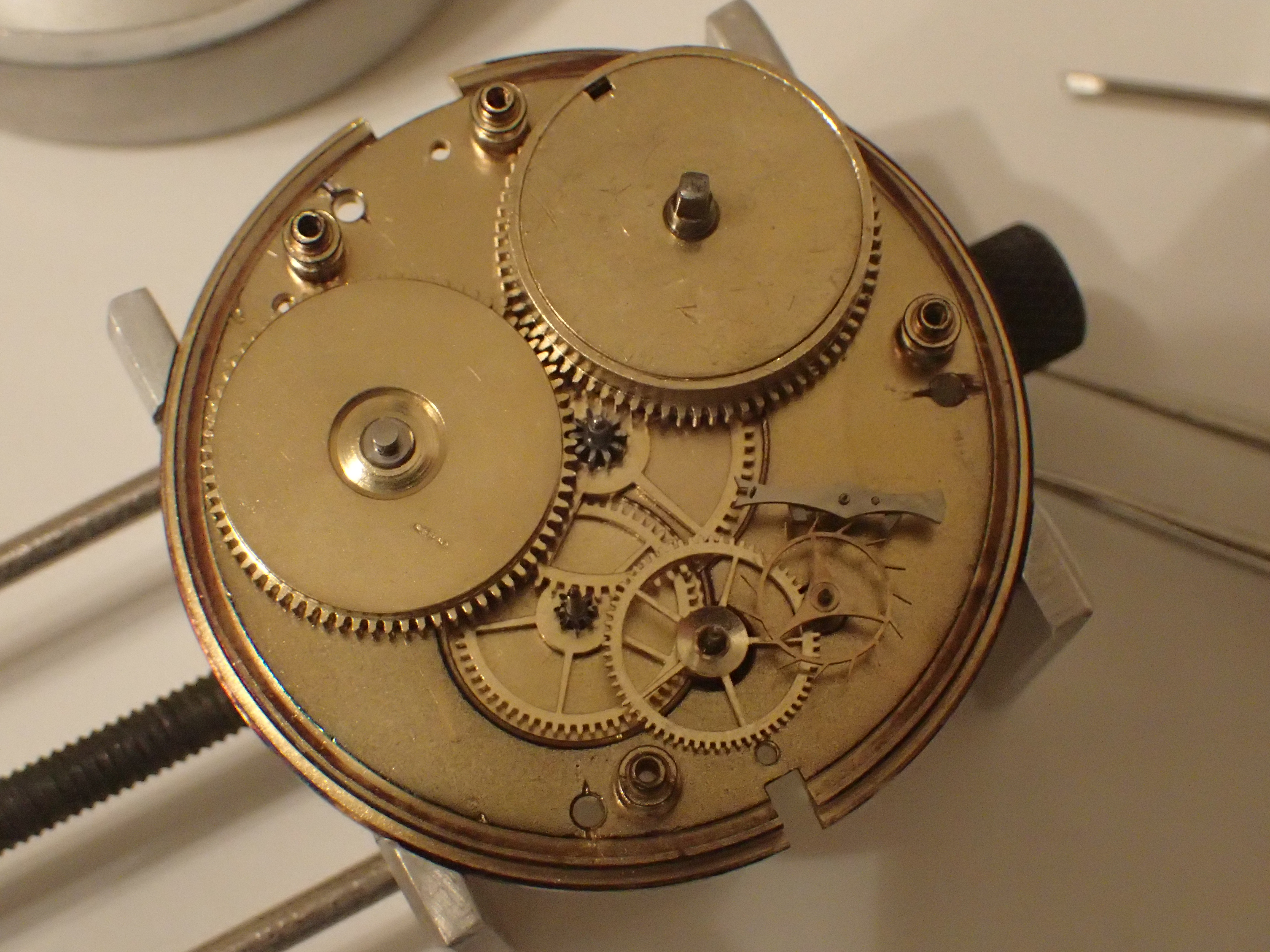
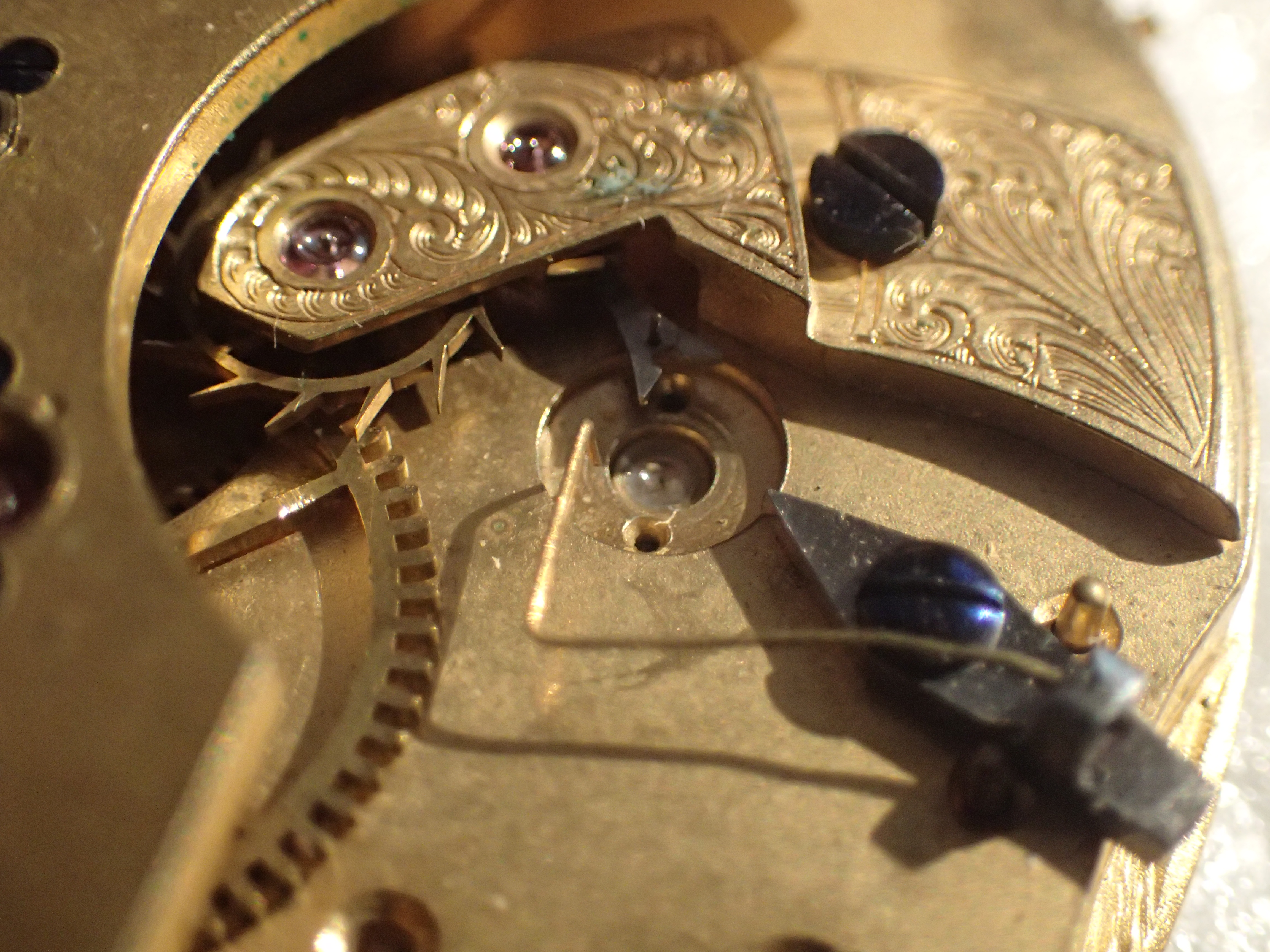
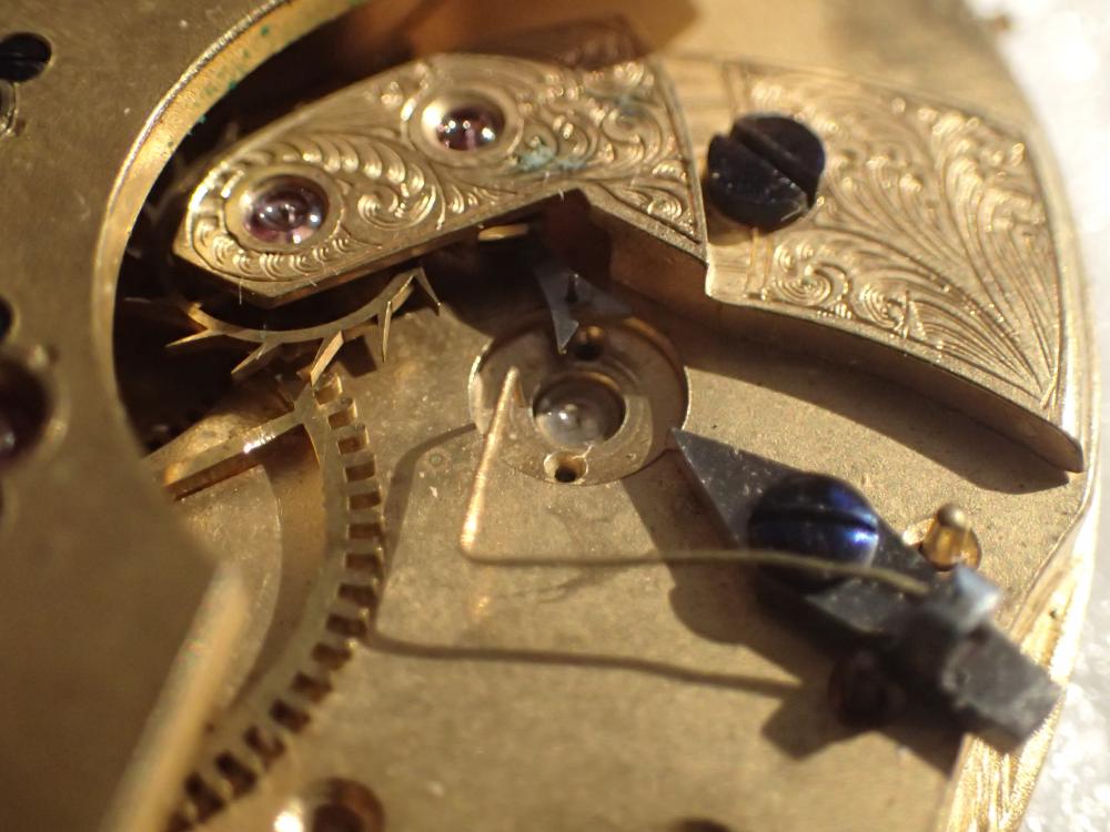
What you have is an indirect centre seconds configuration where the third wheel has an extended staff that comes up through the bridge to the back of the movement. An intermediate centre seconds drive wheel is friction fit onto the extended staff which couples with the centre seconds pinion. you will probably find there is a friction spring sitting on top of the centre seconds pinion to control the inevitable stutter that these design suffer from. This was the how all centre seconds configurations were executed when centre seconds first became a thing. It's a perfectly good way to achieve centre seconds without bu$$ering about too much with the rest of the movement but it has a couple of drawbacks. The stuttering is one of them, the other is it makes the movement quite thick. Anyway, the circular plate that you refer to is not a separate part, it is a thickening of the hub of the intermediate wheel in order to provide enough meat for a competent friction fit on the staff. There is a Presto tool specifically designed for removing these, and I have also seen some very nice pullers that people have made, but a pair of very thin levers or blades usually does the trick if you are careful. And you do have to be careful. The extended staff does not take kindly to anything other than a perfectly vertical lift; cant the wheel off of erpendicular to the staff and the staff will snap. Reinstall using a staking tool to keep everything nice and true.3 points
-
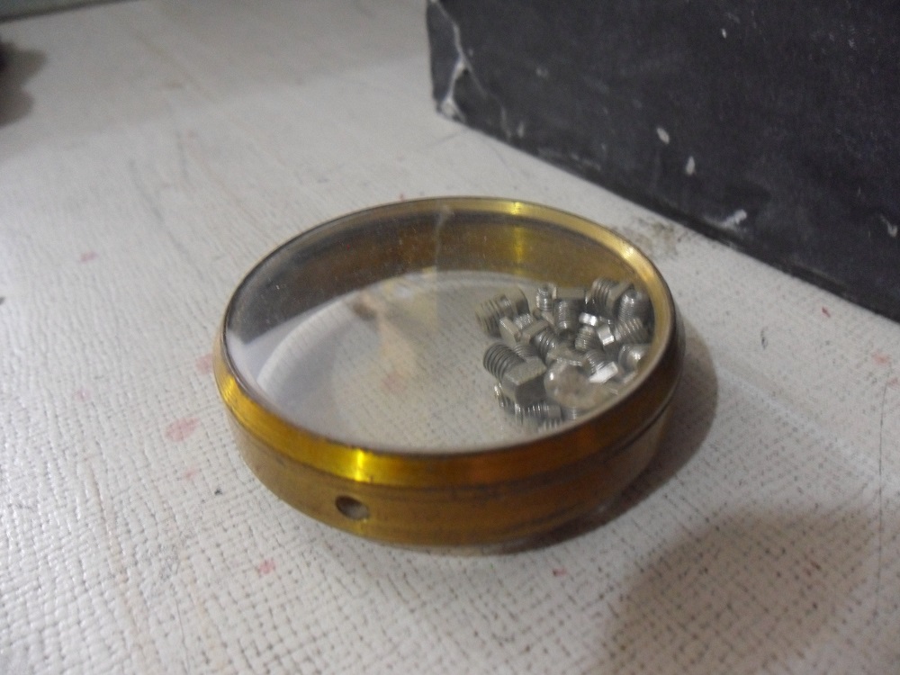
You have the right number of screws and they are all in the right holes except the last two which now seem to be too ferking long. Where is that angle grinder...?1 point
-
There is a really good exploration of the evolution of centre seconds here; http://www.timezone.com/2002/09/24/the-pursuit-of-center-seconds-part-1/1 point
-
Personally I've always called this a sweep wheel. It's frictions on as others have said above it also has an up and a down so pay attention after he remove it. So the tool mentioned above I have another link showing how it's used. It also comes in a different number of fingers apparently there is different arm crossing so you needed tool that correspond to the number of arms you have. Then the tool found At the second link comes in three different sizes color-coded. All you do with this is slide this gently under the wheel rotate and lifts the wheel up. However you lift the wheel up make sure you lifted straight you do not want to bend the post that it's on. http://www.drsjewelry.com/cgi-bin/LTT1.pl?Sub-NSP=Removesandhandpress&Description-NSP=PRESTONo3SWEEPWHEELREMOVERBERGEON&template=1LVC&method=perfect http://www.julesborel.com/products/tools-hand-tools-hand-removers/bergeon-6016-wheel-remover-1-2mm1 point
-
I believe it's a friction fit, and you'd use a presto type remover, such as the bergeon #3 such as this.... https://www.esslinger.com/bergeon-3-presto-sweep-wheel-remover-5-spoke/?gclid=Cj0KCQjwqYfWBRDPARIsABjQRYynR8V4bP1125CP31SBYBzNXme7zIwq55lXmLnkG_NIwPNH_nrUgY0aAkwxEALw_wcB1 point
-
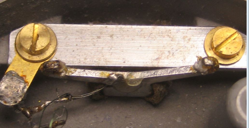
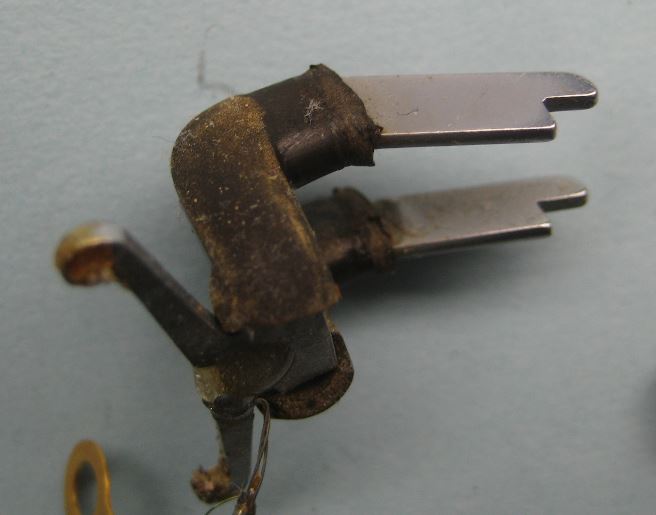
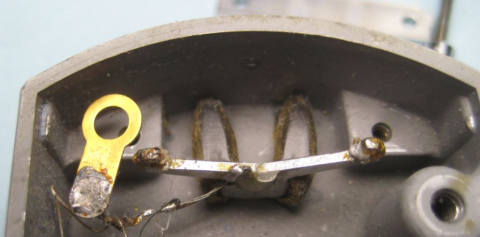
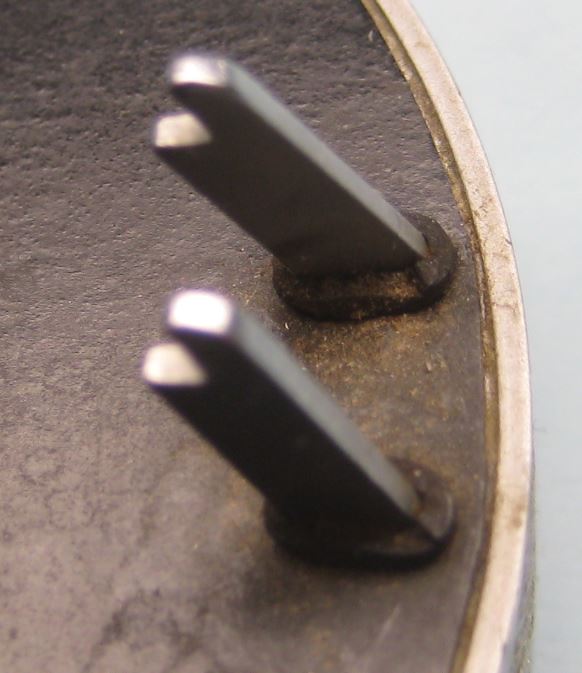
The protruding pin idea is not entirely new. If you look at the commercial microphone that comes with watch timing machines it's basically protruding pins isolated from the base with some form of rubber and the sensor. So I have two links below to where the discussion showed pictures of pickup devices you can see the sensor is isolated with a protrusion. Then images attached of the inside of the pickup disassembled so you can better see how it works. You will notice in my picture though you'll have to refer to the links below as to how the sensor attaches as mine is currently missing. I didn't use enough epoxy and it fell off. So the sensor is inside a metal container grounded and a wire goes to the protruding part so it is also grounded as otherwise it's isolated with the rubber. https://www.watchrepairtalk.com/topic/3002-d-i-y-watch-timing-machine/?page=21 https://www.watchrepairtalk.com/topic/3002-d-i-y-watch-timing-machine/?page=6

 1 point
 -
Those bimorph sensors are the ones I was referring to. I may try just gluing one to an alligator clip to see if that works.1 point
-
That's a real shame. No sound more pleasant that a mechanical movement chime. Pity the movement hasn't a night lever. Is there no way you couldn't thread a piece of wire somewhere to lift the hammer without gumming the works ? You could always buy your daughter a good pair of ear plugs [emoji16] Sent from my SM-T585 using Tapatalk1 point
-
If it just has one hammer its a strike. Bend the hammer away from the gong and bind it with cloth or something that will dull the strike. Some people use a very thick plaster. Not winding it could result in the chiming train fouling and could cause the clock to jam up and stop. Whatever you do don’t remove parts they can easily be lost.1 point
-
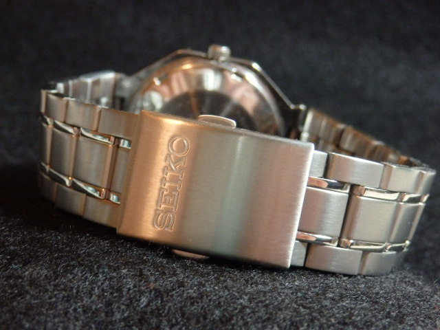
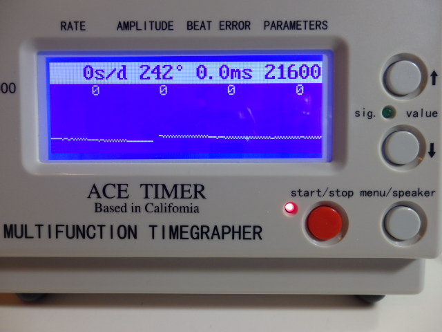
Update # 2 !! I decided to rebuild the movement a little sooner. It turned out ok ! I think the amplitude is pretty good for an entry levelish Seiko. Btw, I'm no expert & this watch has the older Diafix jewel springs on the TWB & they were tricky ! I also got a bracelet so I can wear it now ! Cheers !!
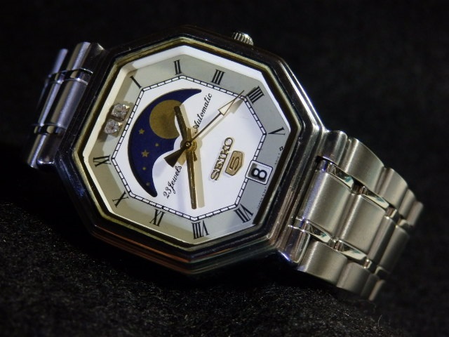
 1 point
 -
As Clockboy said don't wind it..Most all don't mess about with, removing parts makes it worthless, bending the hammer will still clonk if she winds it..Just don't wind it..1 point
-
The correct way to fix this is to broach out the pivot hole, fit a bush then re-establish the hole and oil sink. You will also need to refinish the pivot by filing and burnishing on a jacot tool. You will most likely find guidance on the net by searching for clock pivot bushing. I know there are better links if you look hard, but here is a quick summary http://www.m-p.co.uk/muk/ryoc/doc_page16.shtml I know that some would fit a jewel as it’s quicker and easier, and some would try and punch the edges of the hole to close it up. Neither would be my recommended option!1 point
-
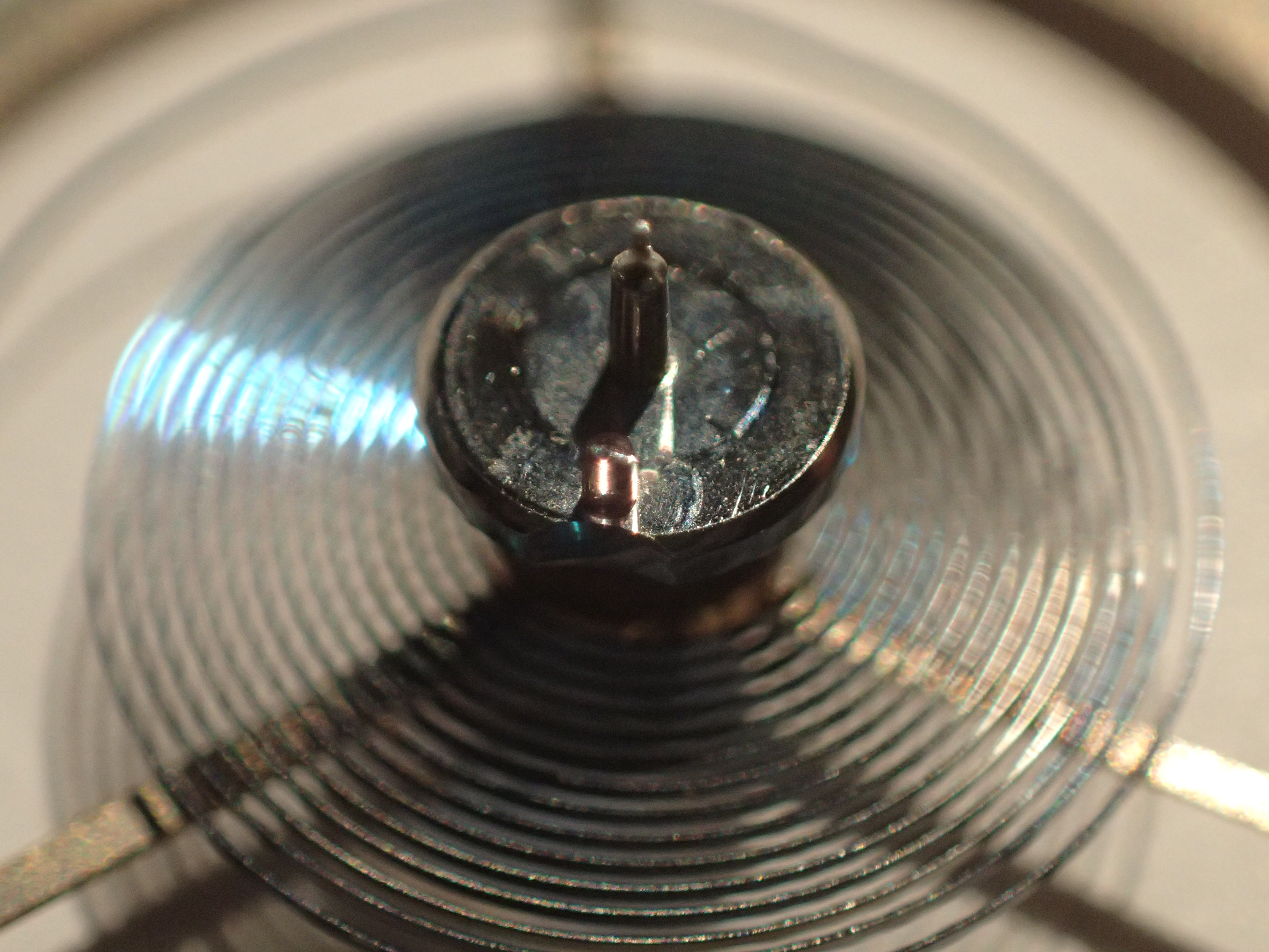
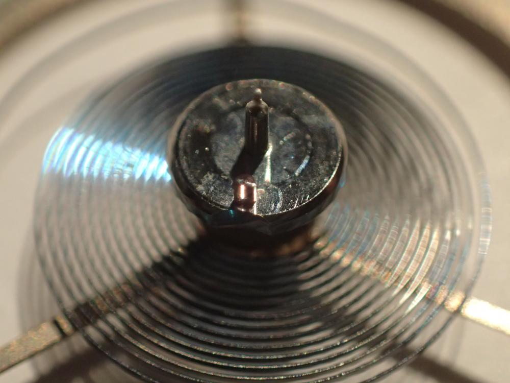
I wouldn’t play around with the timing screws just yet. The best and safest thing is to take the hairspring in and re-pin. You will have to change the position of the hairspring on the balance to get it in beat but that is not difficult.1 point
-
I've got a Olympus TG-4. It's got a "microscope" mode that allows really close shots. They seem very good. I've not set up lighting on any of these - they are done either with background room lighting or a Ikea bendy led desk lamp. I'm also hand holding the camera so that add shake. With a stand and proper lighting you could get some cracking shots.

 1 point
 -
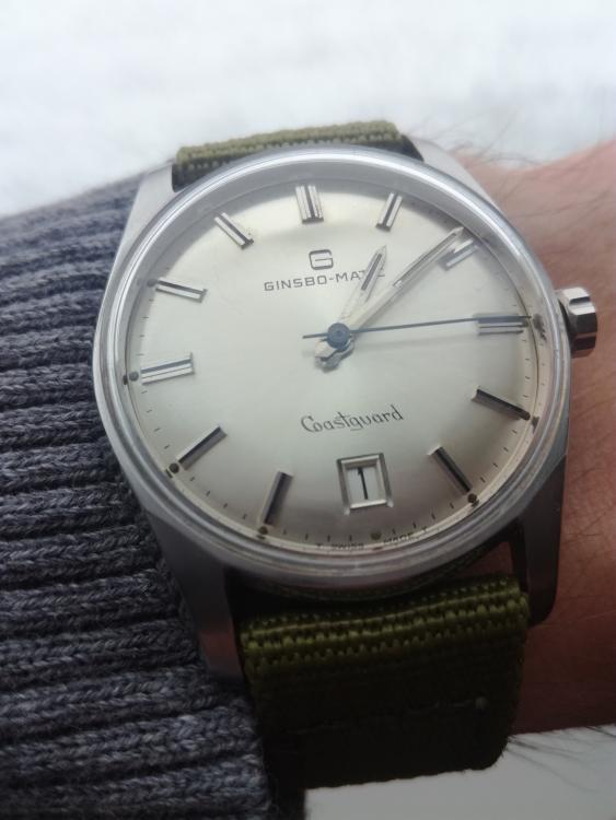
This one makes me want to buy 19mm straps! Sadly I have zero, so this Seiko 5 strap will have to do for now. ETA 2472 (wish it had proper quickset).
 1 point
 -
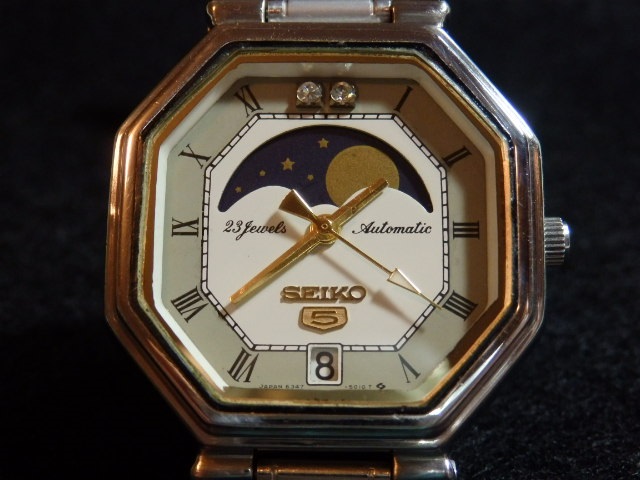
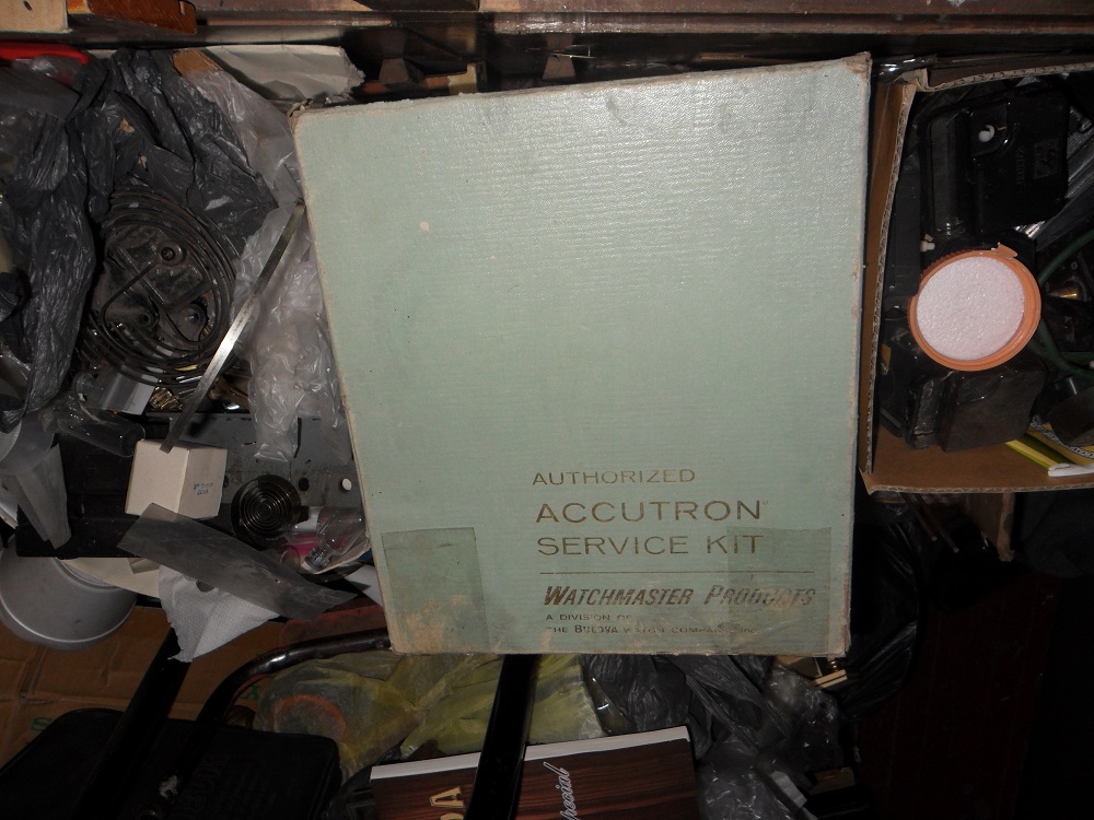
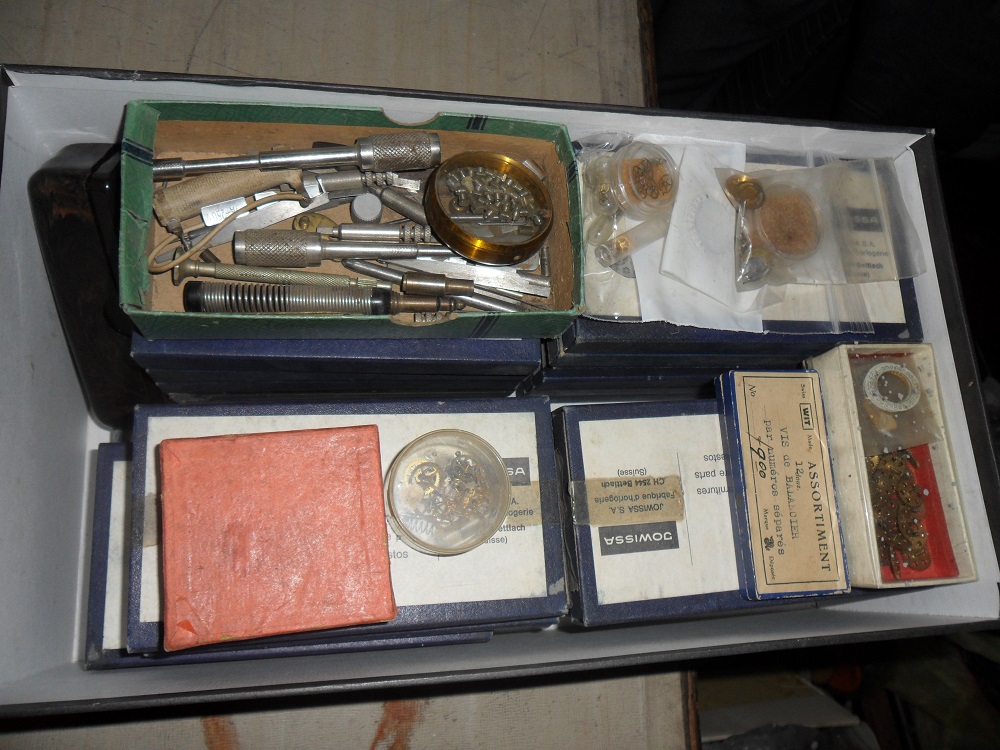
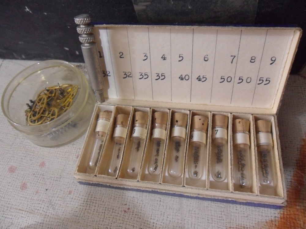
Hello Again. Is it correct if I define these as "Watchporn"? Hope you like it... More soon. Thank you very much for watching.
 1 point
 -
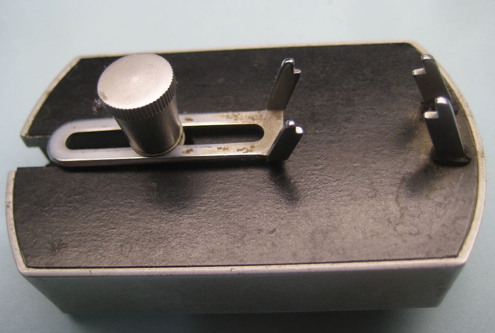
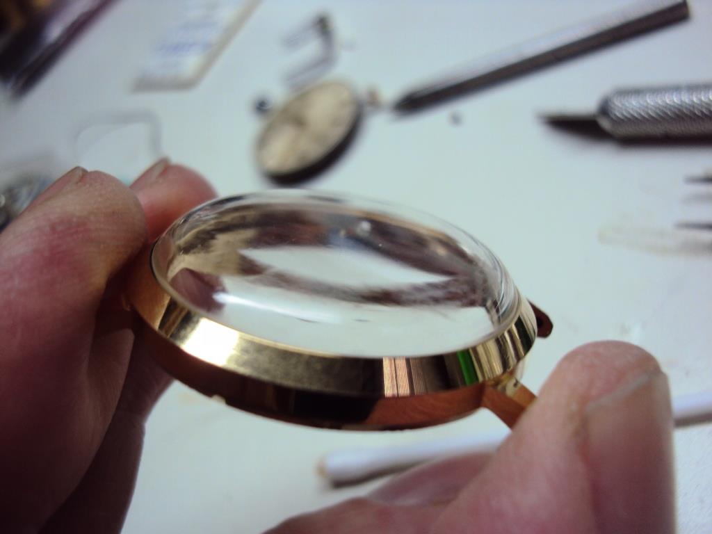
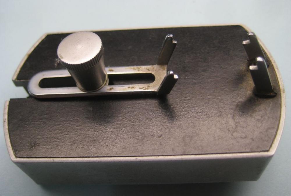
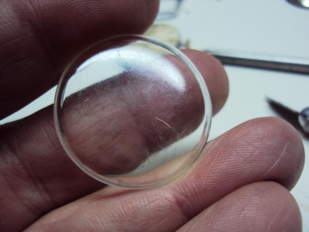
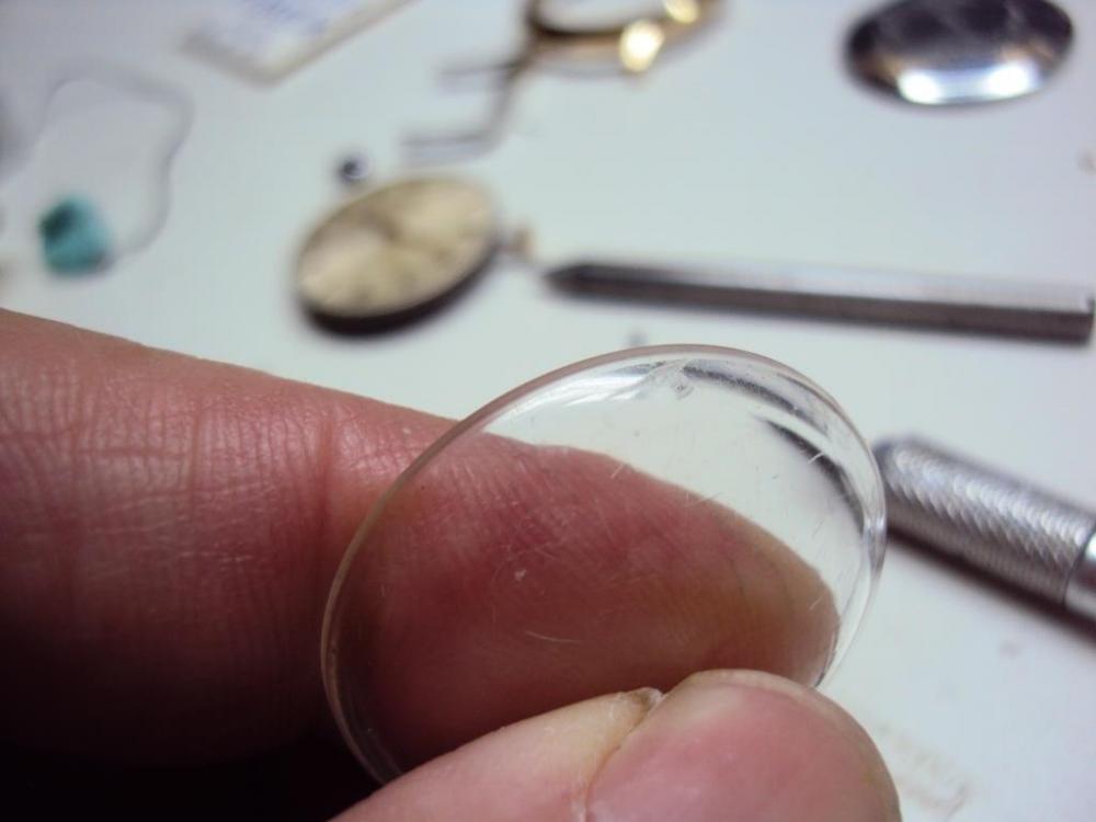
That base actually holds the crystal in place and the metal sides space the compressor up slightly to leave enough plastic at the bottom of the crystal to insert into a case. Am I correct?1 point
-
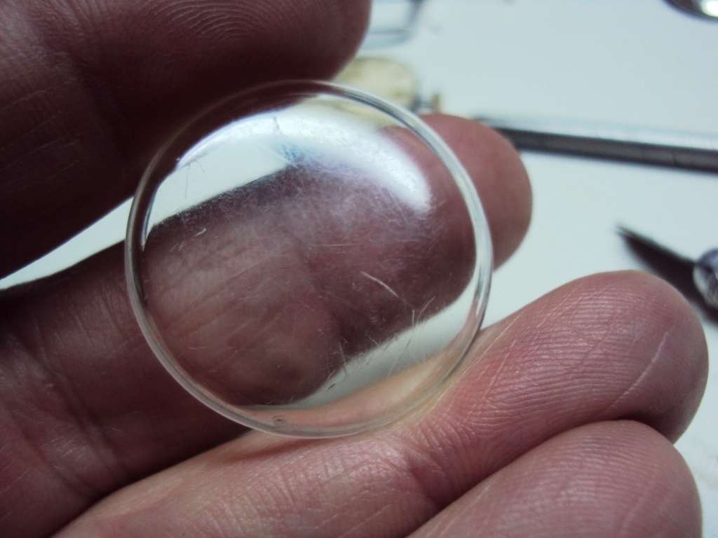
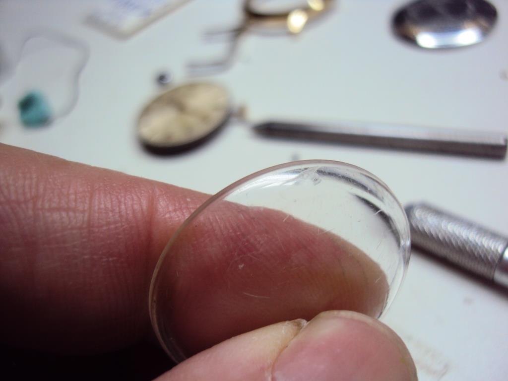
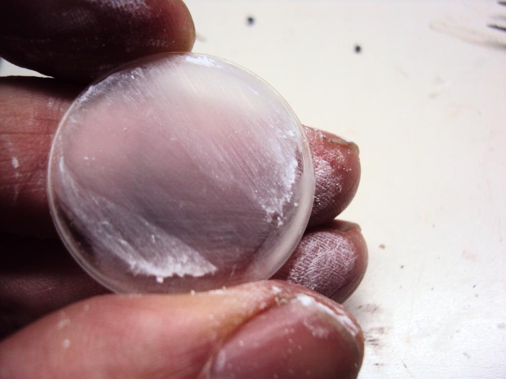
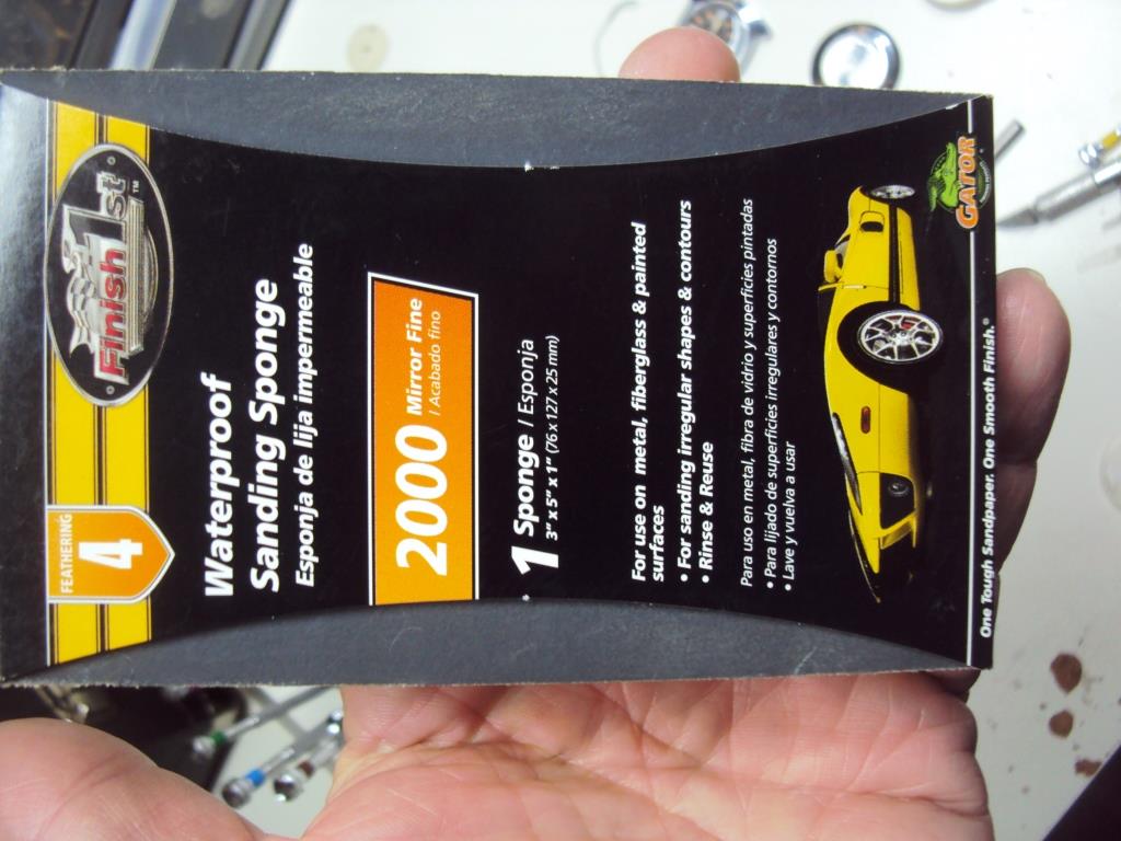
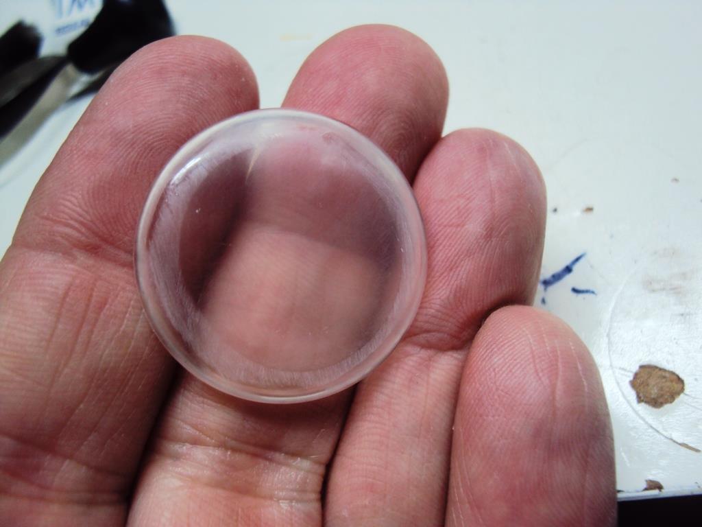
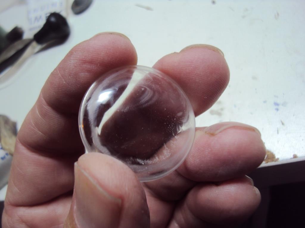
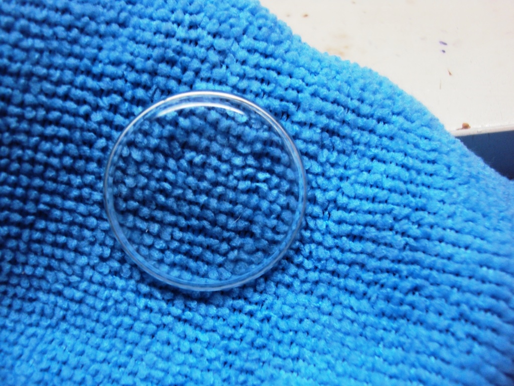
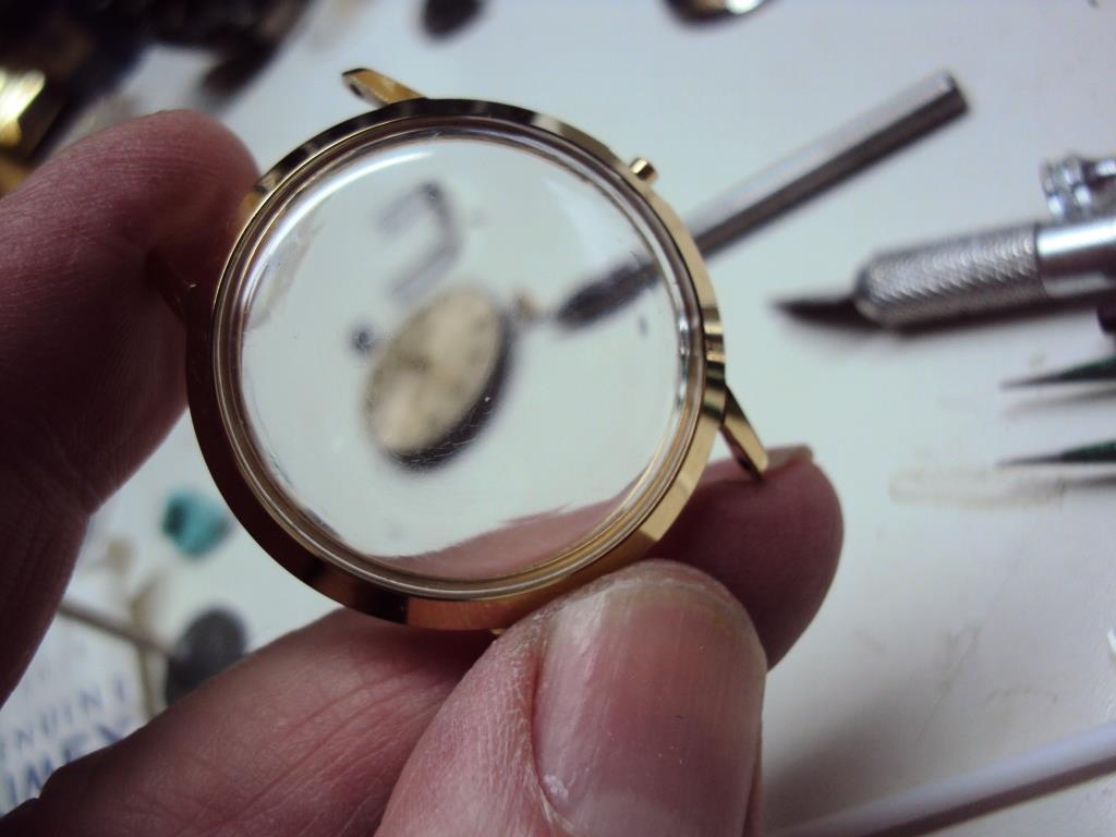
Here is the process in pictures - This one comes from a 1964 Viscount (Auto Timex)


 1 point