Leaderboard


Popular Content
Showing content with the highest reputation on 04/30/17 in all areas
-
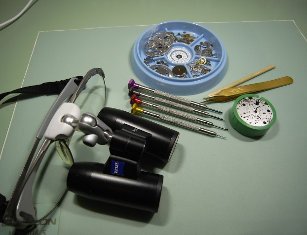
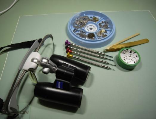
Well after a year of building my skills and discovering good tools vs bad, I finally have a workspace that is comfortable and large enough to lay out all of my tools properly. A lot of advice I gleaned from Mark and this board so thanks to all Sent from my iPhone using Tapatalk2 points
-
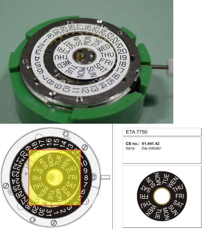
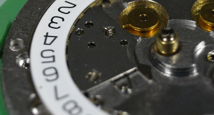
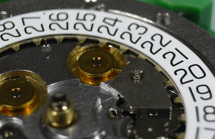
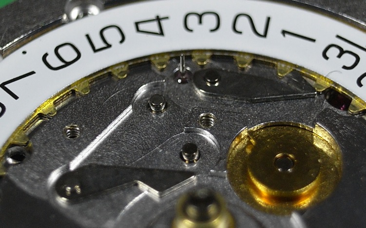
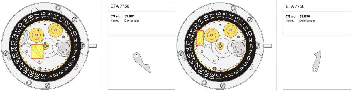
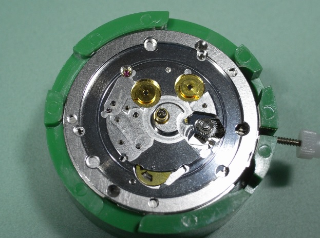
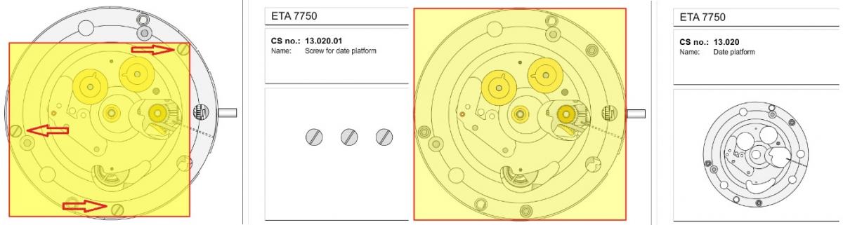
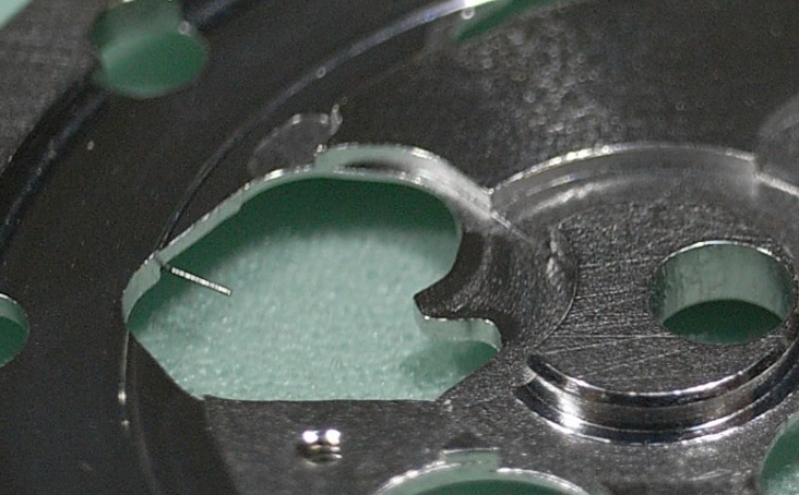
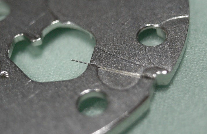
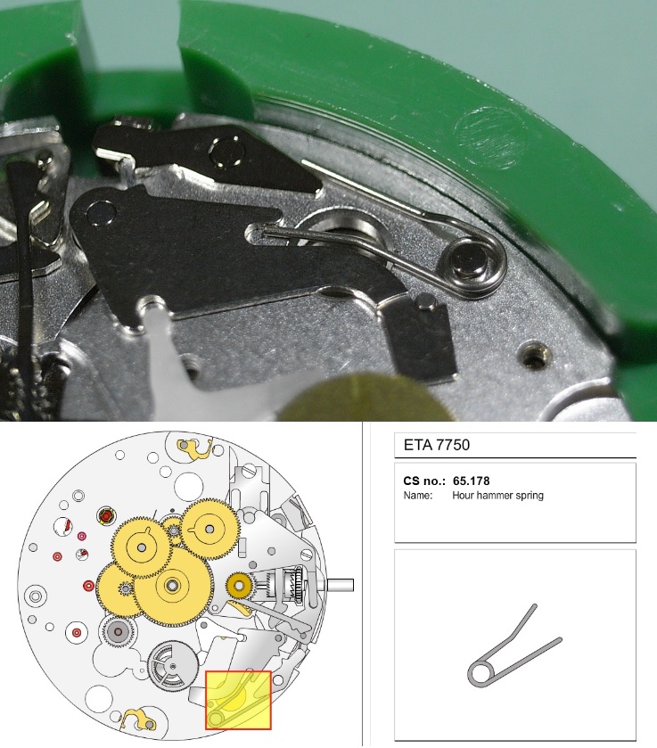
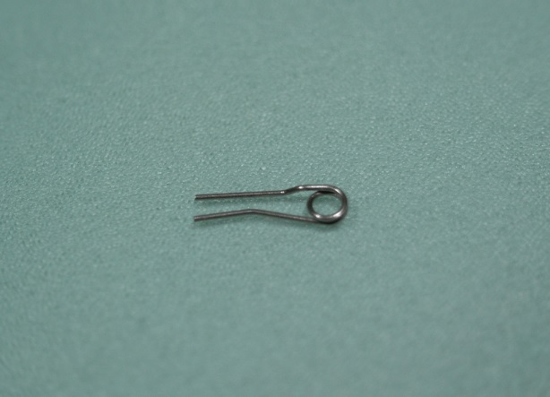
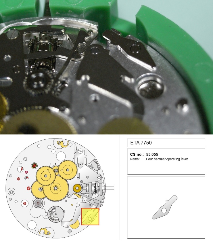
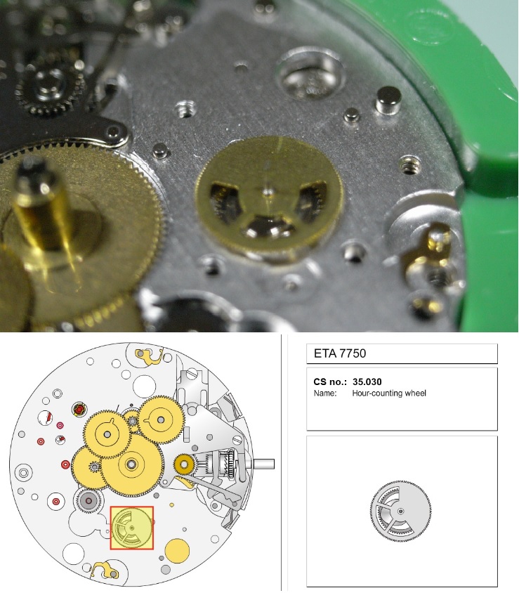
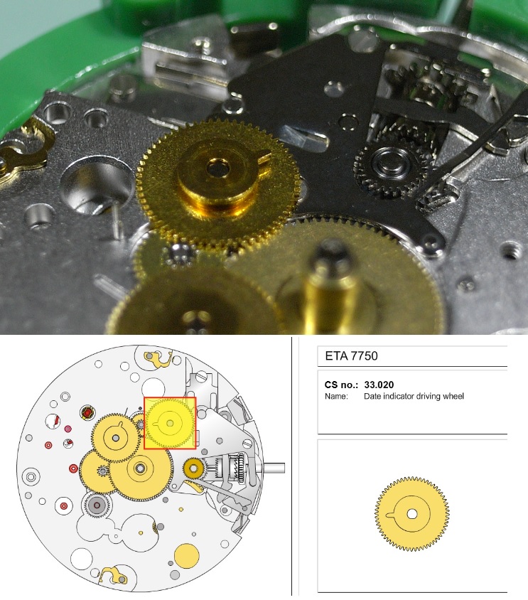
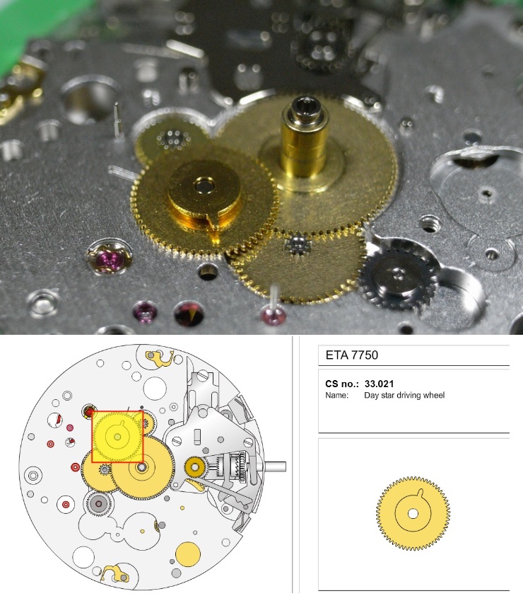
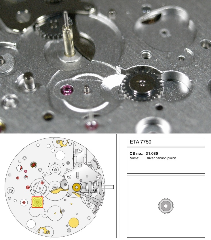
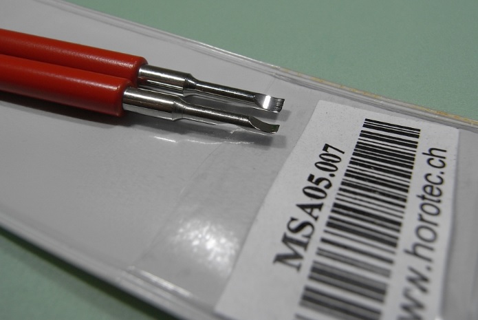
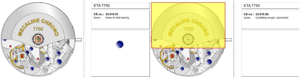
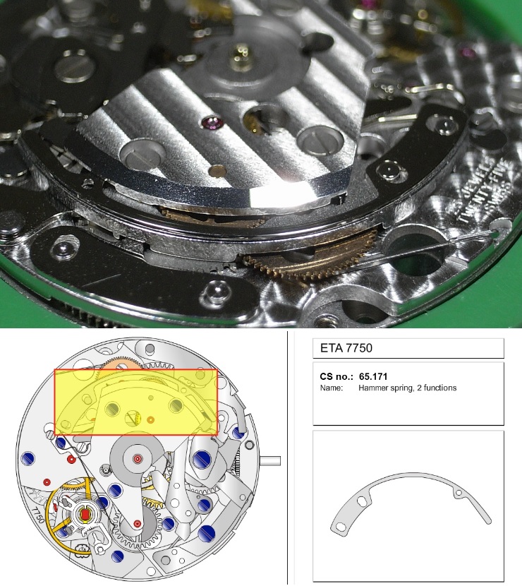
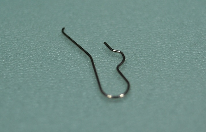
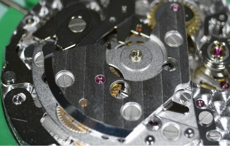
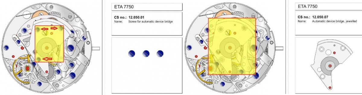
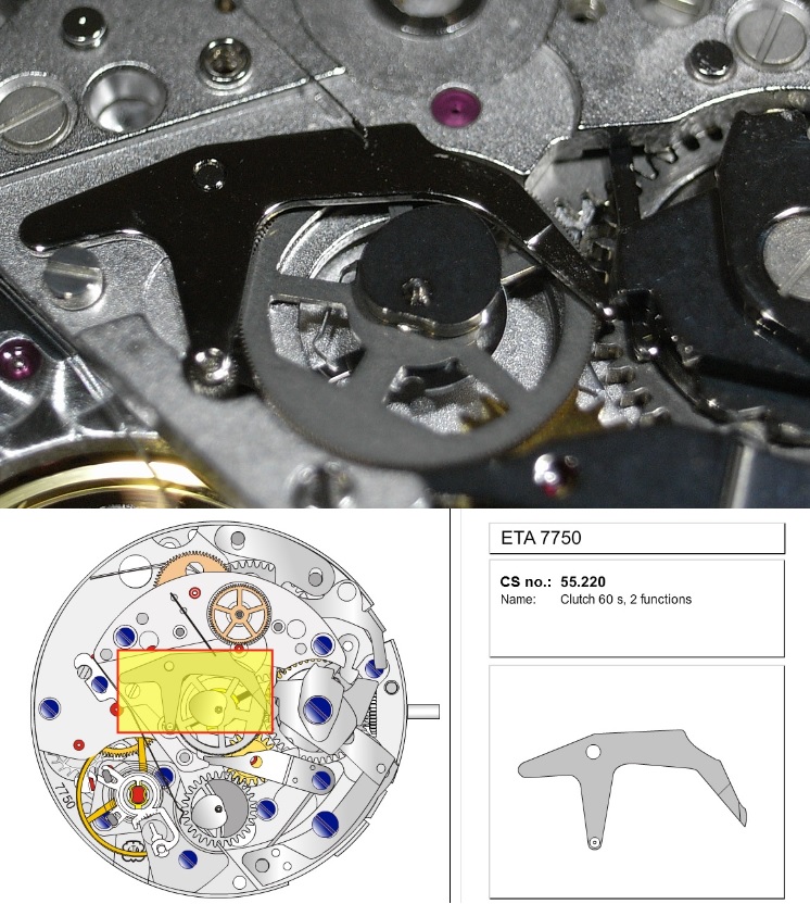
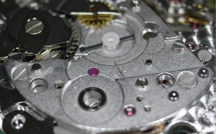
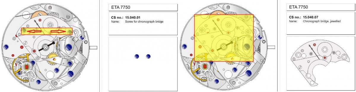
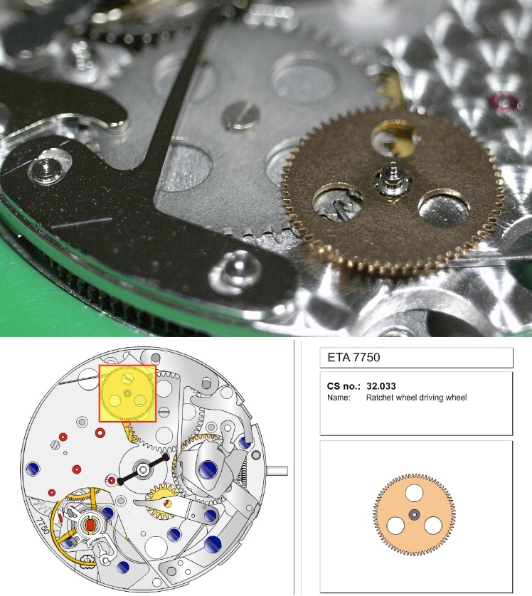
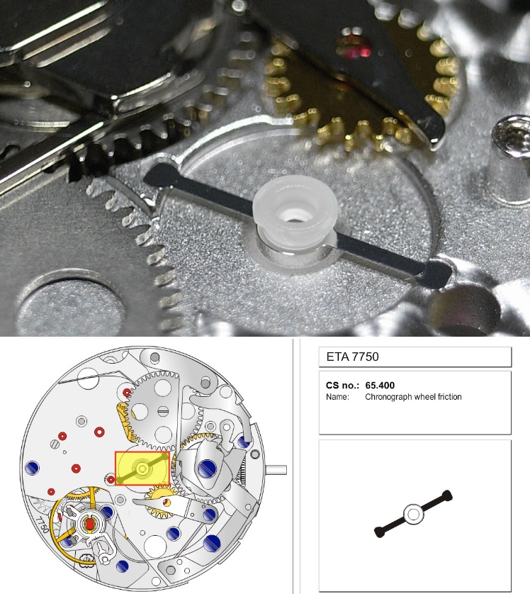
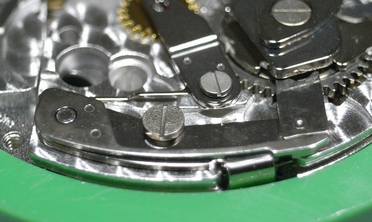
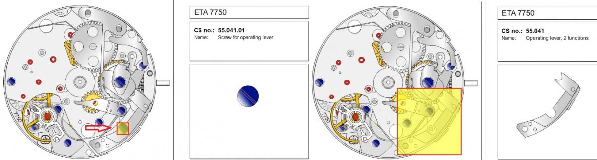
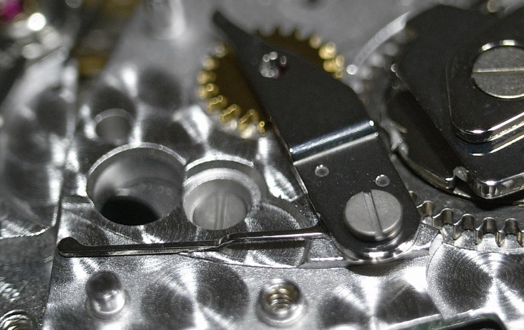
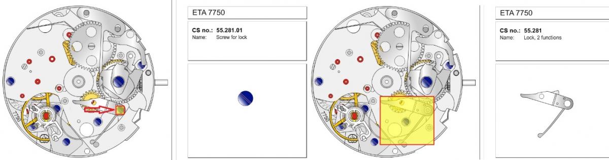
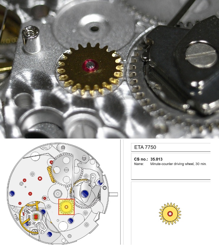
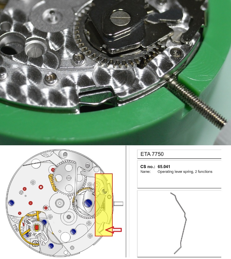
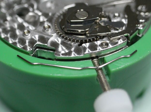
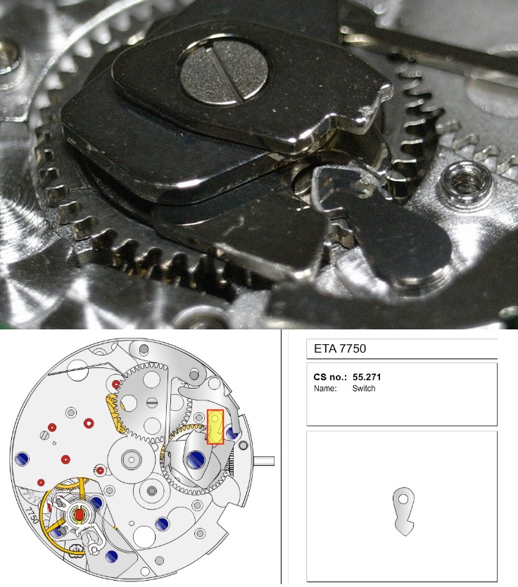
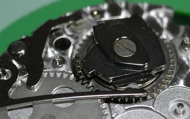
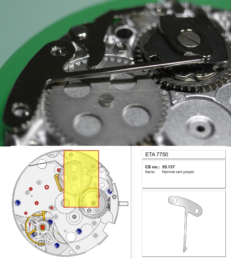
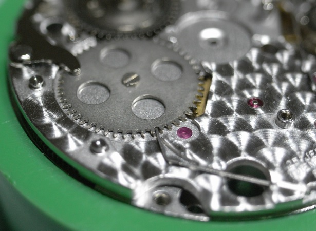
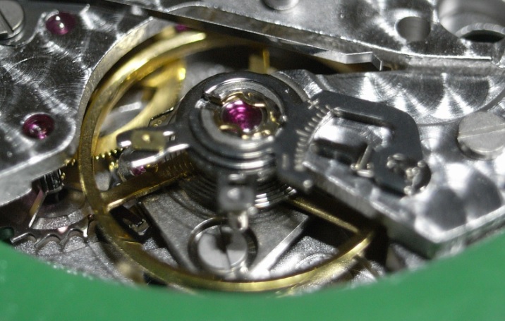
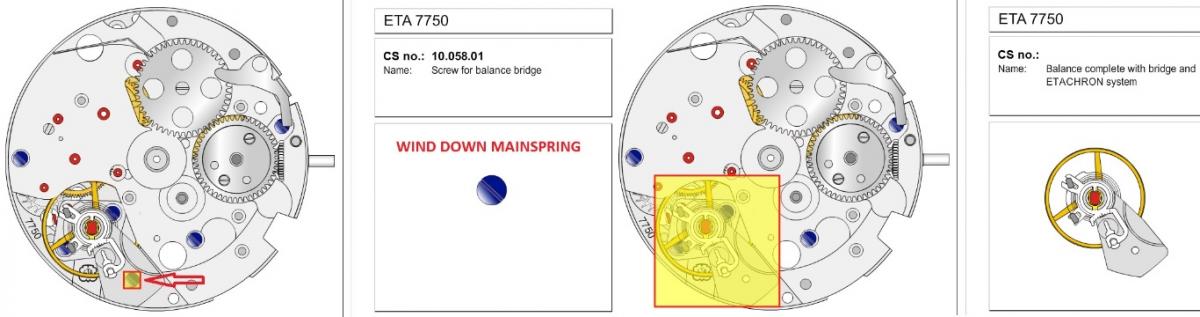
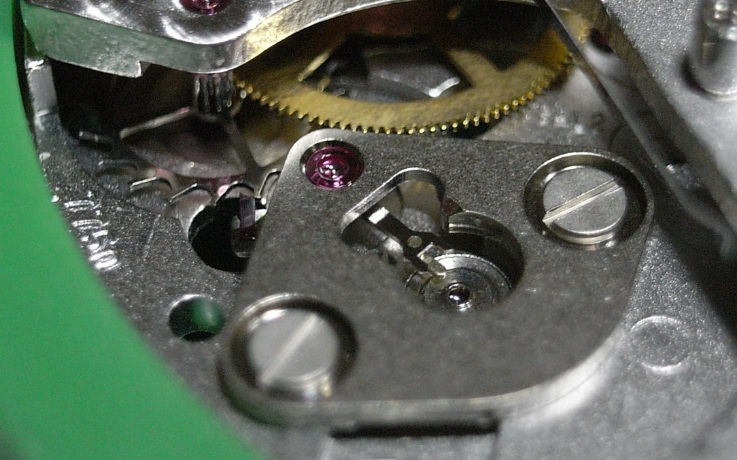
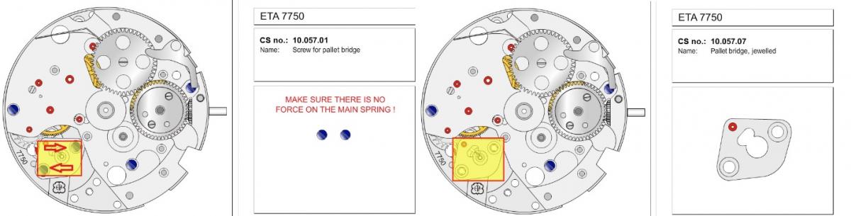
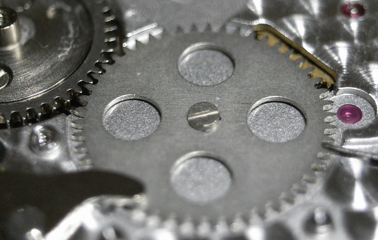
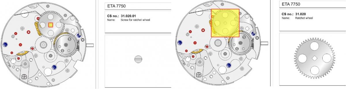
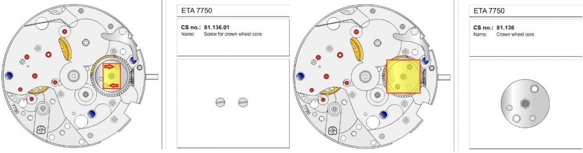
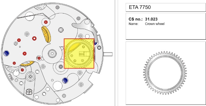
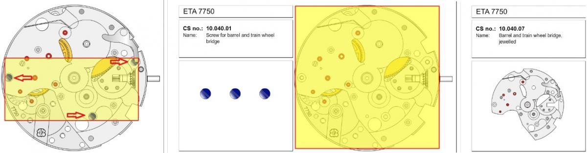
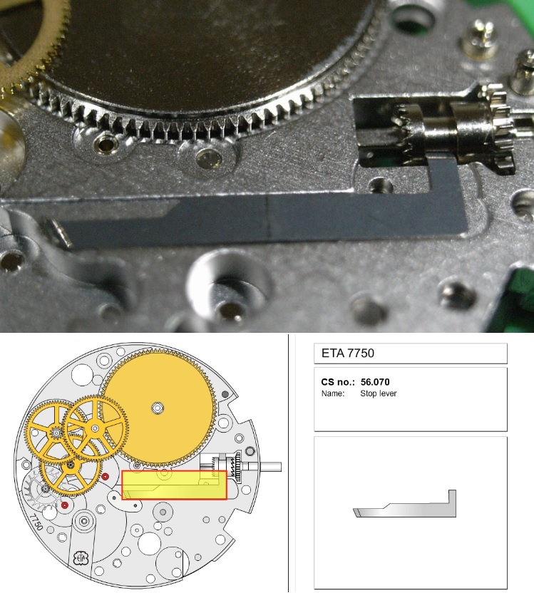
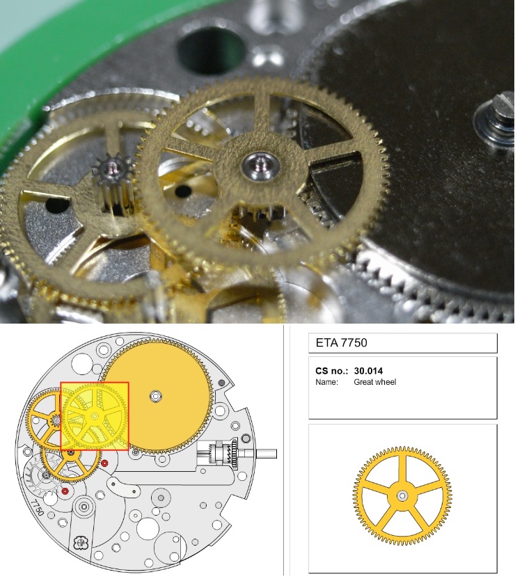
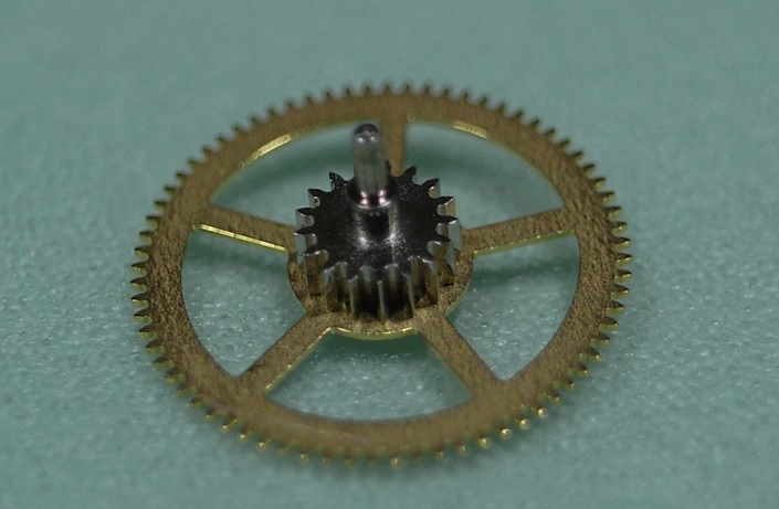
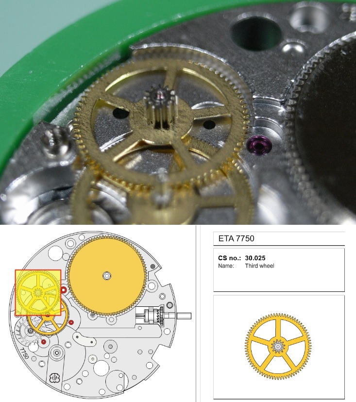
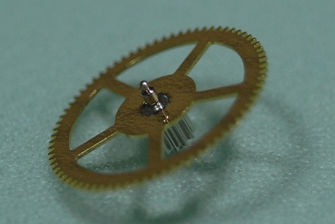
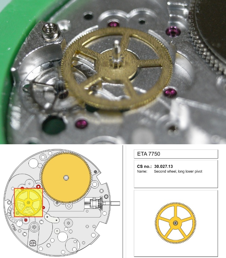
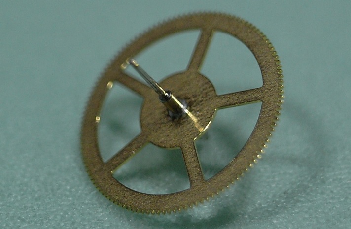
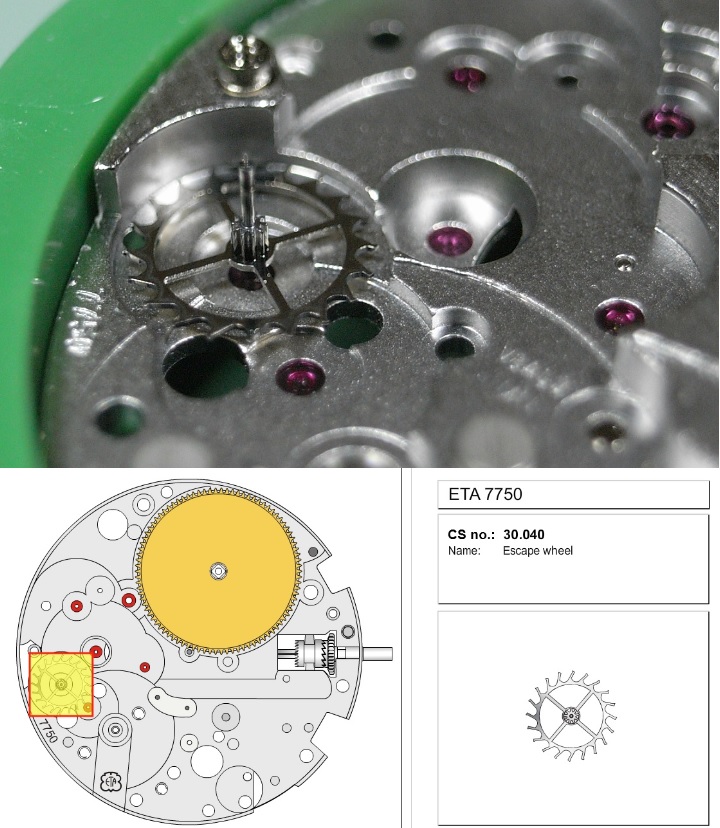
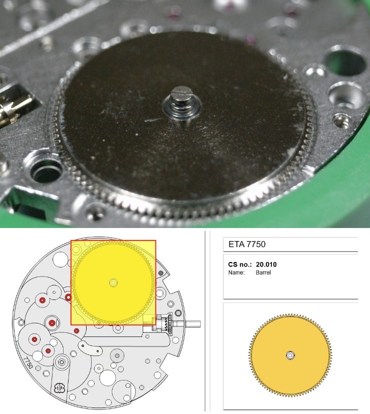
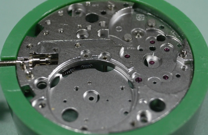
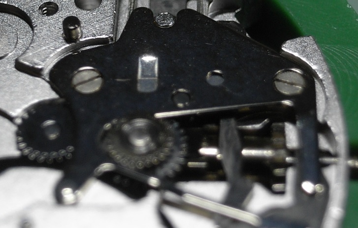
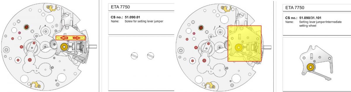
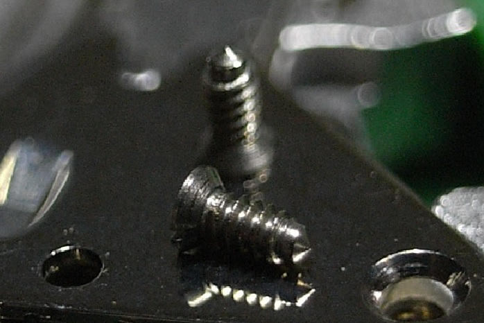
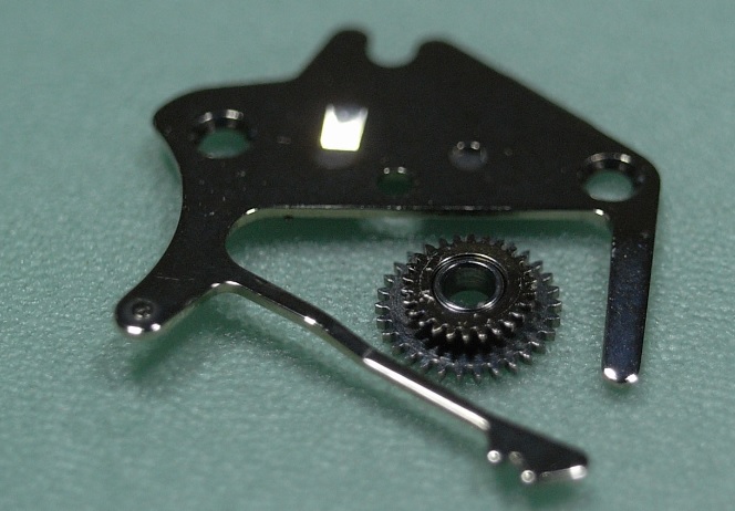
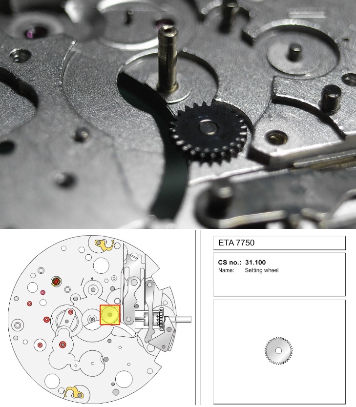
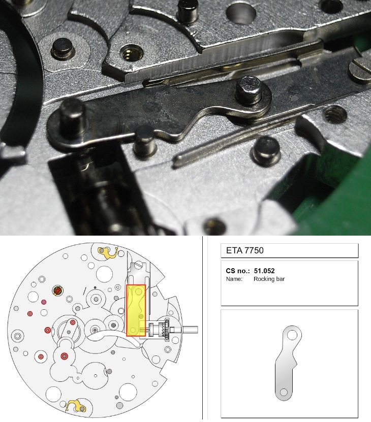
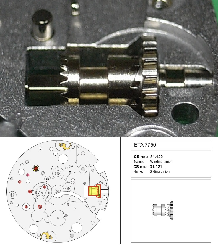
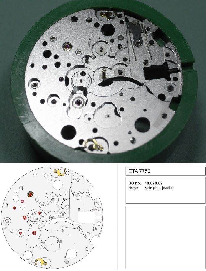
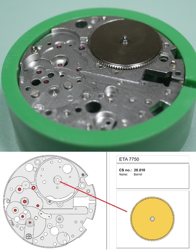
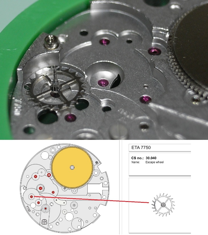
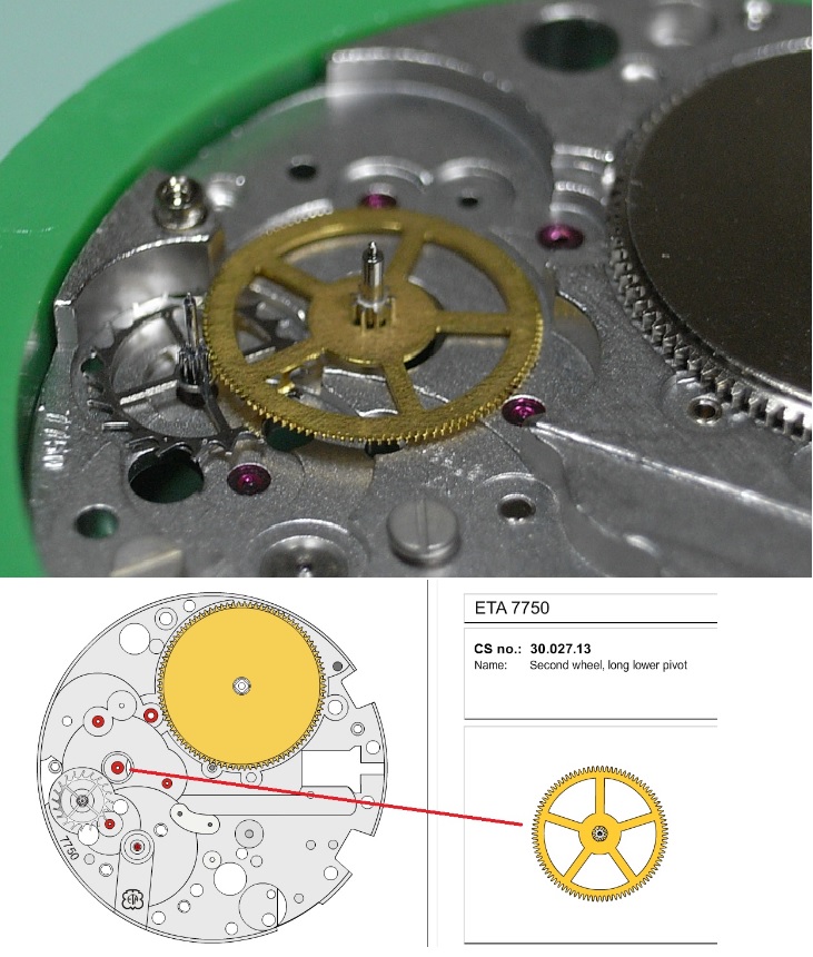
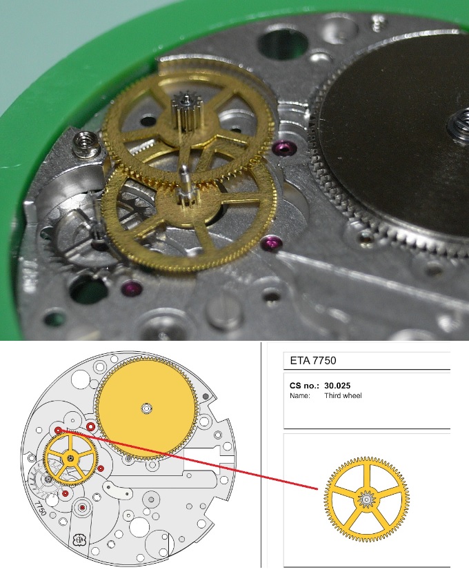
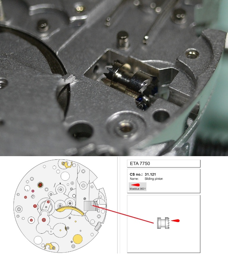
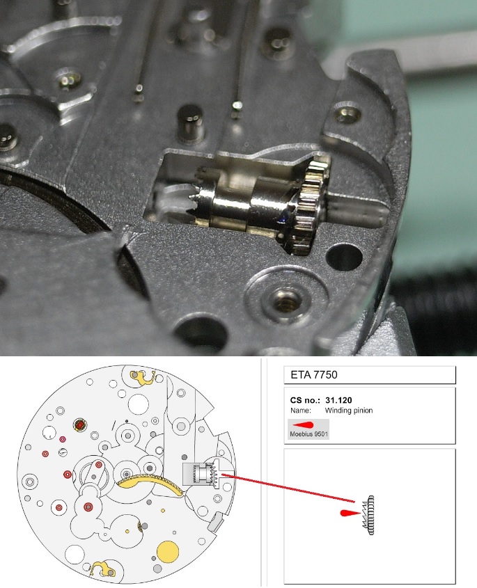
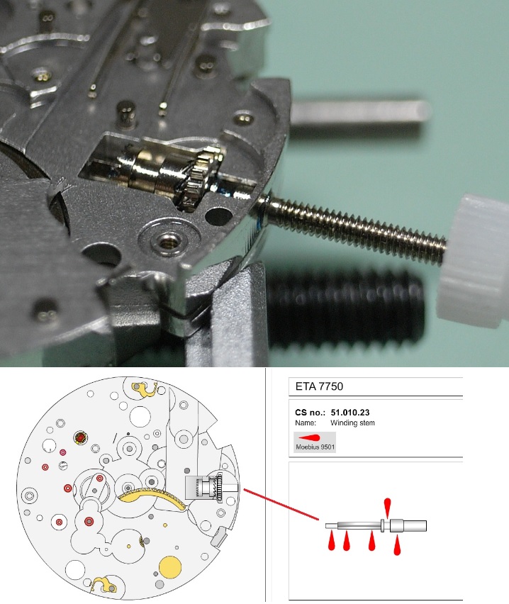
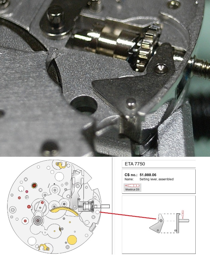
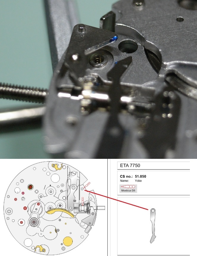
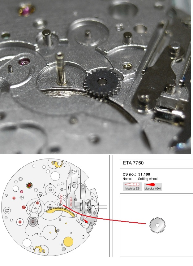
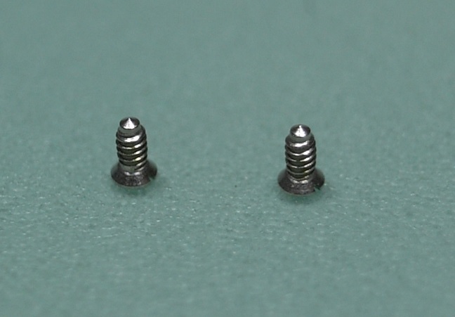
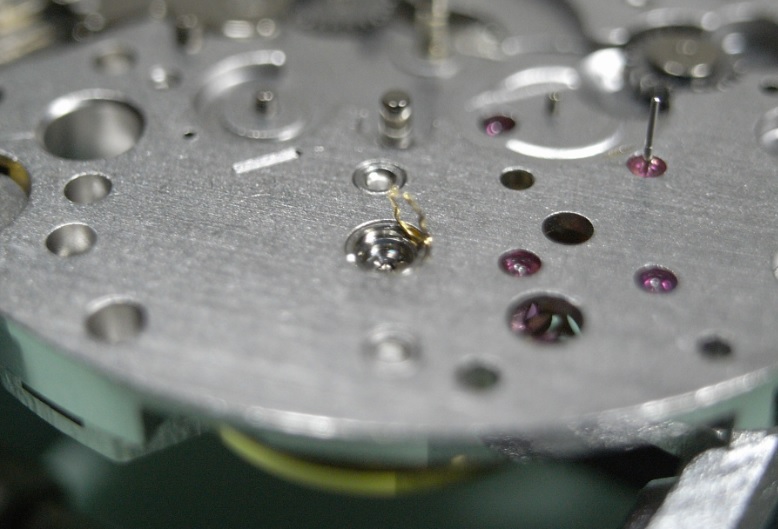
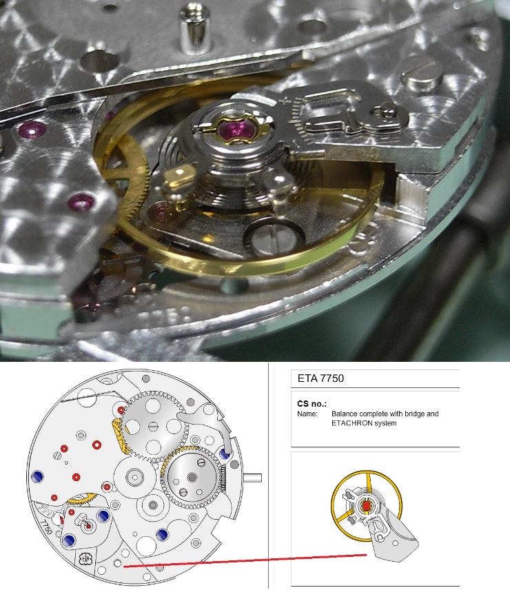
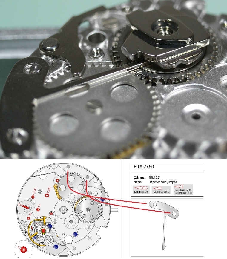
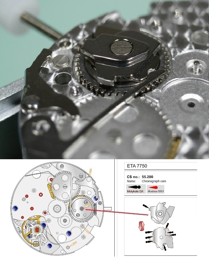
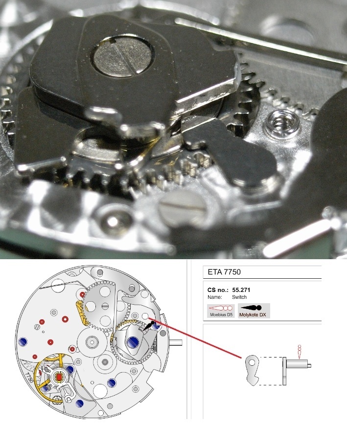
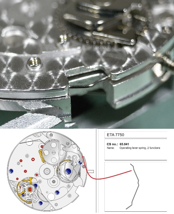
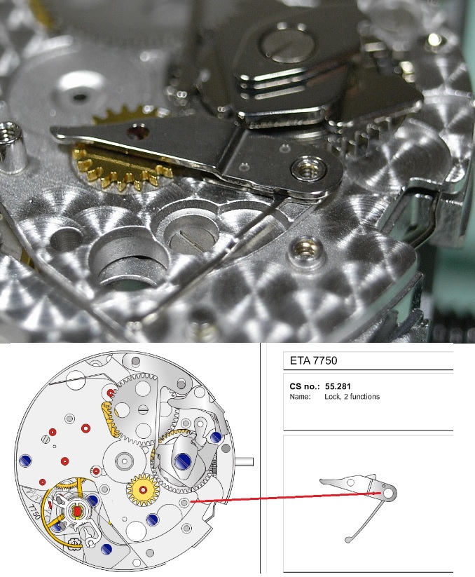
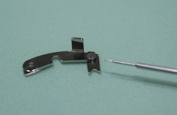
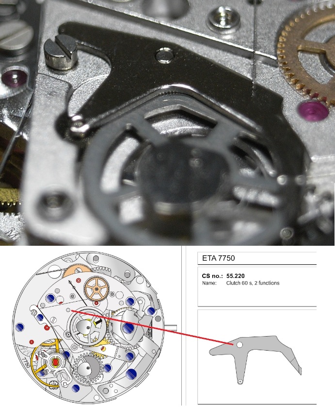
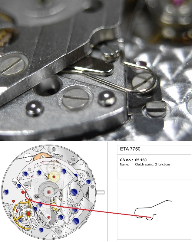
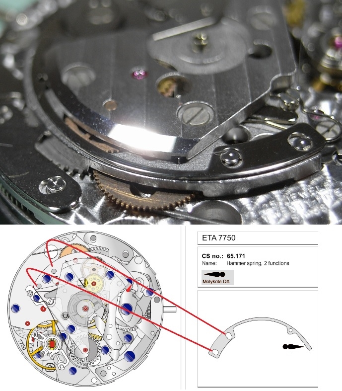
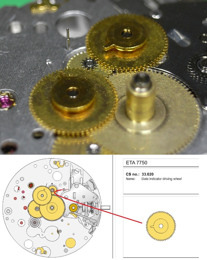
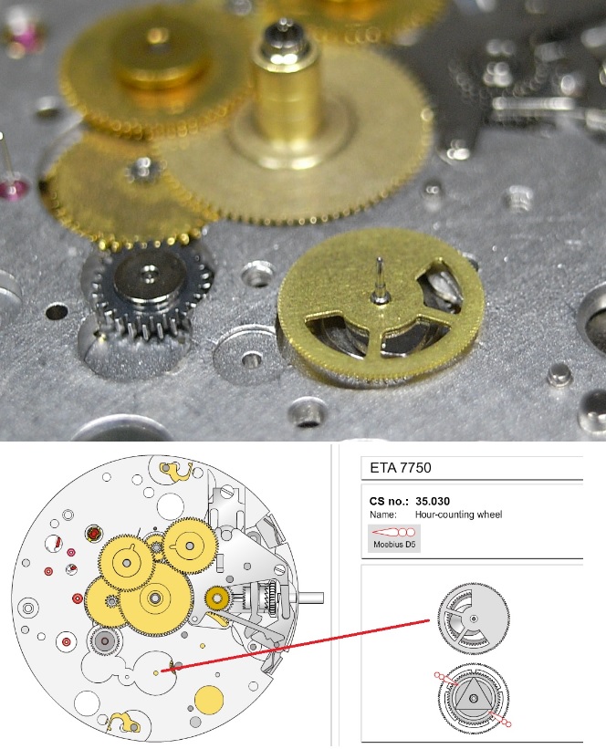
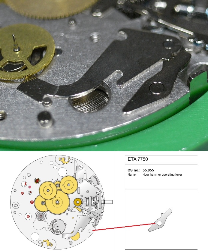
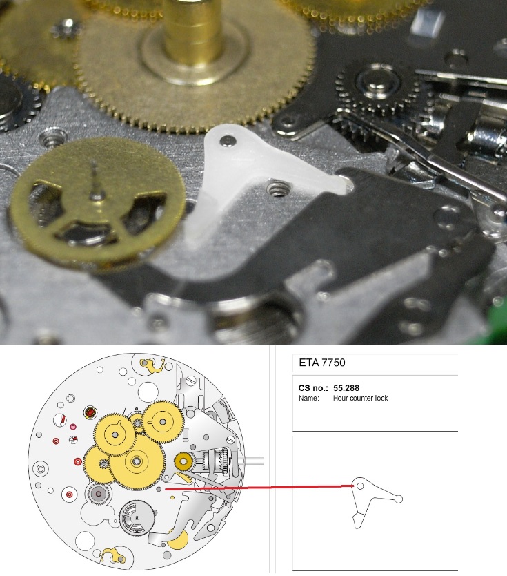
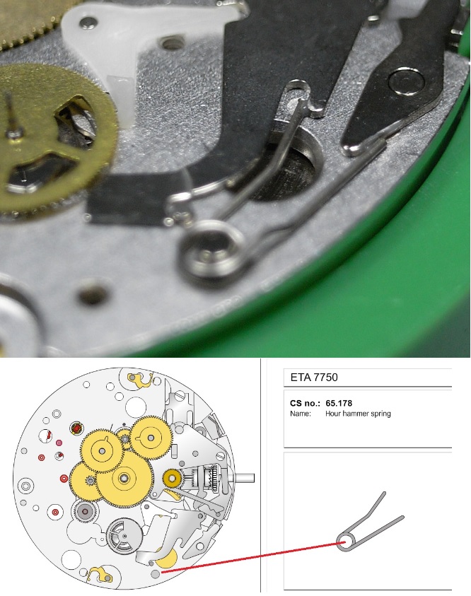
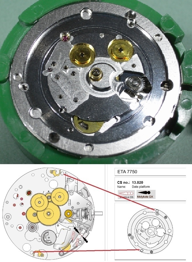
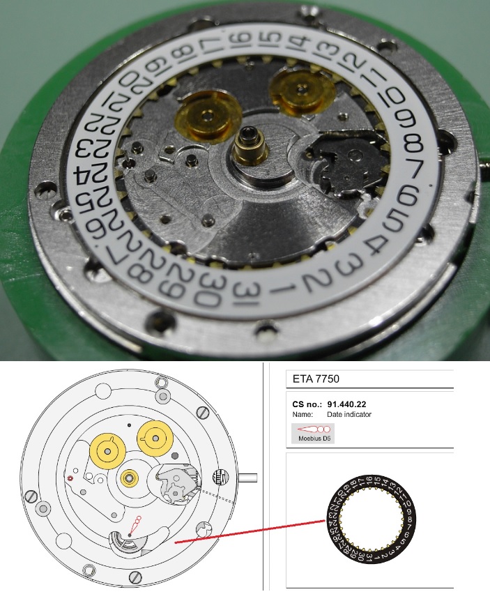
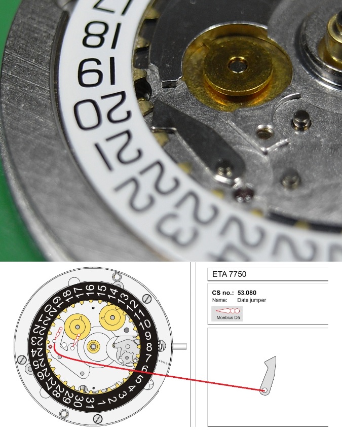
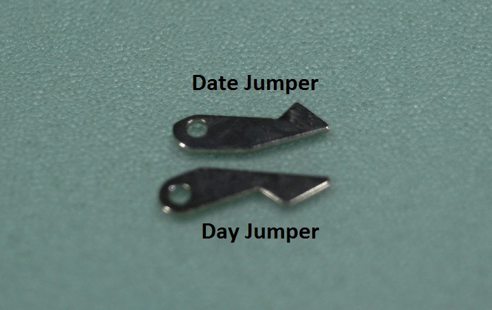
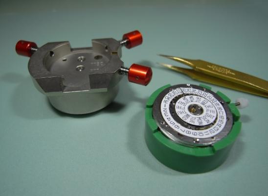
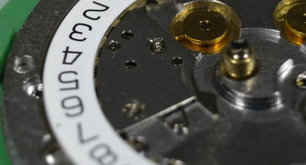
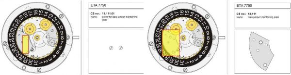
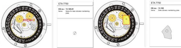
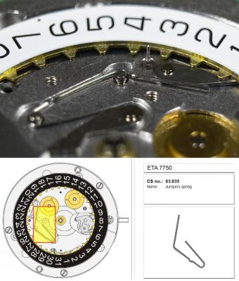
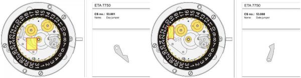
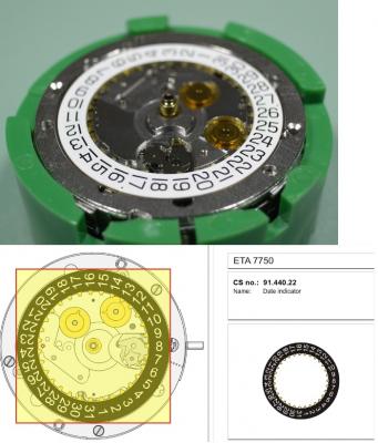
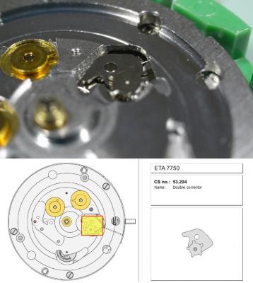
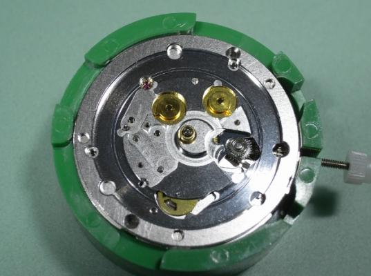
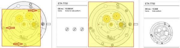
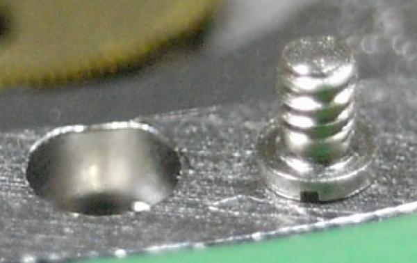
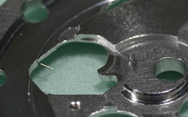
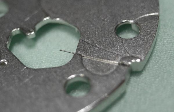
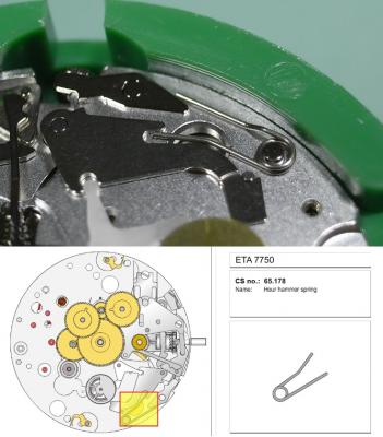
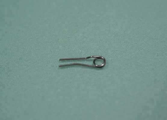
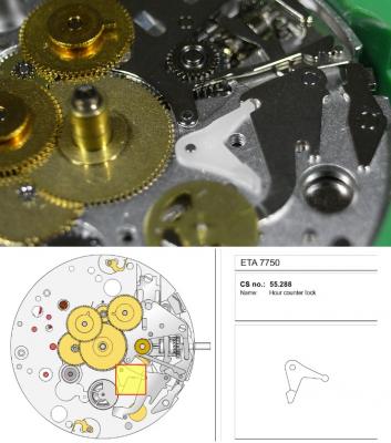
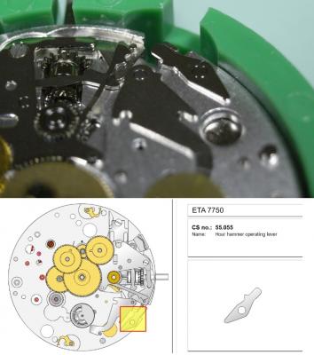
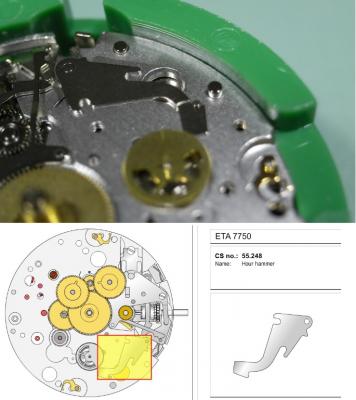
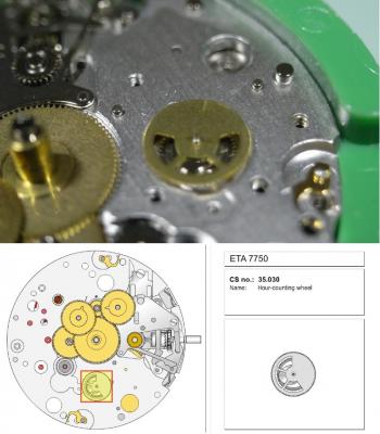
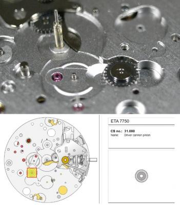
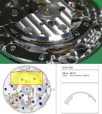
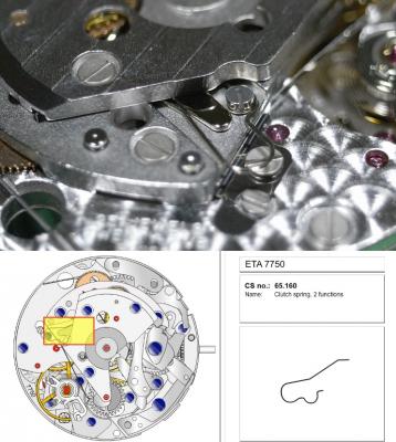
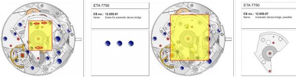
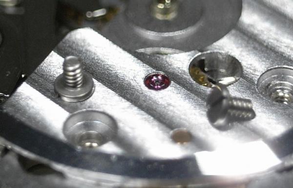
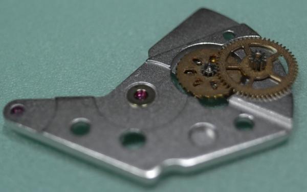
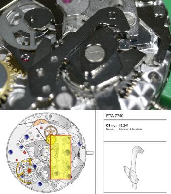
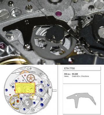
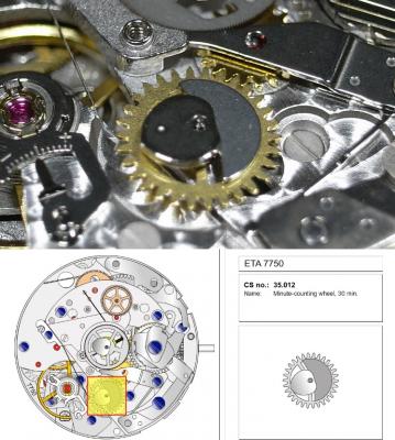
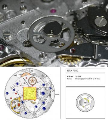
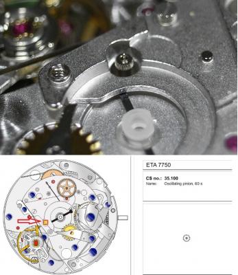
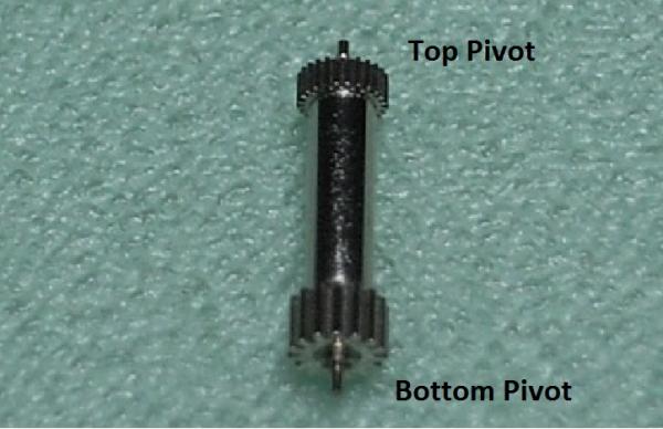
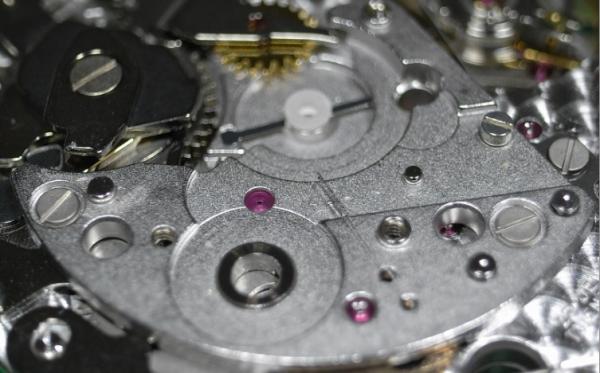
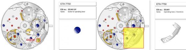
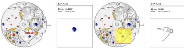
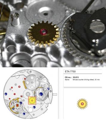
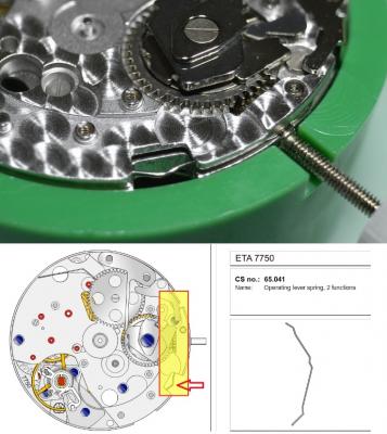
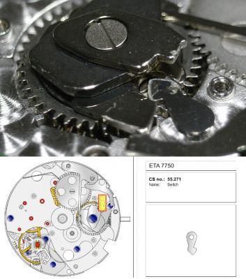
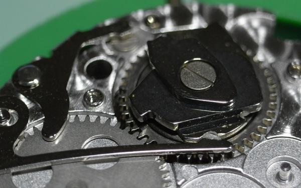
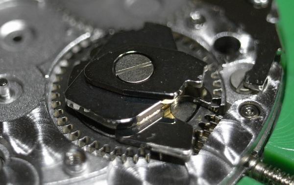
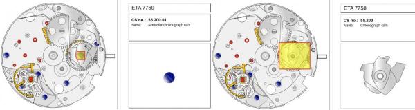
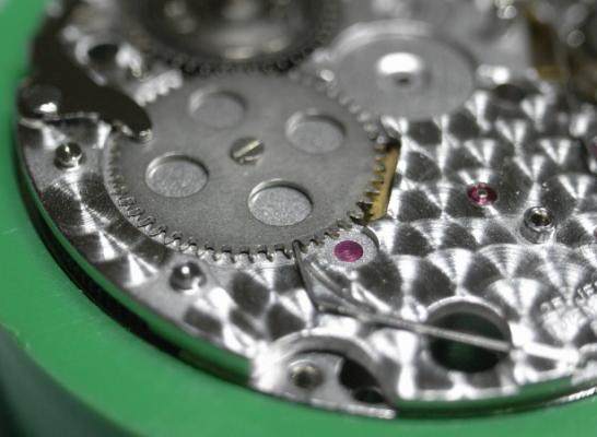
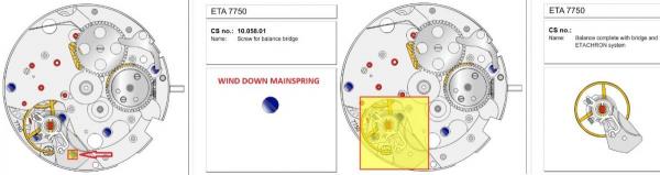
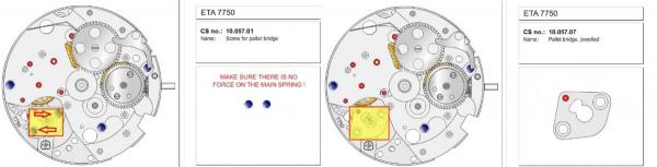
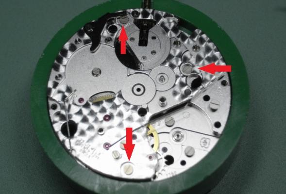
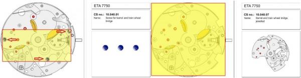
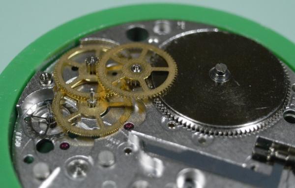
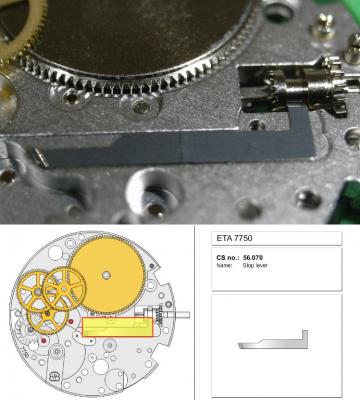
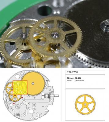
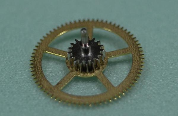
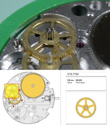
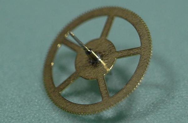
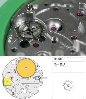
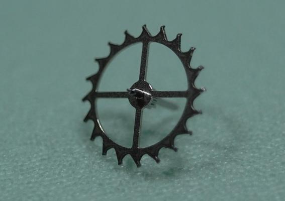
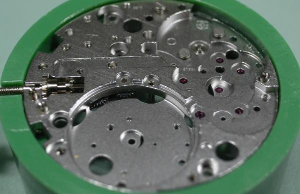
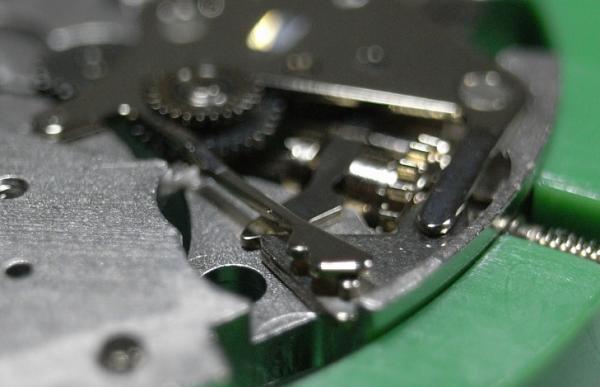
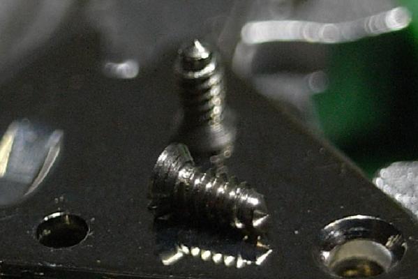
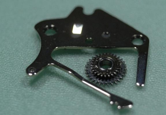
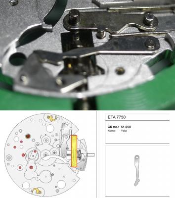
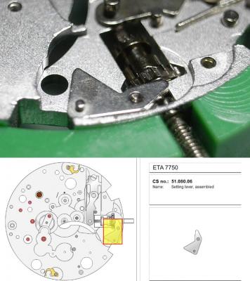
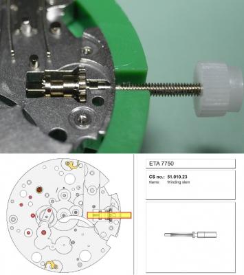
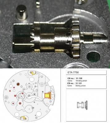
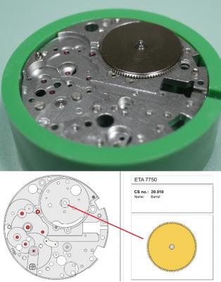
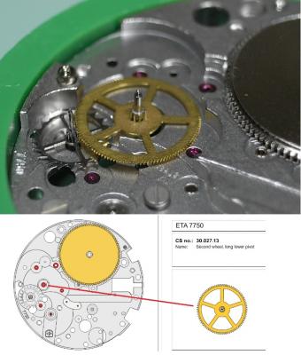
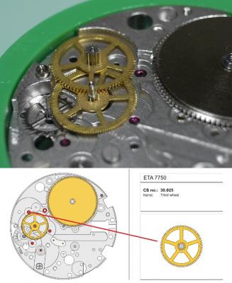
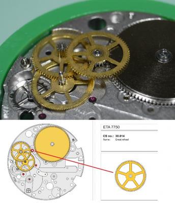
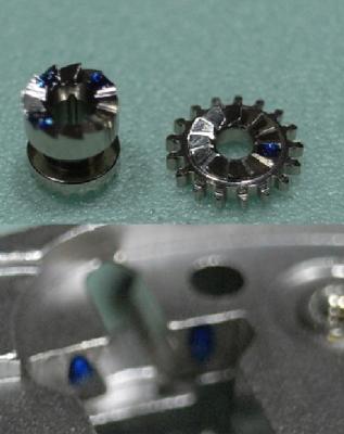
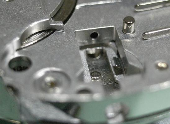
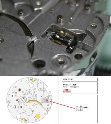
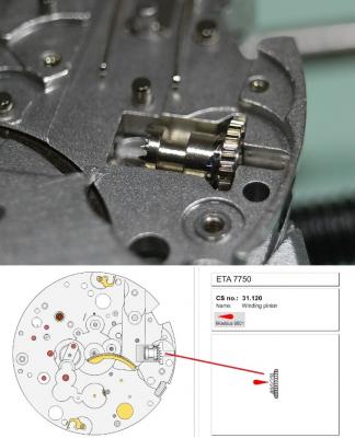
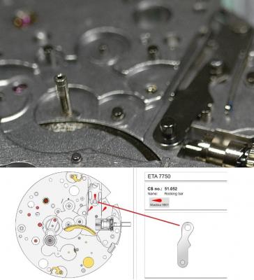
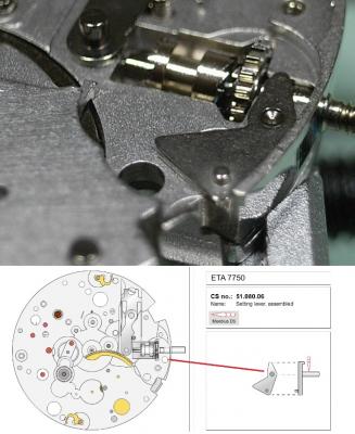
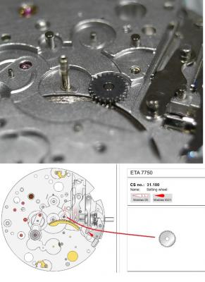
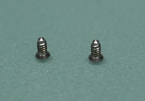
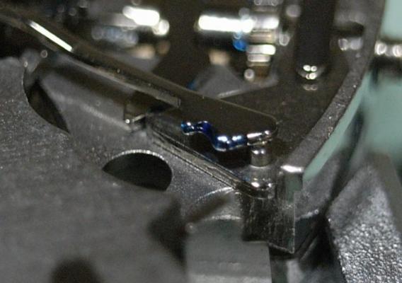
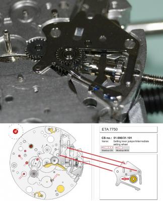
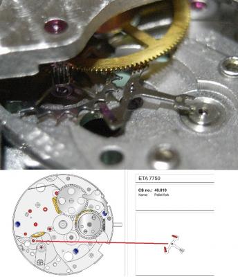
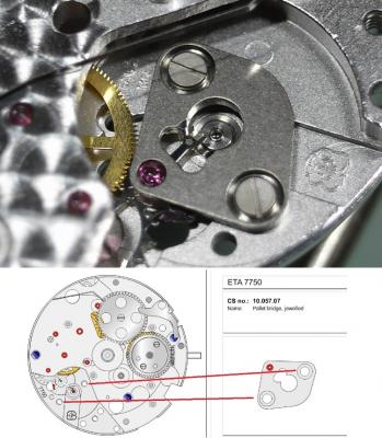
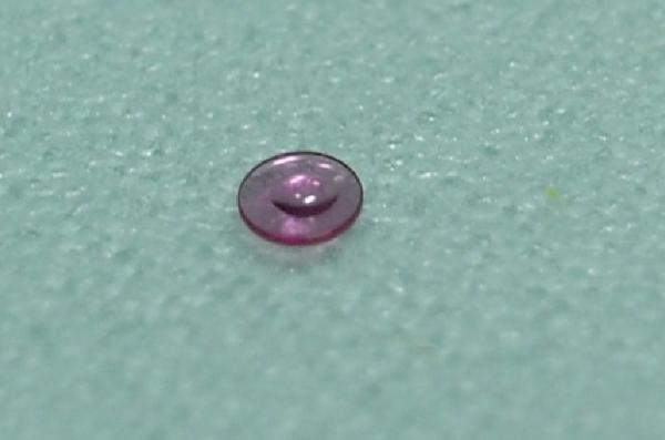
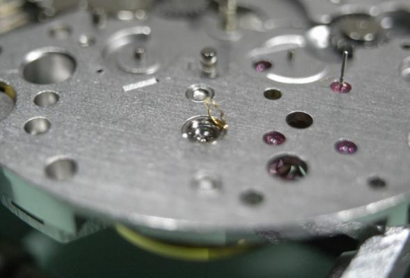
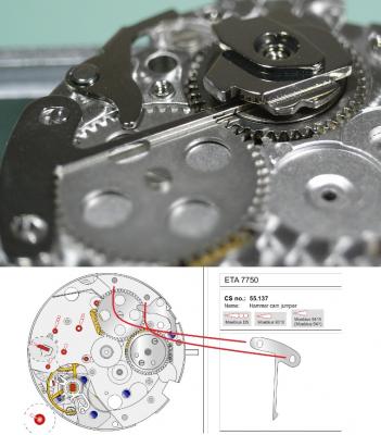
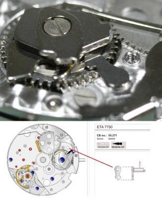
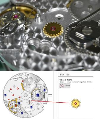
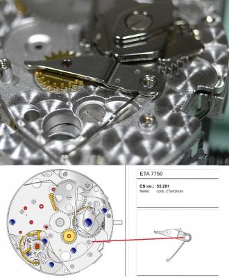
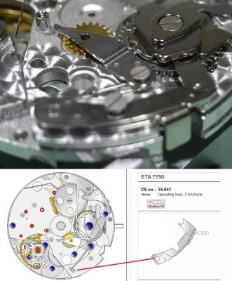
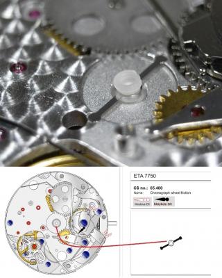
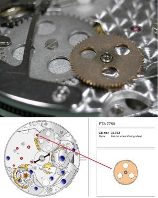
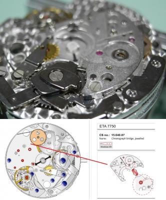
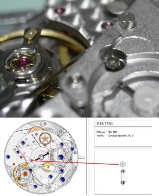
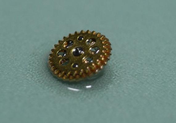
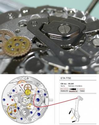
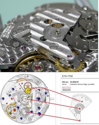
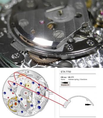
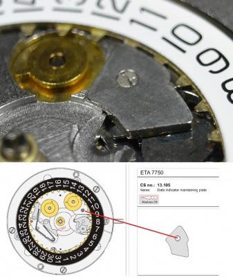
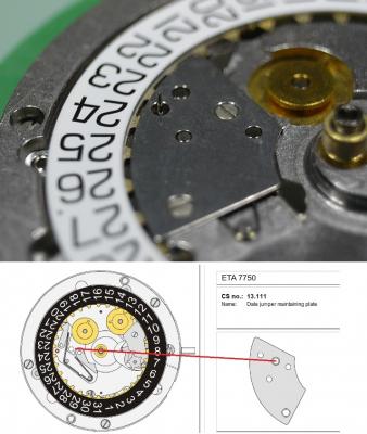
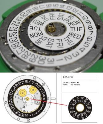
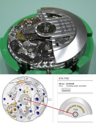
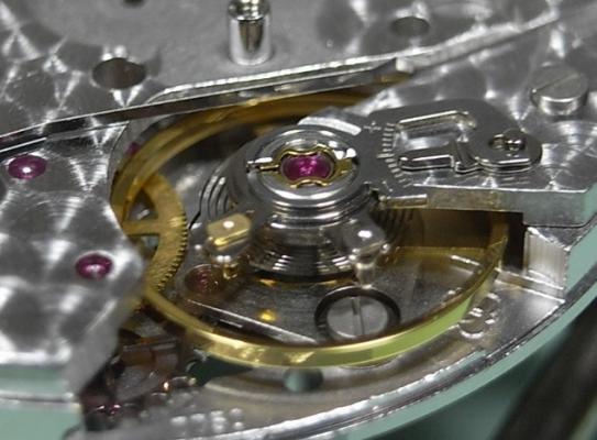
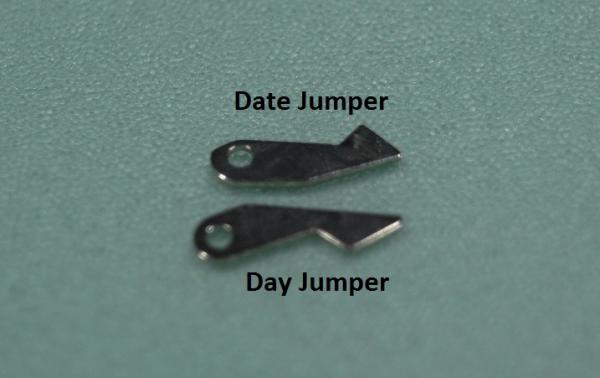
ETA 7750 Service Walkthrough The 7750 was first available in 1974, having been one of the first movements to be designed with the aid of a computer. It's hard to believe that the 7750 is still the industry standard movement for chronographs considering it's history. It was developed over 40 years ago by Valjoux, who was then a legendary movement maker that was part of the giant ASUAG conglomerate. But by the end of 1975 production was stopped due to the onslaught of the Quartz Era, and the 7750, along with many other mechanical calibers, was abandoned. Industry demand for this movement was so low that the stock produced in that 1 year manufacturing lasted until 1982! Such was the devastation of cheap Japanese produced quartz watches to Swiss manufactures. History may have forgotten the 7750 except for the local management at Zenith who ignored the orders by Valjoux to destroy the dies and equipment used to manufacture the 7750, instead hiding the equipment away from corporate eyes. You can find many more fascinating facts about this caliber online, and it's well worth the read. ................................................... This walkthrough will be very detailed, and I hope this will give people the courage to tackle this movement. I've serviced quite a few calibers, and this is one of the most beautiful, with a very logical layout. ETA7750 Tech.PDF If you have built your skills with basic movements, and become proficient in servicing them, I would highly recommend this movement to be your first chronograph to tackle. Lets begin. DEMAGNETIZE THE MOVEMENT BEFORE DISASSEMBLY. Remove the Day Indicator and store it in a safe place where it won't be damaged. Unscrew (0.8 Driver) the Jumper Maintaining Plate and remove it. Do the same for the Date Indicator Maintaining Plate Carefully remove the Jumpers Spring, holding it with a piece of pegwood so it doesn't ping away. Next remove the jumpers for the day and date. The jumpers differ from one another, so here is a reference photo so you can see the difference. Remove the Date Indicator and place it in a safe place where it won't be damaged. The last piece to remove on the Date Platform is the Double Corrector Now unscrew (1.4 Driver) the Date Platform and gentle pry it from the movement. Be careful when removing this plate, as there is a fine spring pressed into the plate that can be easily damaged. Here is a reference photo of the screws that hold the Date Platform. Remove the Hour Hammer Spring, once again using the pegwood to hold the spring while removing the tension. Here is a reference photo of the correct orientation of the spring. Remove the Hour Counter Lock. Remove the Hour Hammer Operating Lever. Next is the Hour Hammer, be careful when removing this item so as not to damage the Hour-Counting Wheel. Now remove the Hour-Counting Wheel. Remove the Date Indicator Driving Wheel Remove the Day Star Driving Wheel Then remove the Intermediate Calendar Driving Wheel Remove the Hour Wheel Then the Minute Wheel Remove the Cannon Pinion, which does not require a puller. The last component to be removed on this side of the Main Plate is the Driver Cannon Pinion. To lift the Driver Cannon Pinion I used what Mark used, a set of hand lifter from Horotec (MSA05.007); but you can also use a Presto Tool (30636-1) which will also work well. The dial side of the movement is now complete disassembled. Flip the movement over and unscrew (1.5 Driver) the Oscillating Weight. To remove the Hammer Spring lift it up gently over the automatic work and move it inwards. This will move the tail of the spring in a clockwise motion to the opening in the slots, which will free the spring. Slide out the Clutch Spring. Here is a reference photo of this spring, and it's orientation. Remove the screws (1.4 Driver) for the Automatic Device Bridge, and gently pry it loose. Here is a reference photo of these screws for the bridge. Once the Automatic Bridge has been removed, the two wheels for the automatic work are able to be removed. Below is a reference photo of how the sit inside the bridge. We now begin to disassemble the chronograph section of this movement. Begin with removing the Hammer, 2 Functions. Next remove the Clutch 60s, 2 Functions. Then remove the Minute-counting Wheel, 30min. Remove the Chronograph Wheel 60s, 30min. Gently lift out the Oscillating Pinion, 60s. Here is a reference photo of the orientation of this pinion. Unscrew (1.4 Driver) the Chronograph Bridge and gently pry it off the Train Wheel Bridge. Remove the Ratchet Driving Wheel. Remove the Chronograph Wheel Fiction. Unscrew (1.4 Driver) the Operating Lever, 2 Functions. Unscrew (1.4 Driver) the Lock, 2 Functions. Next remove the Minute-counter Driving Wheel, 30min. Slide out the Operating Lever Spring, 2 Functions. This spring can be fitting in both directions; but only 1 way is correct. Here is a reference photo of it's correct orientation. Remove the Switch. Here I digress from the order the SwissLab document illustrates the order of removal. They show to remove the Chronograph Cam before removing the Hammer Cam Jumper. This in my opinion is not the best way, as all the force from the jumper is pressing on the cam whilst your trying to remove it, and could lead to damage. Instead I move the Chronograph Cam until it reaches the notch as shown in the photo below. Then lift the Hammer Cam Jumper up to the top of the Chronograph Cam, which will release it's tension. Then, just as you removed the previous hammer, rotate the jumper to the opening in the slots, which will free the spring. Now you can unscrew (1.4 Driver) and remove the Chronograph Cam safely without tension on it. RELEASE THE MAINSPRING TENSION Once the tension has been released, unscrew (1.4 Driver) and remove the Balance Cock. Then unscrew (1.4 Driver) the Pallet Bridge and remove the bridge and Pallets. Unscrew (1.2 Driver) and remove the Ratchet Wheel. Then remove the Crown Wheel. Unscrew (1.4 Driver) the Train Wheel Bridge and gently pry it off the Main Plate. Note that one of the screws is under the Operating Lever. This needs to be moved out of the way to access this screw. The last level of this movement contains the train. Here is a reference photo of the wheel locations. Remove the Stop Lever. Remove the Great Wheel. Here is a reference photo of the underneath of this wheel. Remove the Third Wheel. Here is a reference photo of the underneath of this wheel. Remove the Second Wheel. Here is a reference photo of the underneath of this wheel. Note this has the long lower pivot. Remove the Escape Wheel. Here is a reference photo of the underneath of this wheel. Then remove the Barrel. This completes the removal of the train. Flip the movement over so we can complete the disassembly by removing the keyless work. Firstly, release the tension from the Setting Lever Jumper. Then unscrew (1.2 Driver) and remove the Setting Lever Jumper. These are unique screws with pointed ends, and below is a reference photo of them. This will also remove the Intermediate Setting Wheel. Next remove the Setting Wheel Then remove the Yoke. Remove the Setting Lever. Remove the Rocking Bar. Now pull out the Stem. Once the Stem is removed the Winding and Sliding Pinion should fall out of the movement onto your work mat. Disassembly of the 7750 is now complete If you've come this far, congratulation on completing the disassembly. Make sure you pegwood all the jewels and reinstall the Balance back onto the movement for cleaning. Assembly of the movement will be posted as soon as I complete the write-up.


 1 point
 -
Way to go Johnnie,....feels good when you can recognize and solve a problem .1 point
-
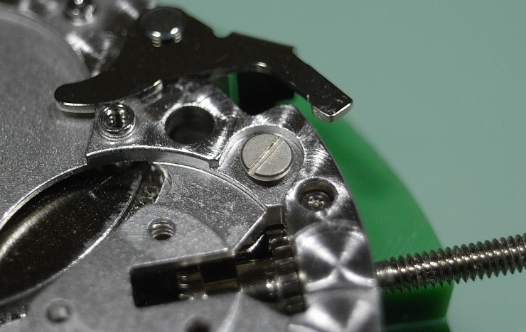
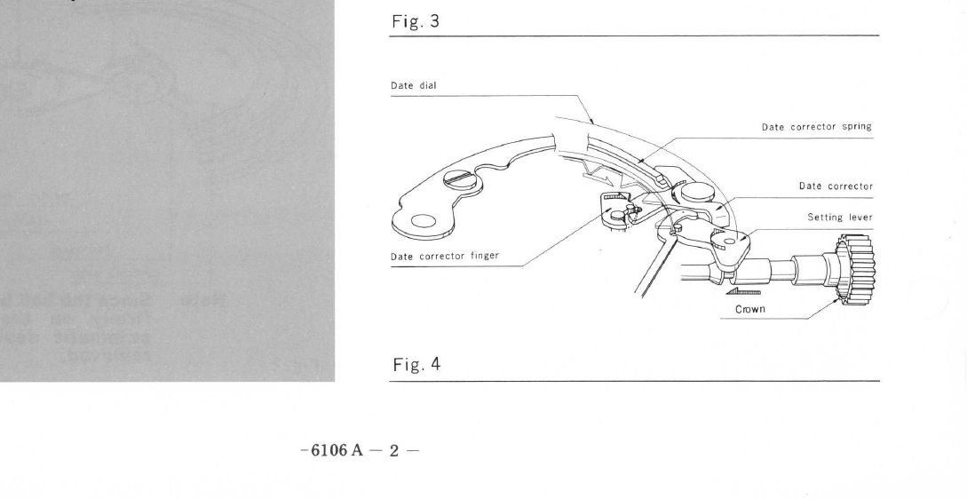
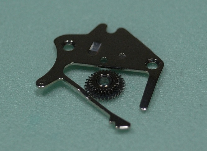
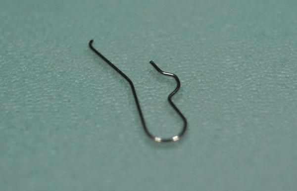
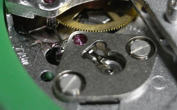
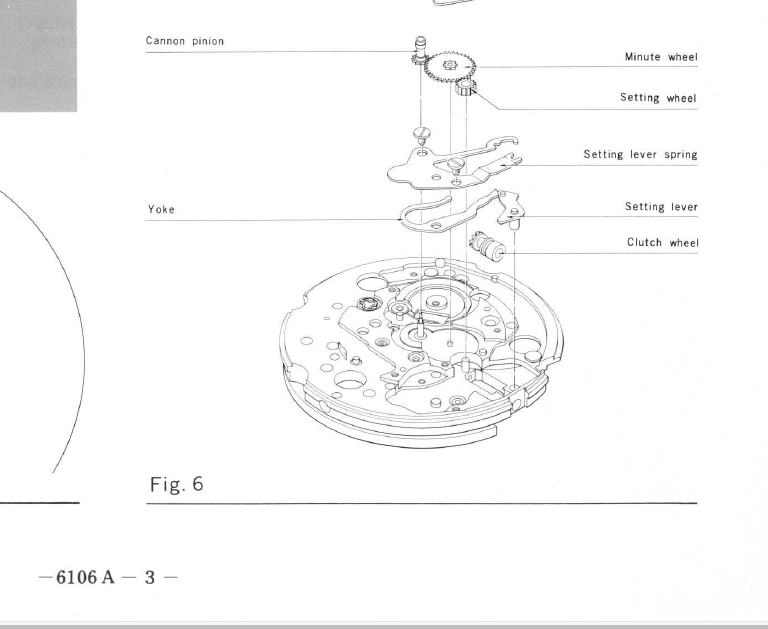
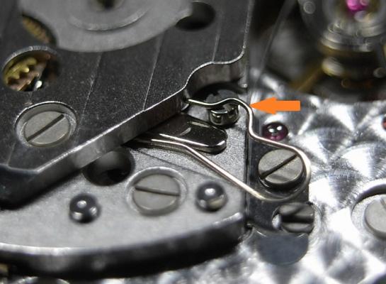
Is the finger of the setting lever spring broken off ? It keeps the pressure on the setting lever that holds if firmly in place and provides the clicks for positive setting positions...[ 1st position , 2nd position for setting . It is a common problem tor these delicate fingers to get broken off when refitting . They are necessary for proper setting operation.

 1 point
 -
Likewise with my new workshop layout, I raised my ain working area, and its so much better now.1 point
-
Well, any repair work can ruin the object, if not done properly. I never wrote that buffing does not remove metal, the idea is to remove less, and to move back some in place. Good video with demonstration1 point
-
Johnnie; Le Carl wrote a book on "watch repairing' - old, basic but very good. ( one of many good picture books). vin1 point
-
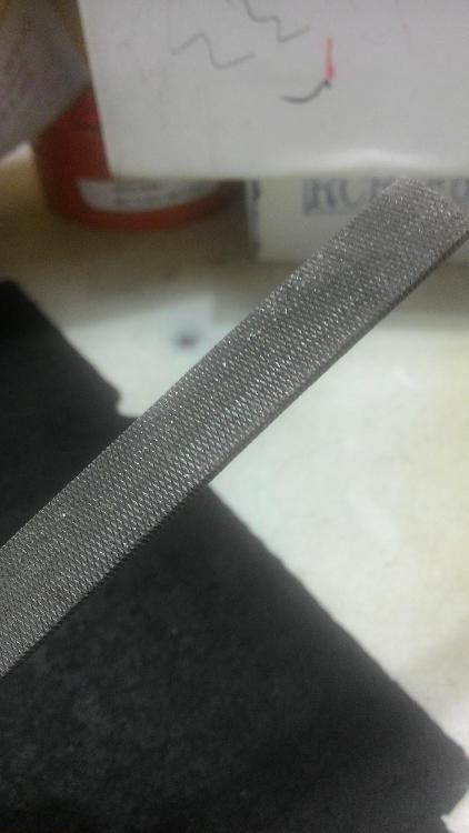
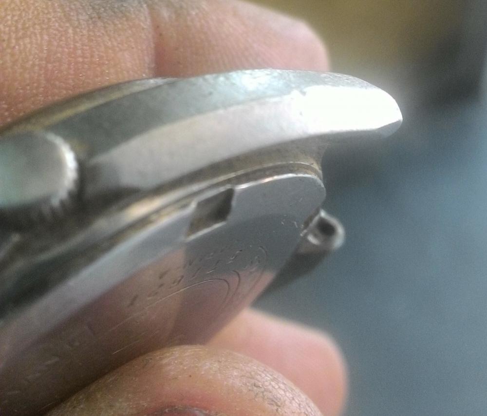
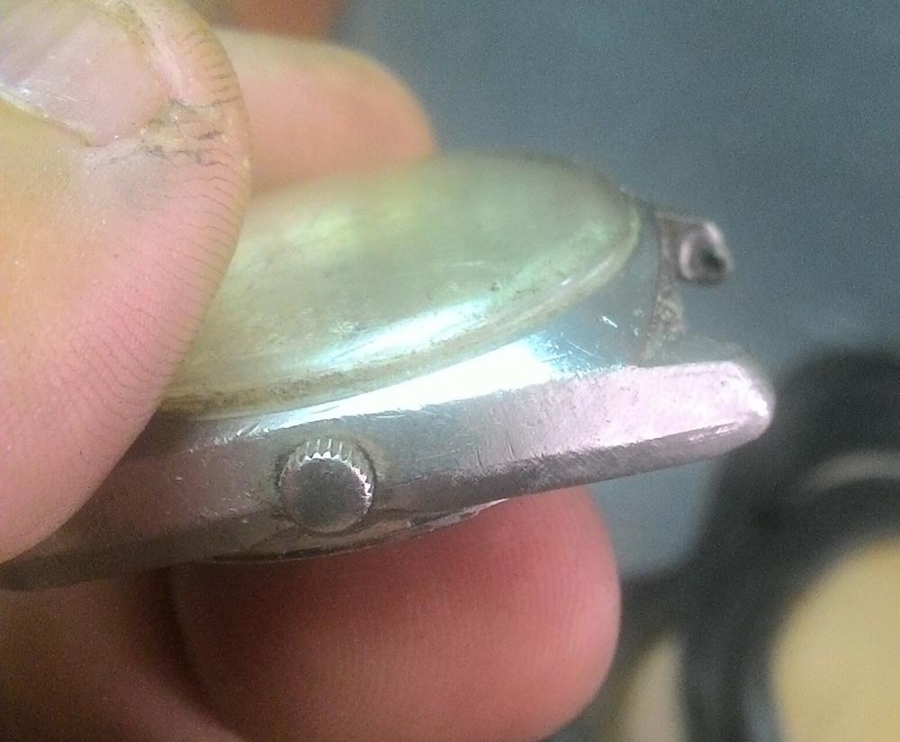
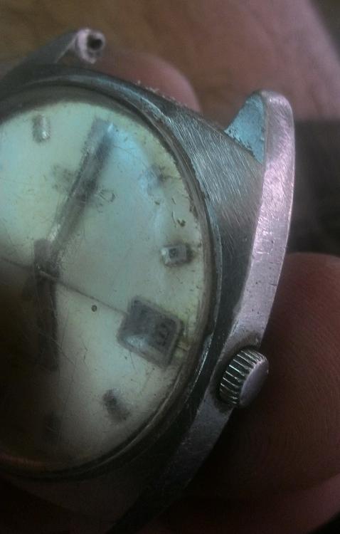
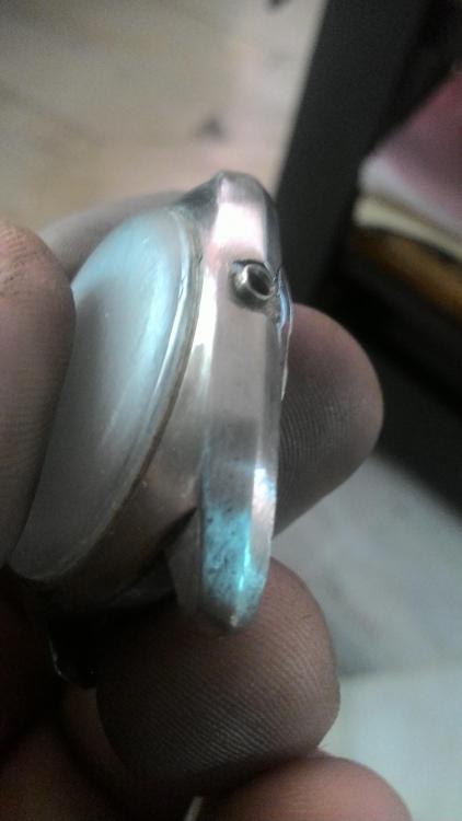
I'm not usually a fan of polished cases as I find that polishing removes the sharp edges and a lot of the details are lost. In this case, however, I can't believe it matters as the case is really rough. Since a lot of the gouged are pretty deep, I start with the roughest grade of sandpaper. I'm not joking, using sandpaper will take ages so I'm using a metal file. The file was followed by sand paper so that instead of big gouges you have smaller voices. The crystal got a good going over with the sandpaper. Here you can see where the area surrounding the gouge has been ground off. It is important that you handle the file in such a way that the area is rounded off. You want to avoid flat-spots as this will be visible when polished in the form of irregular reflections. The left side was massaged to remove the nick at the nine o'clock position. The file was wielded on the case back as well.. To be continued....


 1 point
 -
I have now a a 1900 and the difference is worth it. Much better color display to know the direction to move the arm to correct beat error, few more settings, auto power off. There is another thread with more in depth discussion. For a good saving buy on aliexpress not eBay.1 point
-
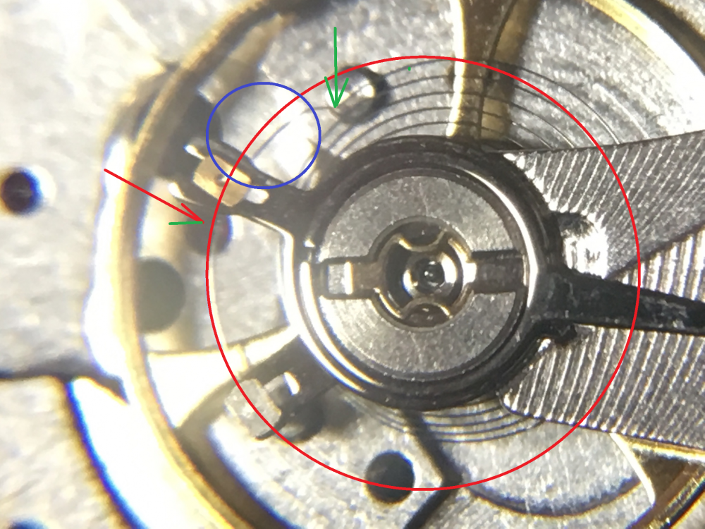
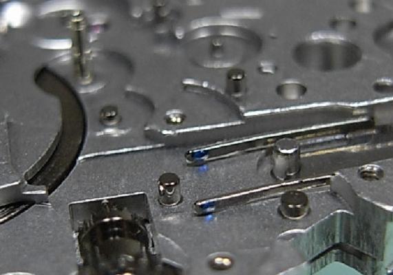
See the red circle! The end curve should follow it =see the difference marked with blue circle). So the regulator pins are not in the correct place or the end curve is also bent. The middle of the regulator pins should have the same distance to the balance than the stud mount point. From this picture it seems that a bending is also at the green arrow,
 1 point
 -
I ordered one of these from china and am still waiting. Here is what I have Sent from my iPhone using Tapatalk Pro1 point
-
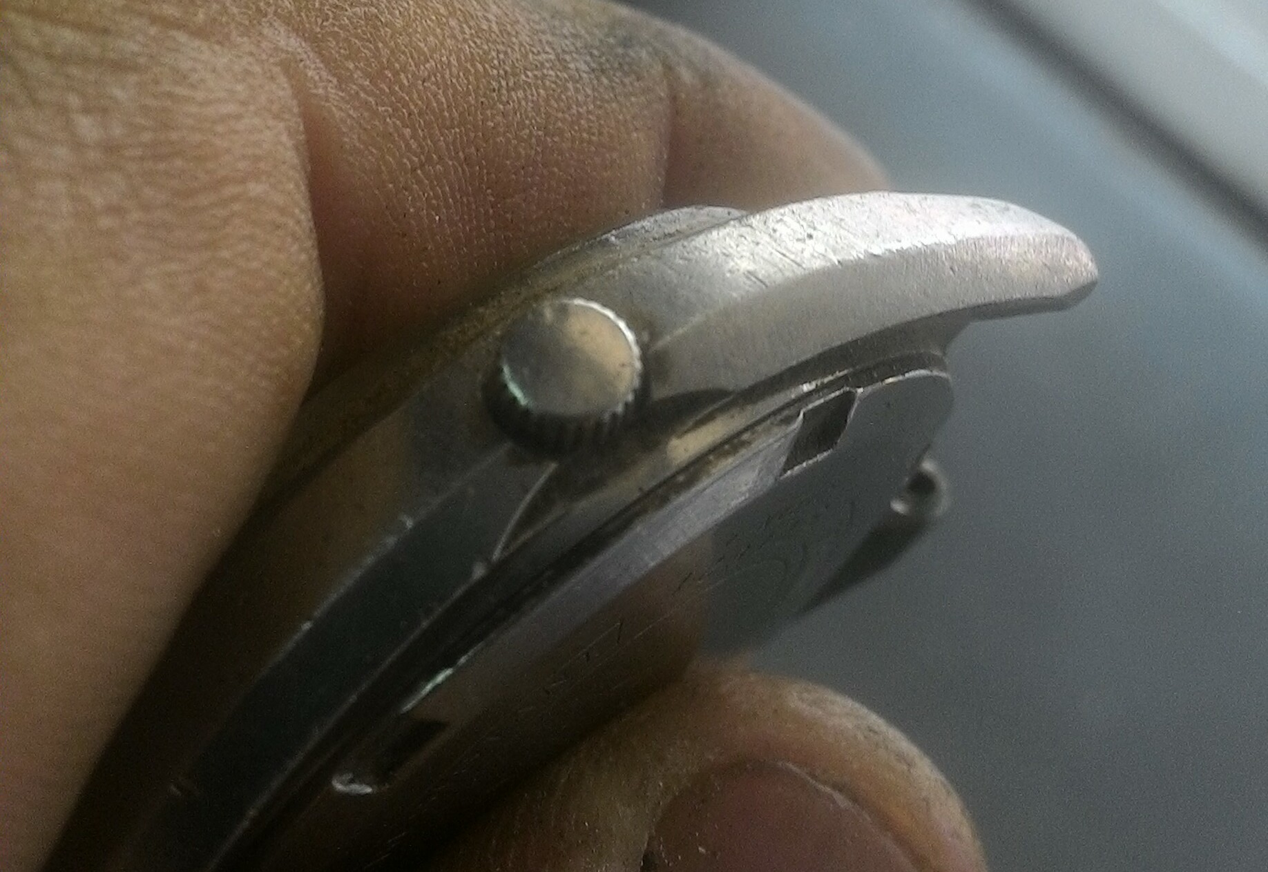
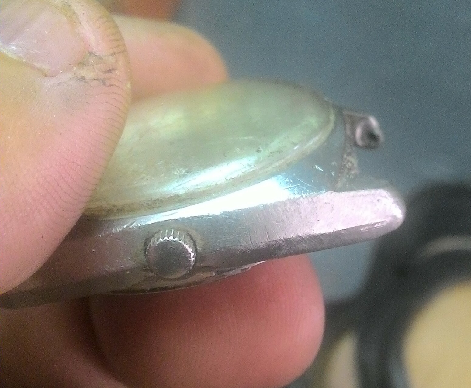
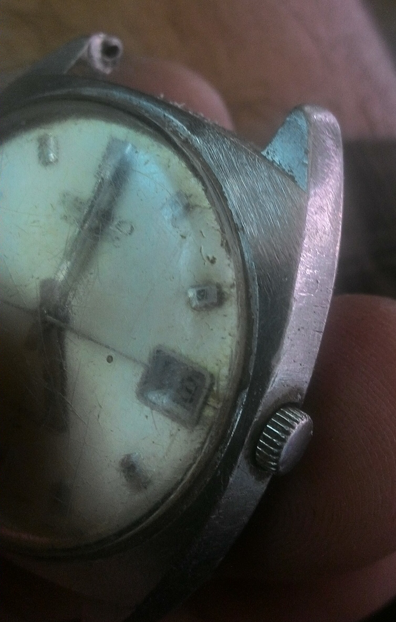
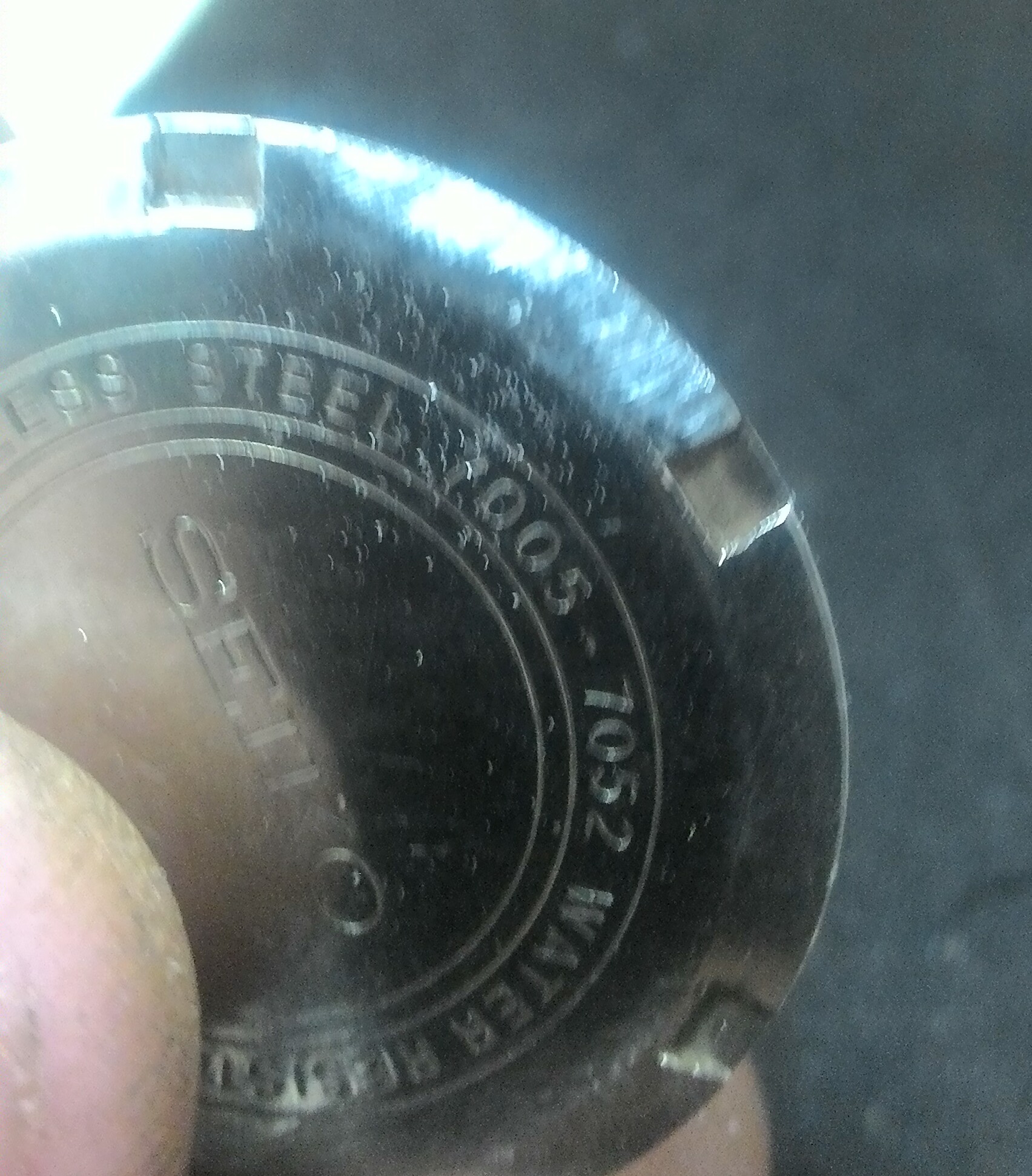
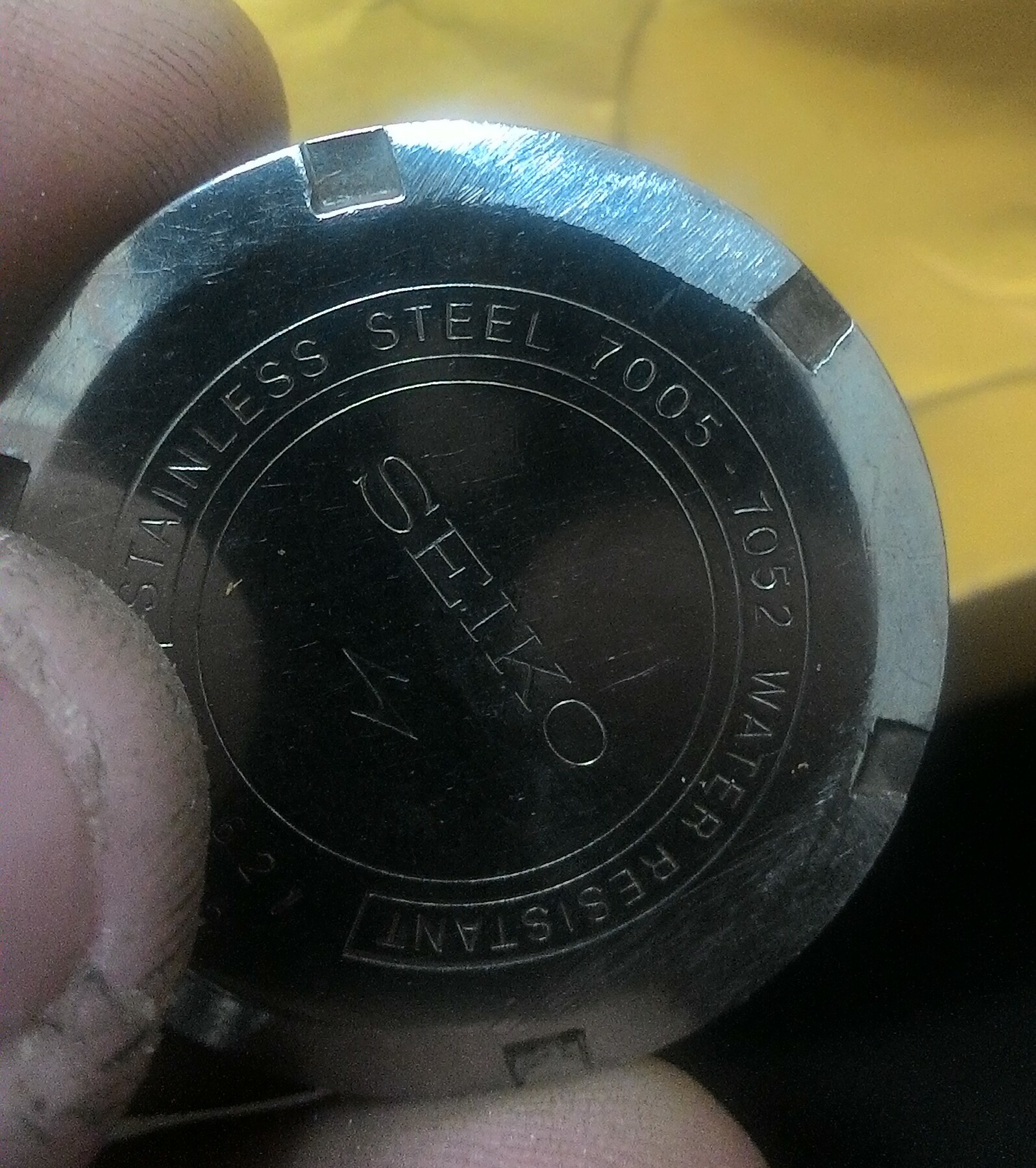
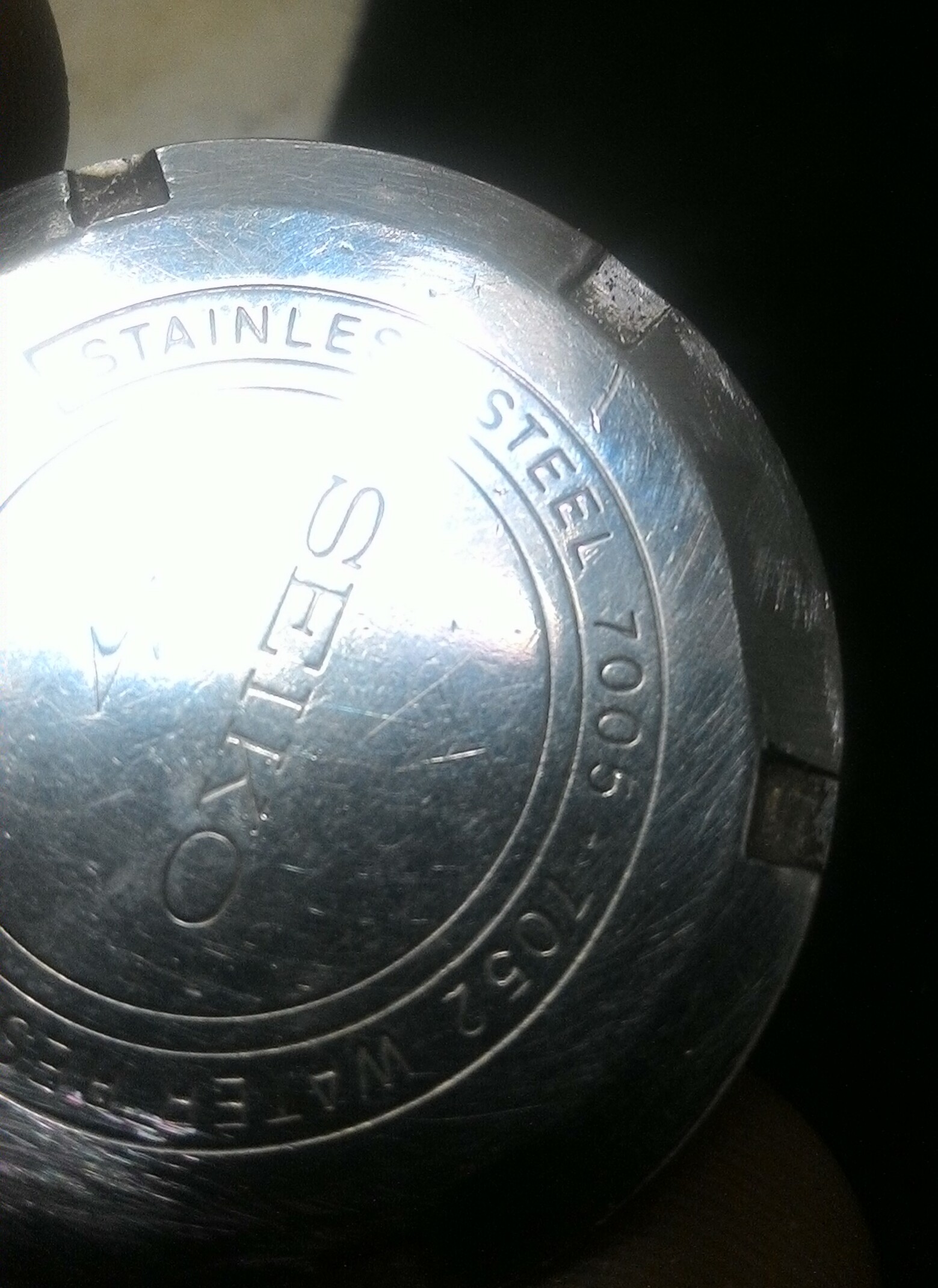
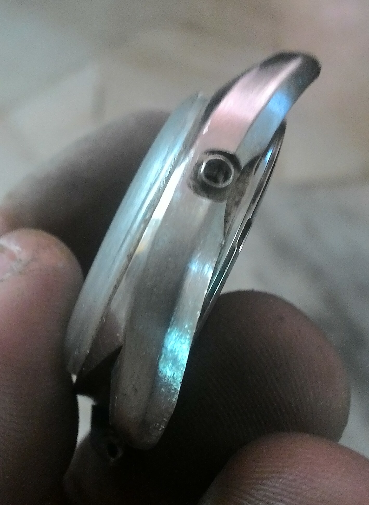
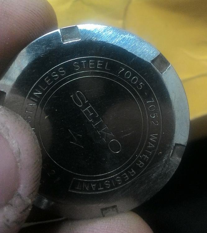
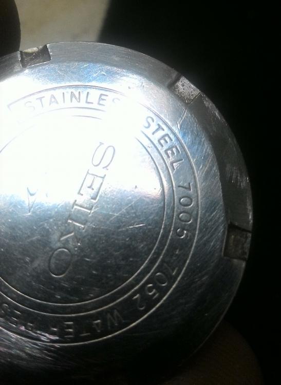
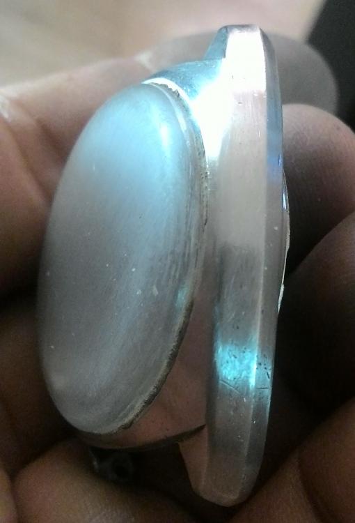
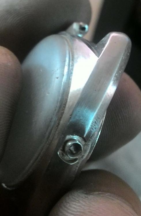
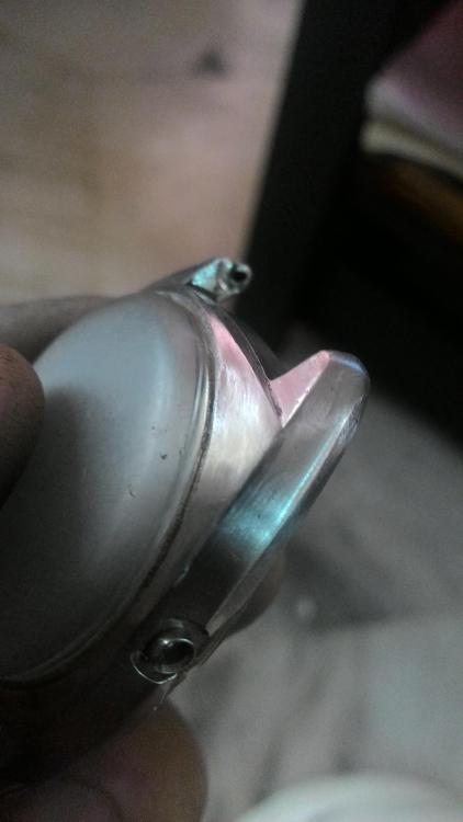
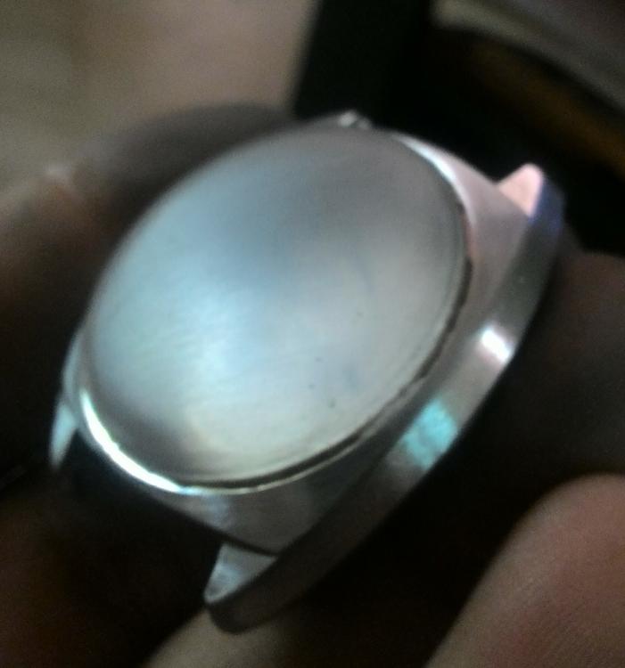
Oh yeah! Finally it opened. Thanks Ray. Thanks Frenchie. It worked after 2 tries. First try, I heated the watch in the oven, then transferred to the vise block , mount the case opener carefully, apply pressure with the aid of a mill press, then apply some torque to open, then hit it with the coolant. Didn't work. The problem, getting it setup took time. Maybe I cooked it too much to. The second time, it set it up ready to open position ( vice block, case opener aligned pressing on the case. Then I heated the whole setup with a heat gun, then hit the back with the coolant and it finally gave. I still had to open it half way using the setup since after cracking the case I still could not open it by hand. Again, thanks for the response . Pics enclosed. Sent from my iPhone using Tapatalk1 point
-
To be a bit more specific, as a reference point, if that case is made of 316 Stainless and if it's 1.75" (44.45mm) diameter then, heating the case to 115F (46C) and cooling the back to 45F (7.2C) will give a 0.002" (0.051mm) clearance in the threads. This is a rough approximation but should be close enough for this application. Please see this chart for other coefficients. http://www.engineeringtoolbox.com/linear-expansion-coefficients-d_95.html There is a simple calculator somewhere on that page too. Also, I understand how this may seem inappropriate for watches but, I would also put a couple drops of light oil on the seam where the threads meet. Doing that in-combination with repeated attempts to cause thermal opposition (aka sweating) in the fitting of the threads is a trick used in Tool, Die and Fixture making on a daily basis... How you go about heating the case to 115F ???? Beats me! That's up to you. Ray1 point
-
If you use method one you don't need to leave the hairspring dangling. I use a balance stand and a bit of rodico and it could sit on its standard for years if necessary. Have attached some pictures for demo. Just remember when taking the balance assembly of the stand to hold the wheel gently incase lower pivot sticks in the rodico. Then release from the rodico. I think people prefer method 2 to avoid having to flip the wheel over when working on the balance. Sent from my SM-G920F using Tapatalk1 point
-
For me I'm staying as a hobbyist, I would love to get a BHI accreditation for watch servicing (up to say day date complications) I would proceed at a late date to more complicated movements. But for me it's the cost of the even the basic courses, it just starts becoming too costly, which is a shame for the industry as I know there must be lots of people in the same boat as me, all very passionate and basically self taught and pretty damn competent, but cost is phrohibiting us actually proceeding into the industry and keeping it alive. My local smith who has two other smiths working with him has a 6 month waiting list for work to cross his benches!!!!!! The works out there but I'm afraid I'll have to stick to my hobby room and tinkering only. Sad but the industry is shooting itself in its foot by out pricing some very talented people. Just my two penneth worth.1 point
-
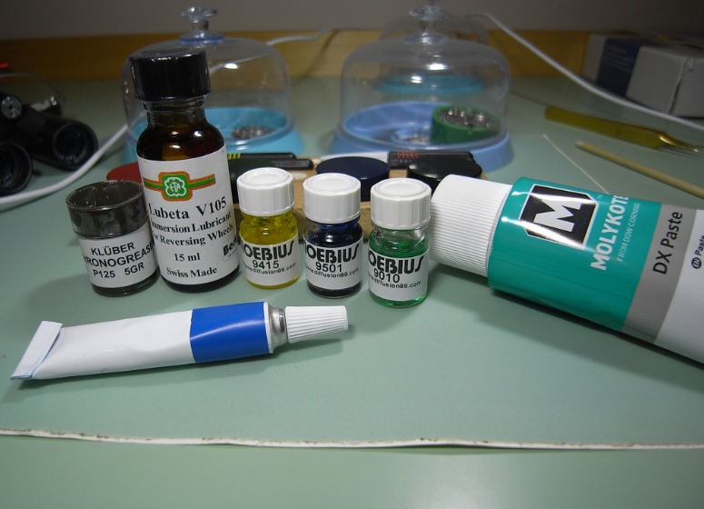
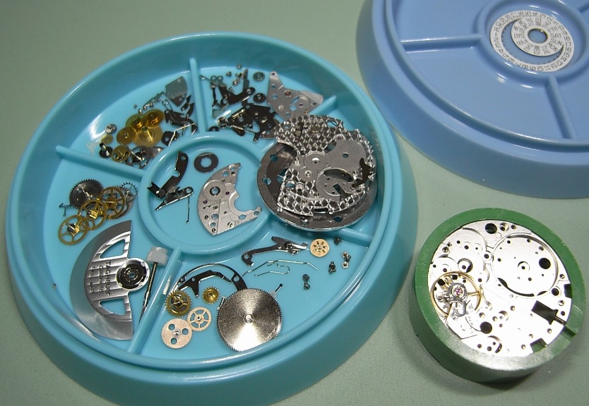
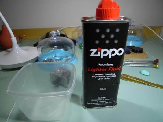
Here we go with part 2. Now it's easy to note, that I'm not a professional as the cleaning equipment is only... ehm... semi-professional. Special treatment for the balance and the pallet fork. The equipment for oiling and grease. Inserting the new mainspring. Reassembling the train bridge. Surprise: Much easier than on other watches, the parts fall into correct positions by themselves. Nice. Barrel bridge and ratchet system. The keyless works. Assembling and oiling the Pallet fork. The return of the balance. A drop of oil for the balance and escape wheel stones. Winding up and...it runs! Oops, some adjustment needed. Better. Reassembling the automatic device. Inserting the screws for movement and dial. Time for the cannon pinion and the hour wheel. Bringing back dial and hands (oh, I love those Maxi dials). Back in the case... ...and completed with the automatic device. Some grease for the gasket. Got it. It's called a wrist watch, so it's for the wrist not for the safe.1 point
-
Hi jdm, As CB said, in Seikos, amplitude is not too great. So, your primary goal is to make them work continuously in all positions. Remember, if running fast, most likely it is a shorted hairspring. In your case, I suspect the pivots. They could be rusted, bent or broken. This may be an issue detected when the watch runs in one position but doesn't in another, usually an oposite. Also, check for fork jewels misaligned, worn, and/or broken...or similar problem in the balance/impulse jewel. Those are critical areas for the watch to work properly given that the rest is OK. Hopefully, it is just a little overlooked detail. It sometimes happens that we are so focused on the Gremlins that a little thing may just pass us by. Happens all the time. Remember magnetism is one of those we overlook...and some demagnetizers (read cheap) might add the magnetism. Cheers, Bob1 point
-
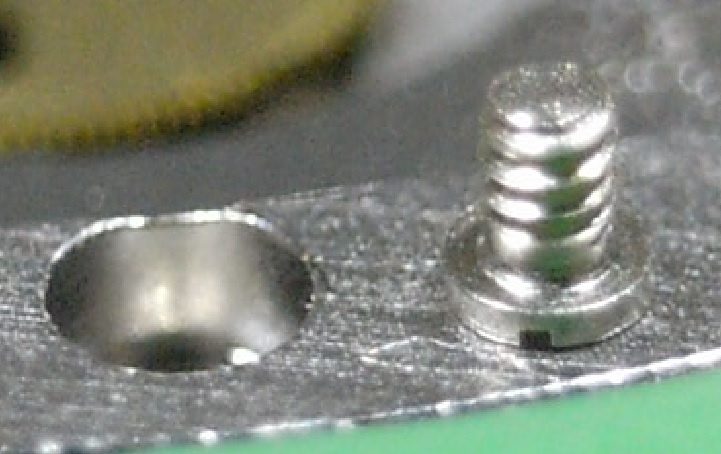
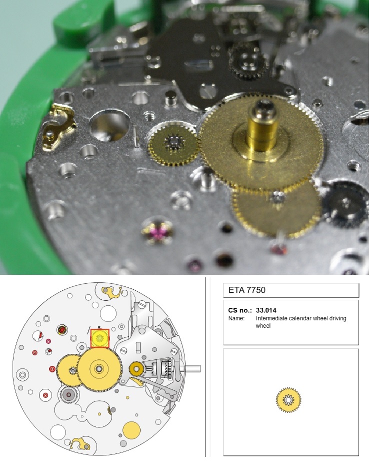
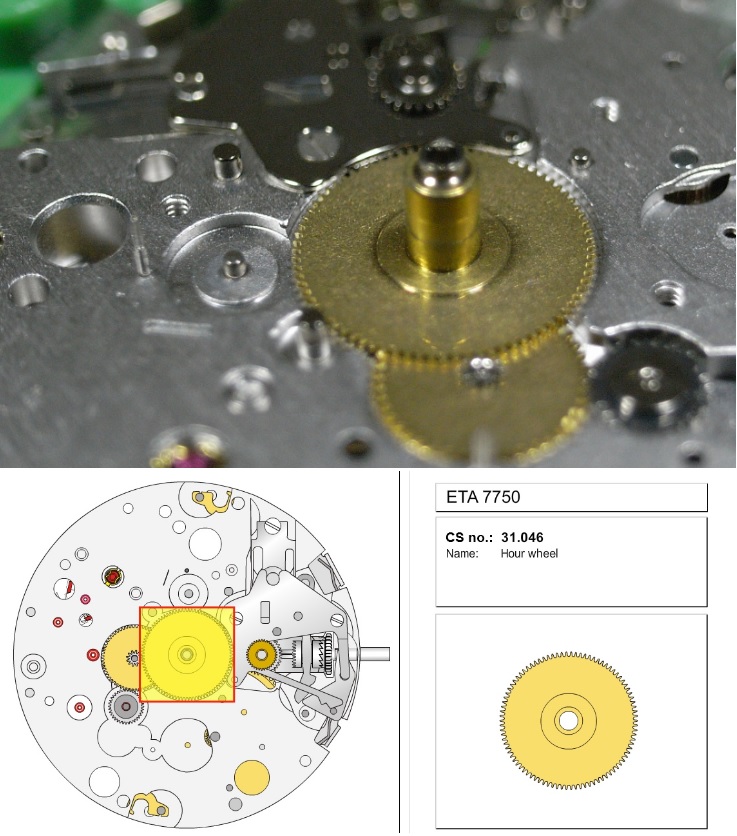
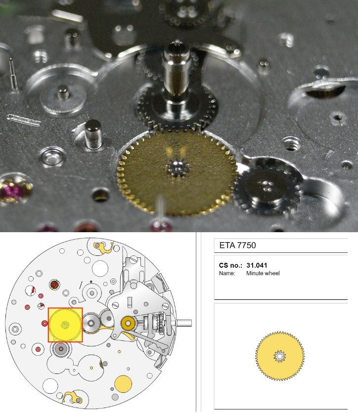
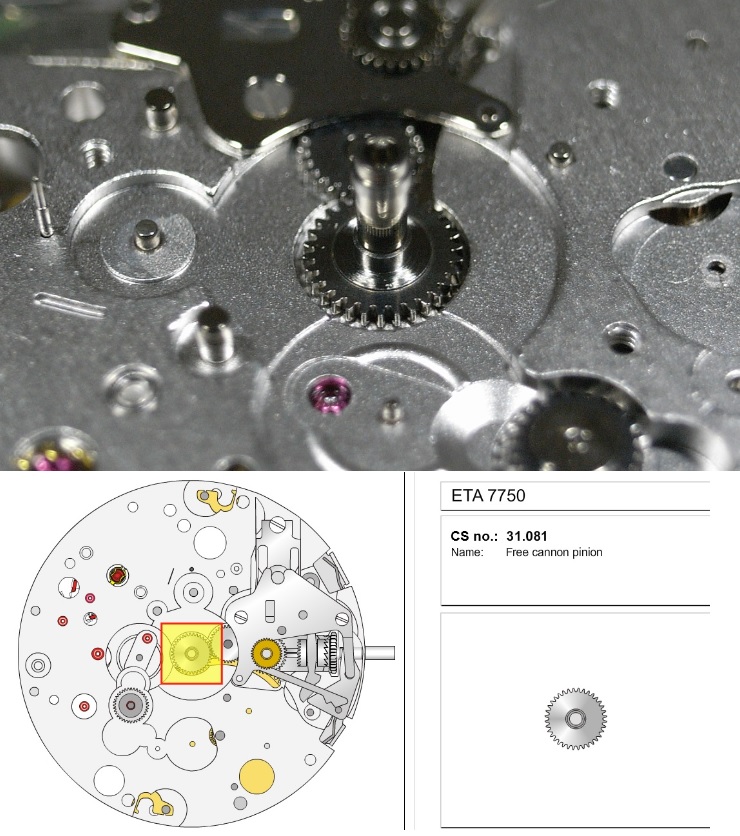
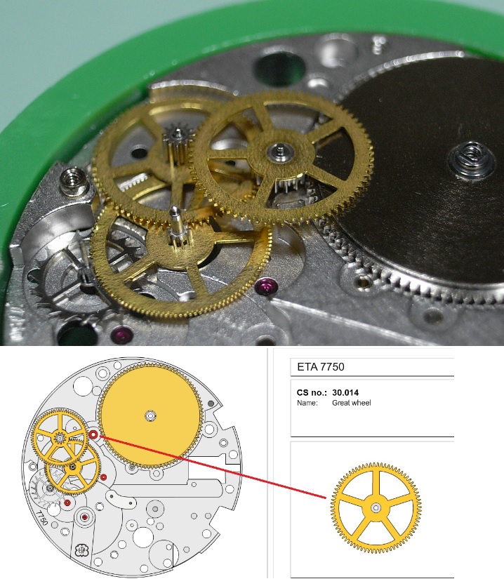
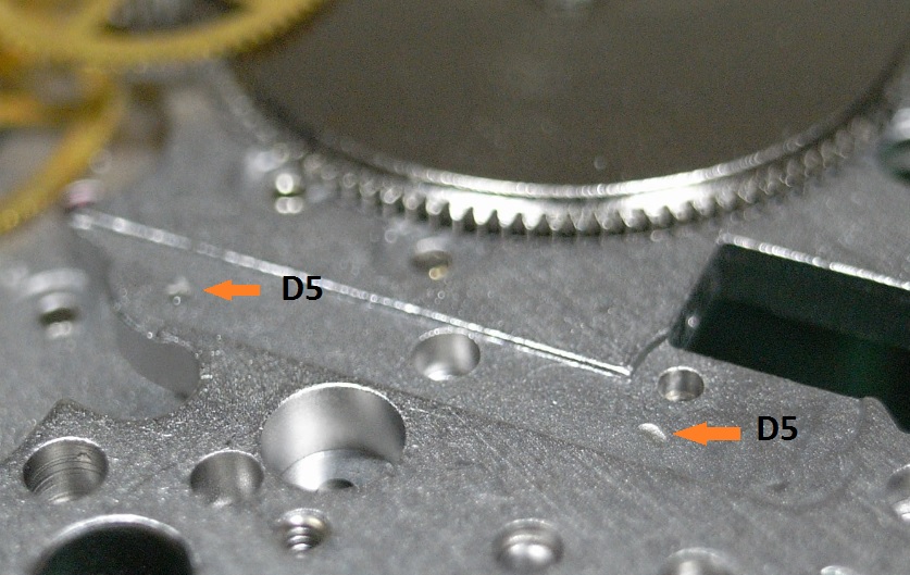
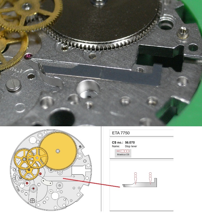
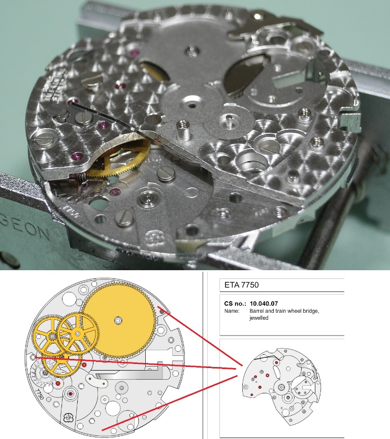
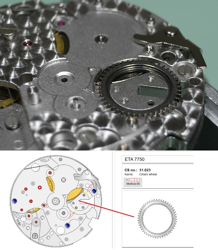
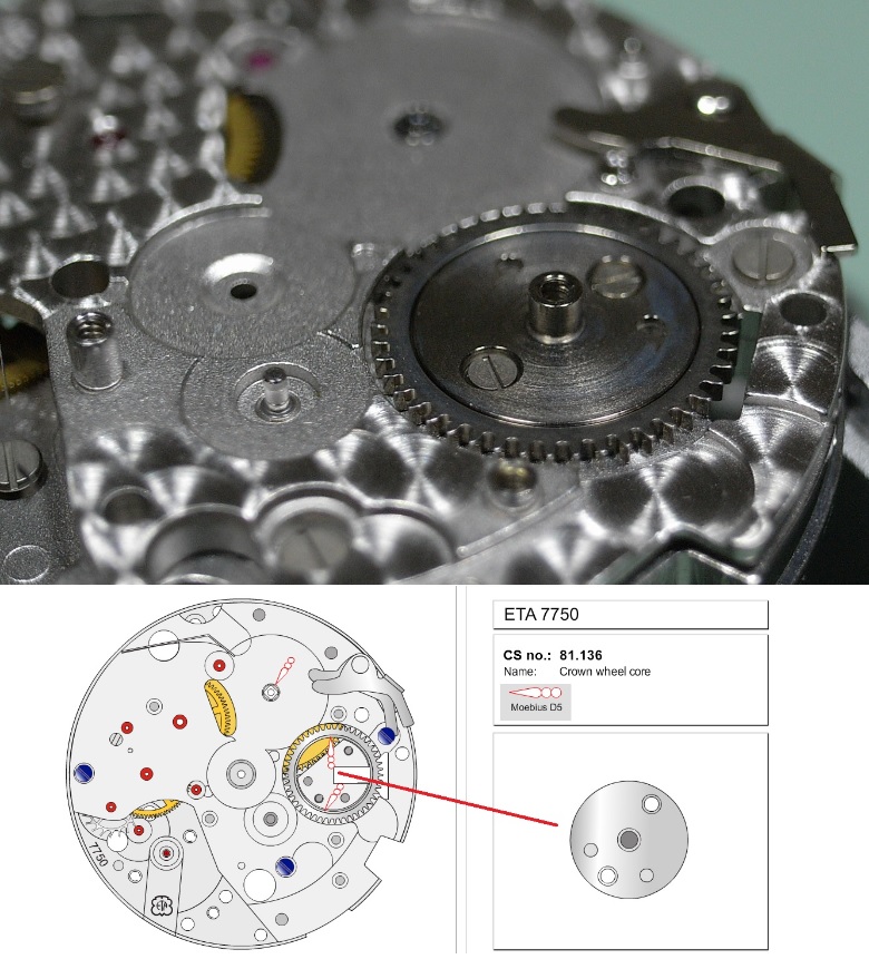
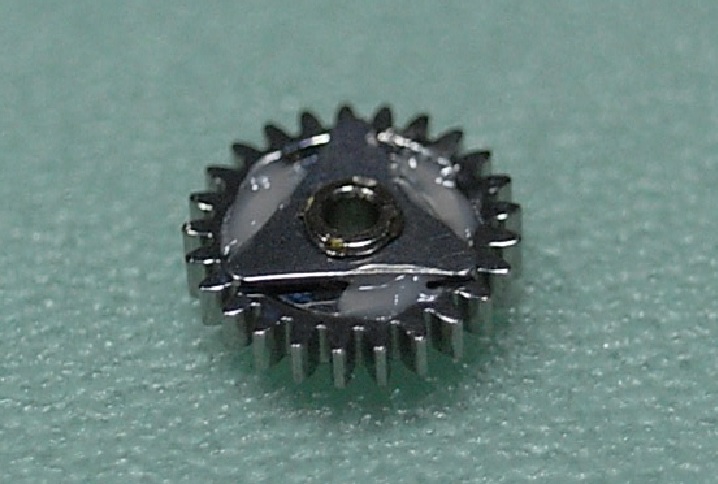
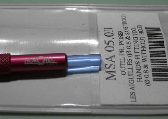
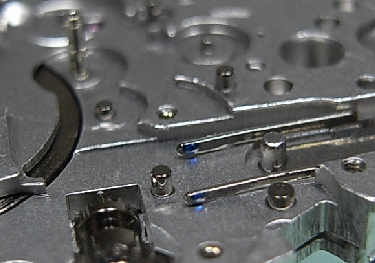
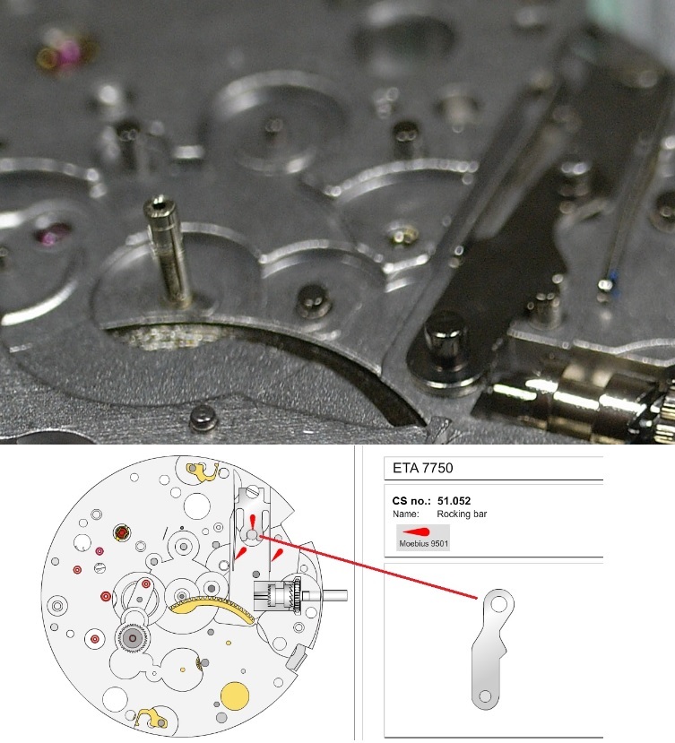
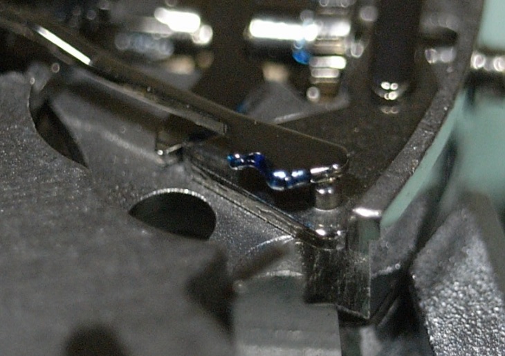
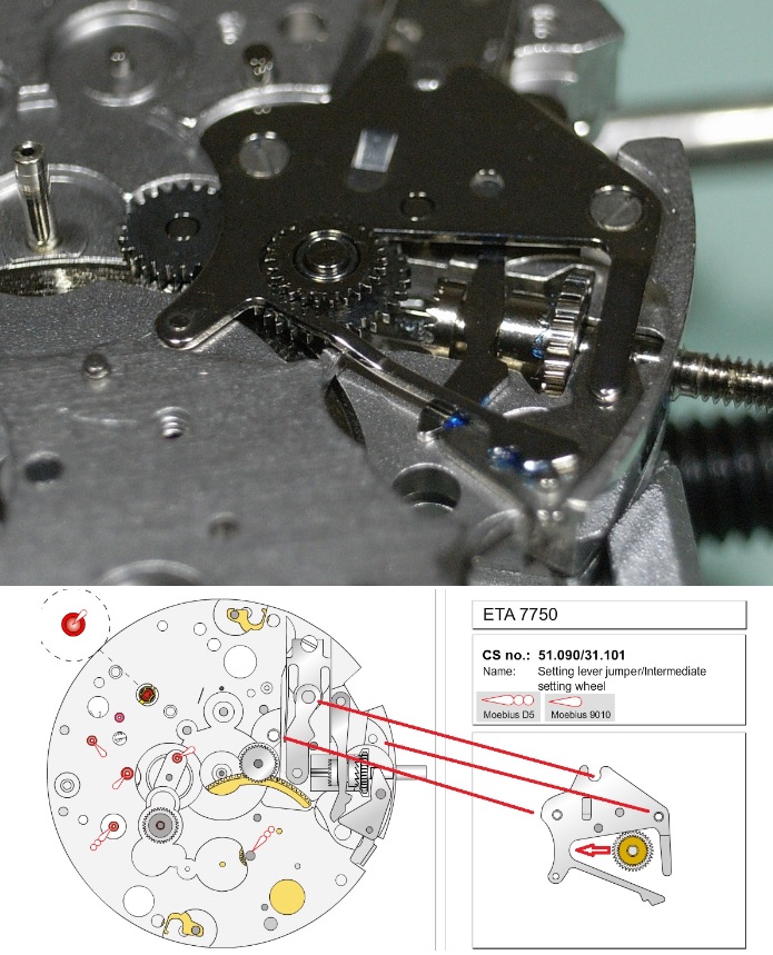
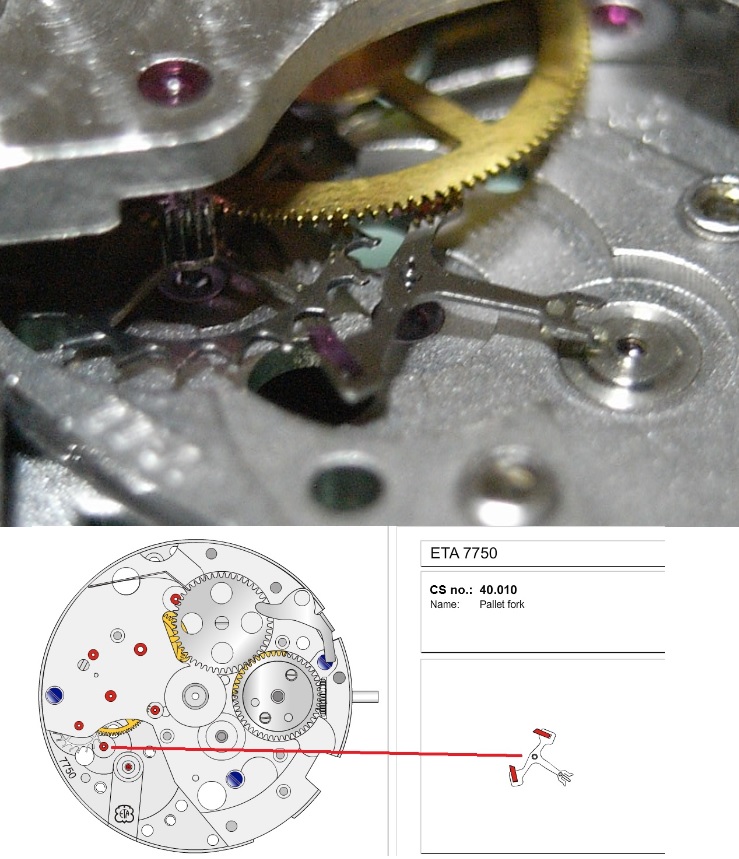
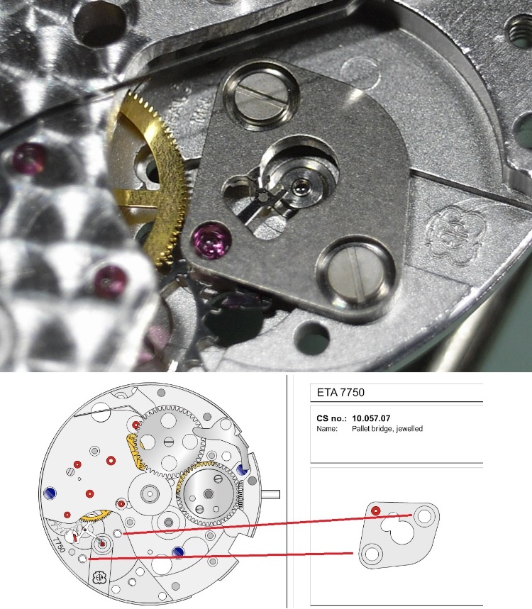
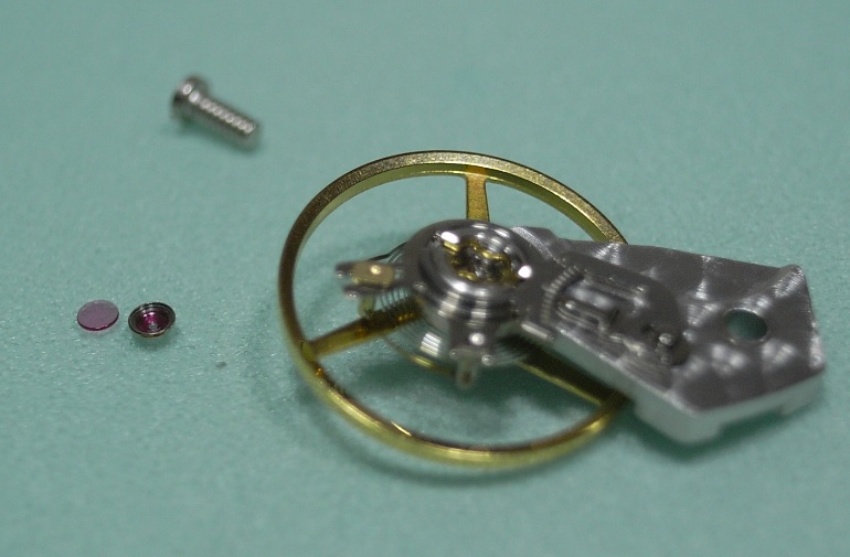
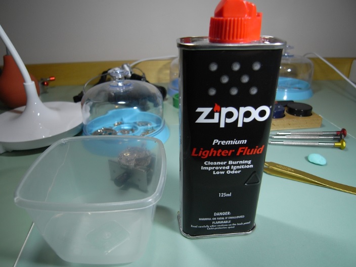
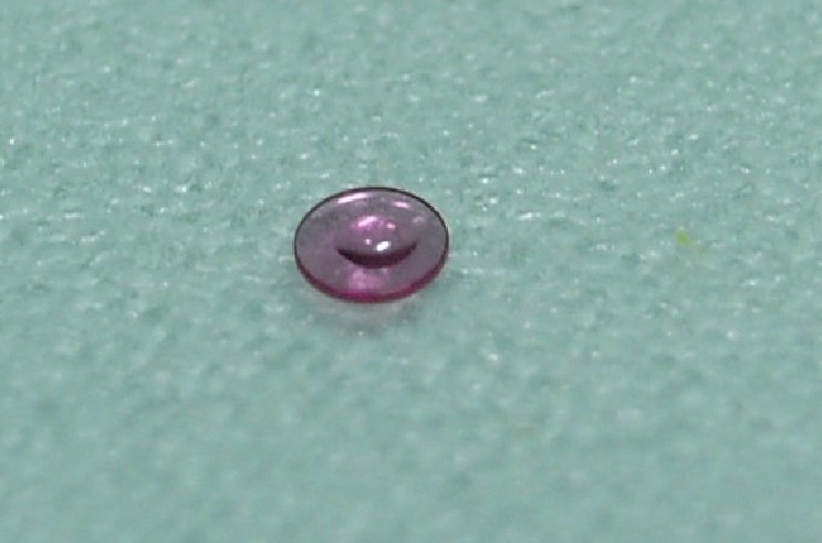
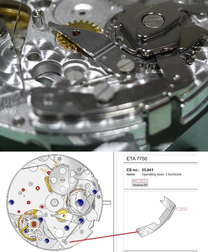
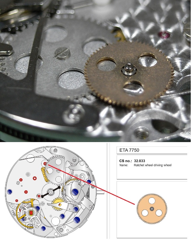
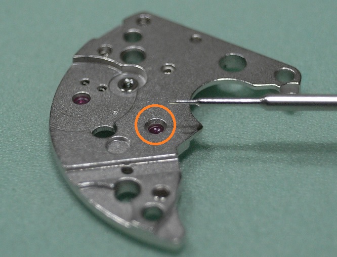
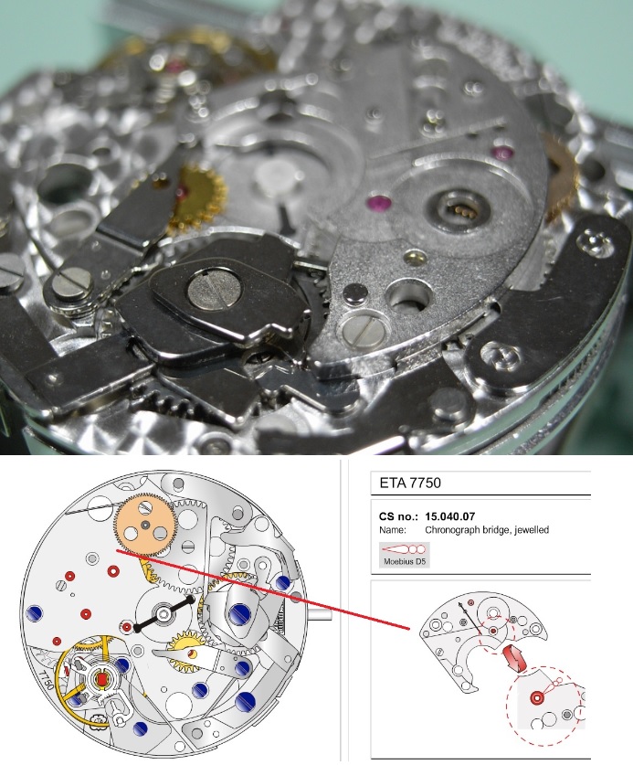
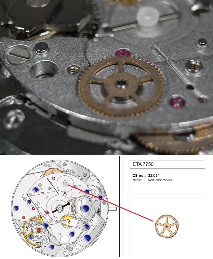
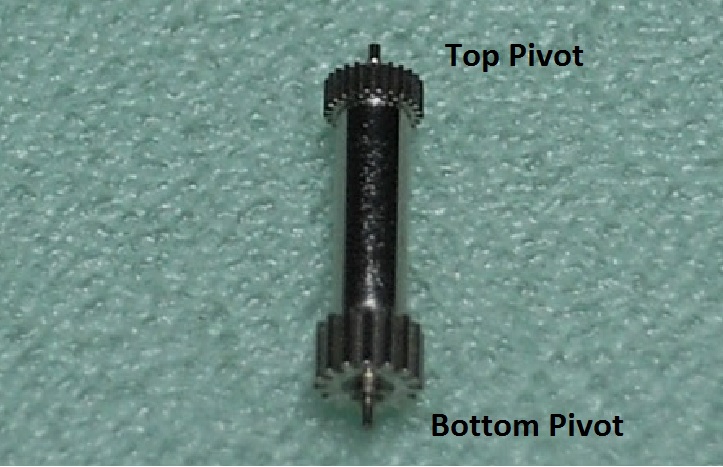
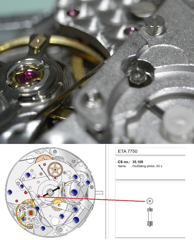
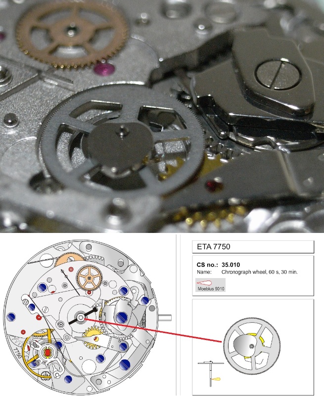
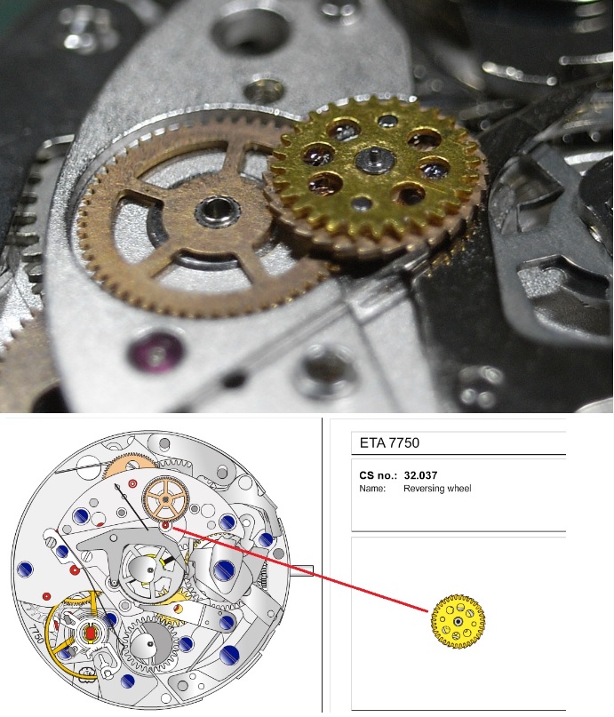
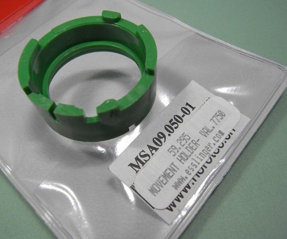
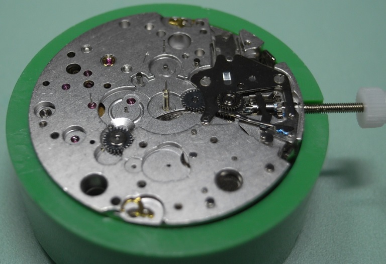
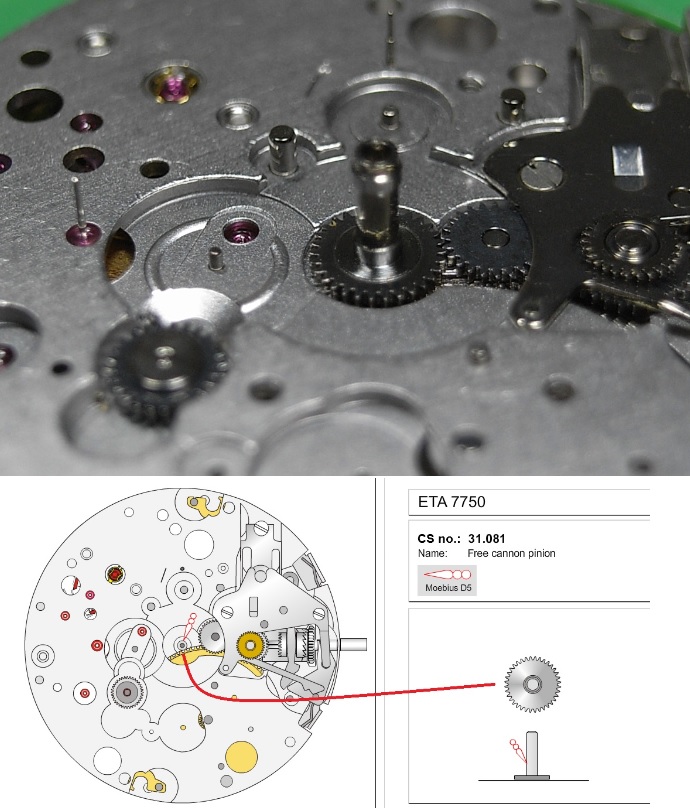
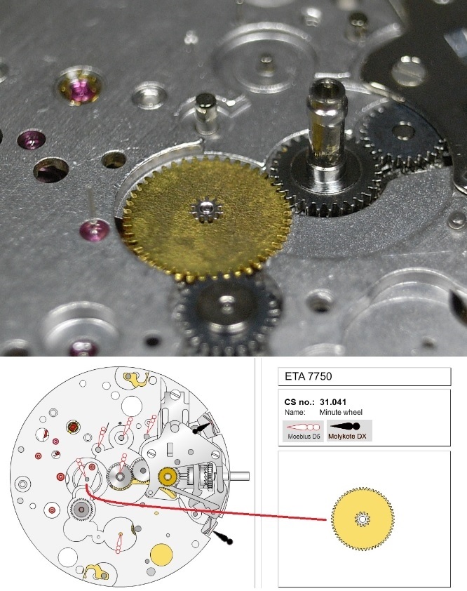
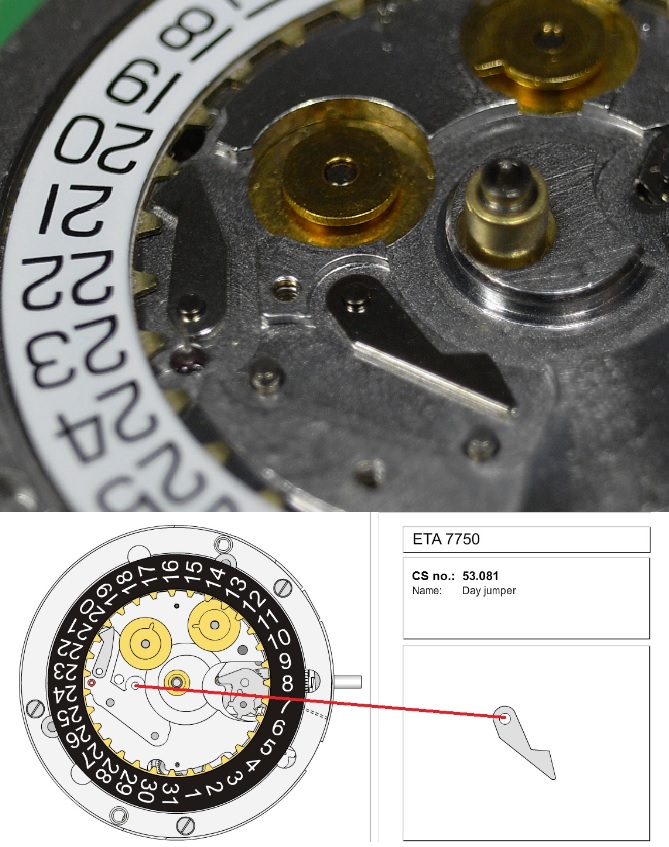
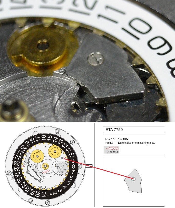
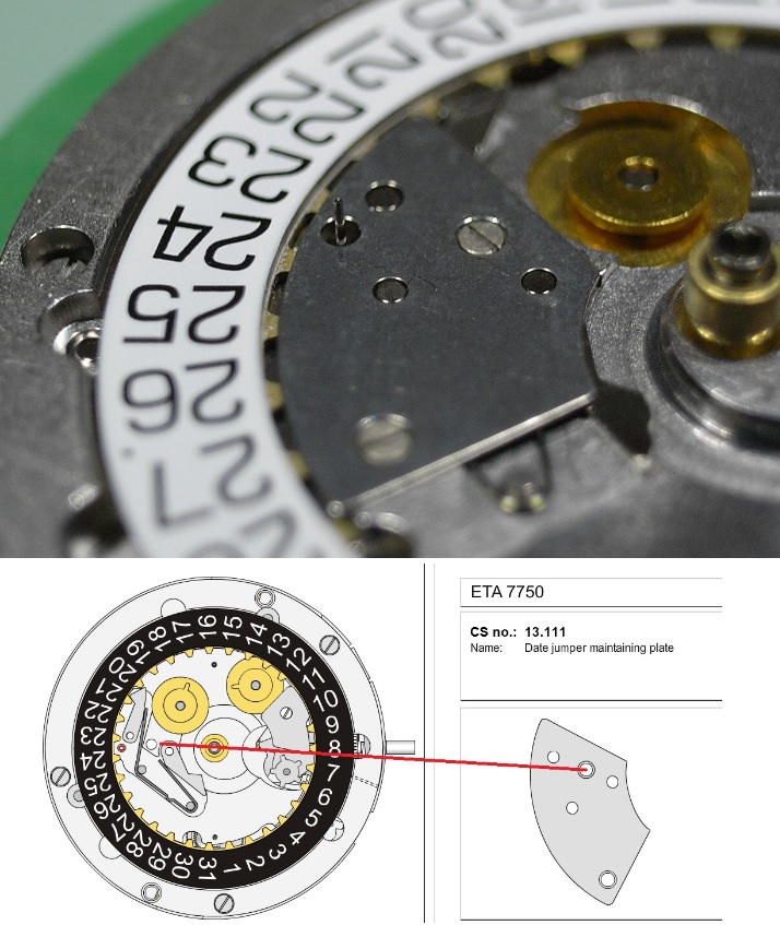
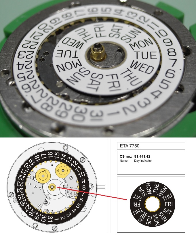
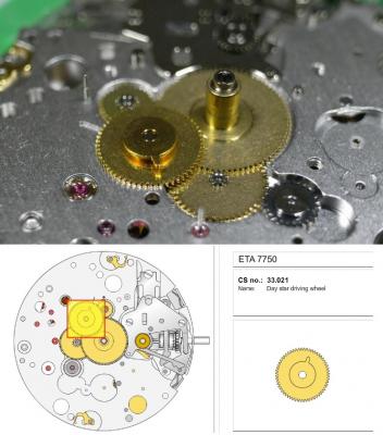
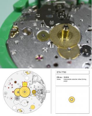
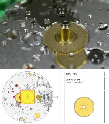
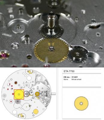
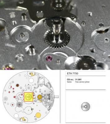
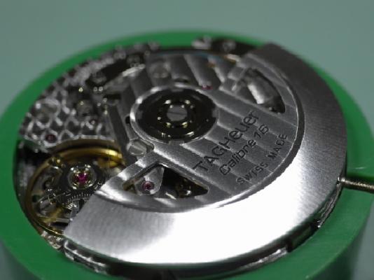
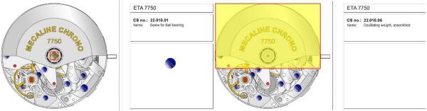
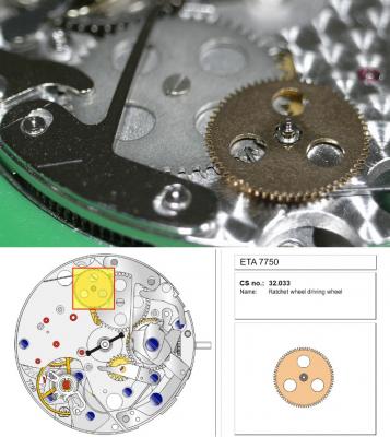
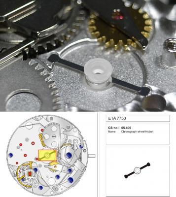
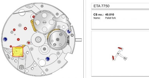
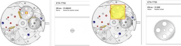
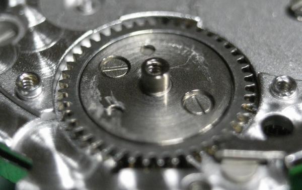
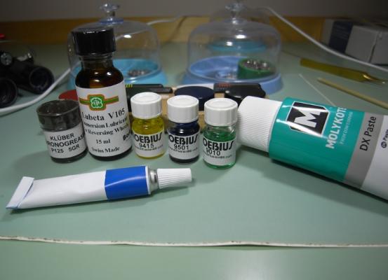
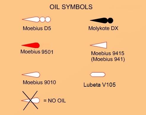
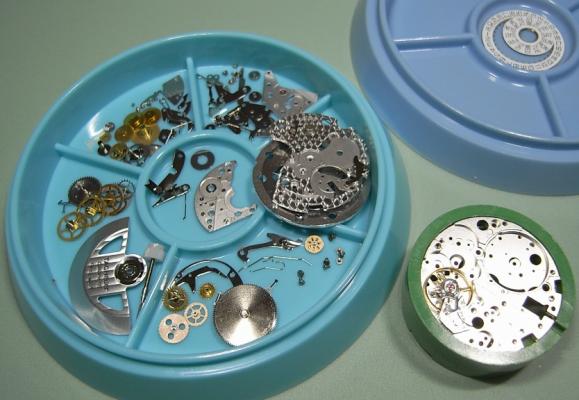
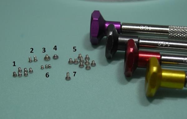
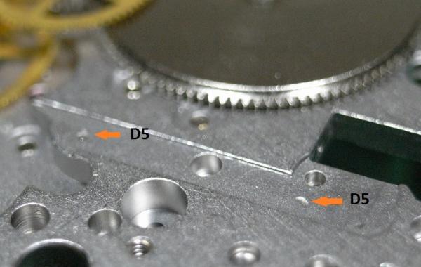
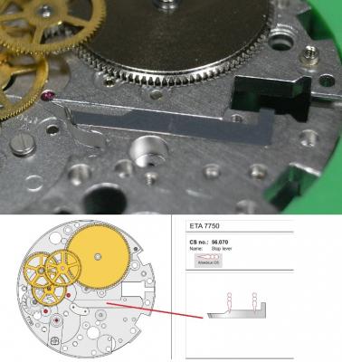
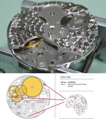
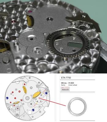
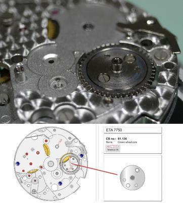
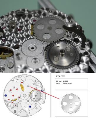
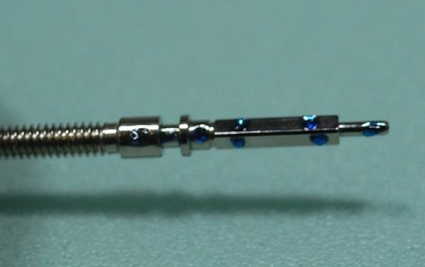
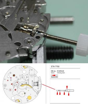
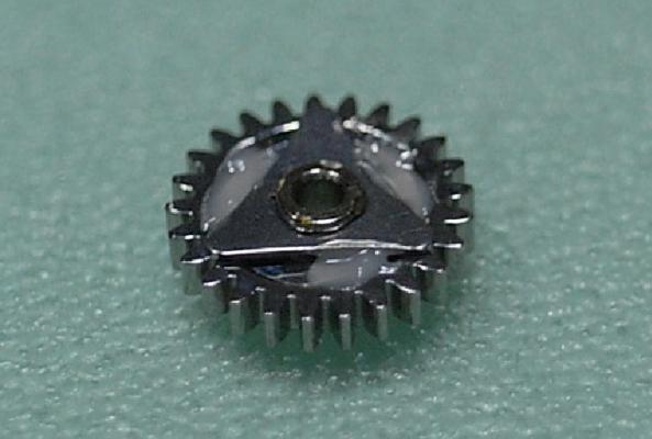
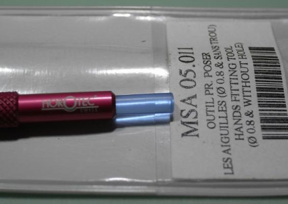
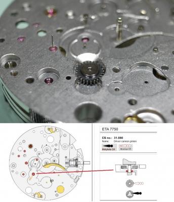
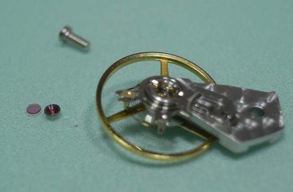
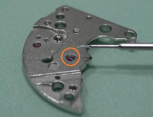
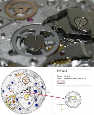
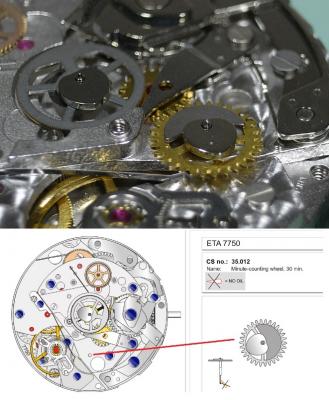
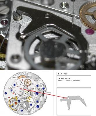
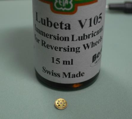
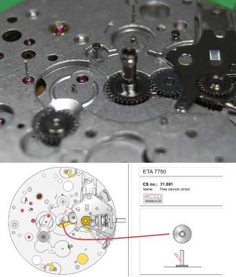
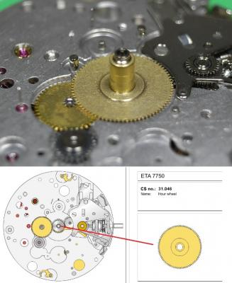
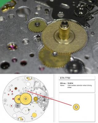
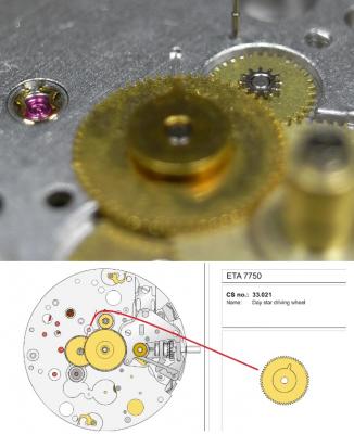
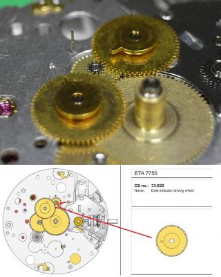
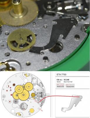
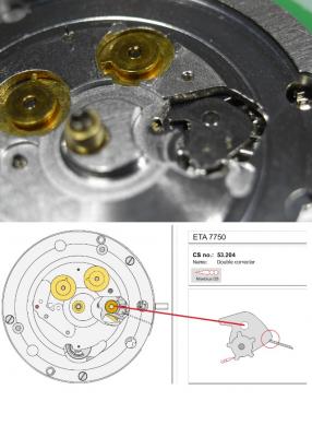
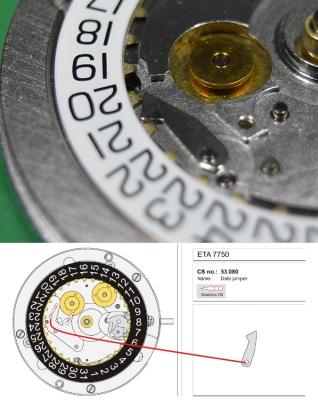
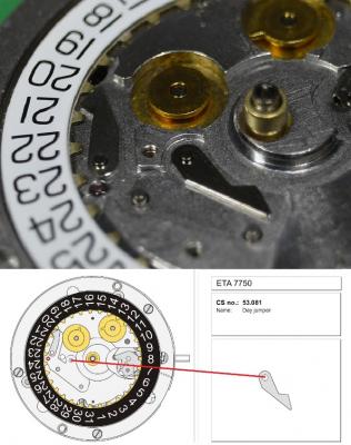
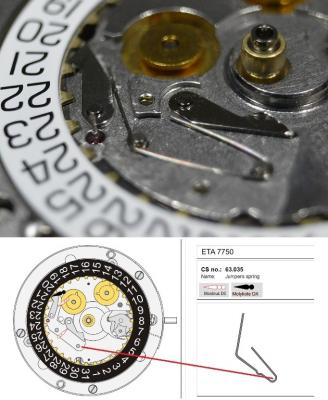
ETA 7750 Walkthrough Part 2 Assembly Now we come to assemble the movement. Here are the lubricants that will be used. Now nothing creates more discussion and controversy than which lubricants should be used on movements in various applications. This is how I approach it ... your choices may vary. The 7750 I am servicing here is a "Top Grade" ETA movement made for TAG, which would normally be cased with a display back. Because of this I will be using Molykote DX instead of Jismaa 125 or 9501 grease for areas that will be seen. As their lubricating qualities are very close, my choice of using Molykote DX is purely for ascetic reasons, as its less visible to the eye, then the bright colours of the 9501 and Jismaa 125. You will notice that Molykote DX is recommended in the 7750 PDF; yet on the SwissLab documentation it states to use Jismaa 125, so all these lubricates are recommended and safe to use. If this was a "Standard" or "Elabore" Grade movement with a full metal caseback, then I'd just go with the SwissLab recommendations, or 9501 for ease of servicing. With all that being said, here is the Lubrication Index for this walkthrough. Housekeeping Make sure your work area has been wiped down to remove any dust, and clear away any unneeded items from around your workspace. Inspect your Screwdrivers and Tweezers, and dress them up if needed. There is nothing worse than marring a screwhead, or have components ping from your tweezers because they need to be re-dressed. Put on some finger cots, or latex gloves. Personally, I use only one latex glove on my left hand, as any manipulation with my right hand will be done with my old trusty customized Dumont Brass #4 tweezers. NEVER touch cleaned parts with bare hands, this will leave prints and tarnish the finish over time. We begin with the parts fresh from cleaning. Try and arrange them in a logical order to start with, this will save you time fishing for parts later on. The 7750 has 7 types of screws, and you'll need 4 sizes of screwdrivers - 0.8, 1.2, 1.4, 1.5mm 1) Date Platform, Crown and Ratchet Wheel Screws 2) Setting Lever Spring Screws (Note the pointed ends) 3) Hammer and Cam Screws 4) Oscillating Weight Screw (Single Screw with the short thread) 5) Pallet Fork, Main Plate, Chronograph Plate, Automatic Work Plate Screws 6) Screws for the Jumper Maintaining Plates 7) Single longer screw for the Balance Cock I like to arrange all the screws in groups like this, that way they are quick to find, and mismatching screws can't happen. One more thing to note on this assembly walkthrough, is that I started by using the 7750 plastic movement holder. I quickly however changed to a Bergeon 4040 movement holder, and found this much better when it came time to fit the plates and align pivots to their jewels. I'd suggest you use the Bergeon 4040 holder right from the get go. Lets begin! Place the Barrel on the Main Plate Next is the Escape Wheel Followed by the Second Wheel, which has the long pivot for the sub-dial hand. The Third Wheel is next to be installed With the last wheel in the train being the Great Wheel. Place 2 small spots of D5 as shown, so the Stop Lever will have a smooth action. Install the Stop Lever. Now install the Barrel/Train Bridge. (1.4 Driver) Make sure all pivots are located correctly and the train is free spinning BEFORE tightening down. Once tightened down check end shake. Install the Crown Wheel Then the Crown Wheel Core and screw down (1.2 Driver). Install the Ratchet Wheel and screw down (1.2 Driver). Once this is done, using a 1.2 Driver, turn the screw on the Ratchet Wheel a 1/4 of a turn to add energy to the Mainspring, and check the free running of the train. Next is the keyless work. Lubricate the Winding and Sliding Pinion as shown below. Also add a spot of 9501 to the Main Plate where the Winding Pinion will come in contact. Be sure when installing he Sliding Pinion that it's seated properly on the Stop Lever Install the Sliding Pinion Install the Winding Pinion Lubricate and install the Stem. Next is the Driver Cannon Pinion. This is one area that needs a lot of lubrication, as it will bind and damage the movement if it becomes dry. To install the Driver Cannon Pinion I use a Horotec Hand Fitting Tool MSA 05.011 Once properly lubricated, install the Driver Cannon Pinion Before installing the Rocking Bar, lubricate the points on the spring. Install the Rocking Bar. Install the Setting Lever Install the Yoke. Place the Setting Wheel on it's post. Construct the Setting Lever Jumper with the Intermediate Wheel As noted above, the screws for the Setting Lever Jumper are the ones with the pointy threaded ends. Be sure to lubricate position points on the setting bar before you lever it into place. Install the Setting Lever Jumper / Intermediate Setting Wheel. The keyless work is now complete, check it is functioning correctly, then turn the movement over. Once the movement is turned over install the Pallet Fork. Then install the Pallet Bridge. Once the bridge is in place, give the mainspring a few winds and check the free movement of the Pallet BEFORE screwing it down (1.4 Driver) After tightening down check the end shake. Use 9415 on the Exit Pallet Stone to lubricate the escapement. Replacing the Balance and oiling the Incabloc Jewels is next. Place the Balance back onto the movement, checking that it's free running before tightening the screw (1.4 Driver). Once tightened check side shake and end shake is correct. Remove the Incabloc Jewel, and then remove the Balance. Note the longer screw that is used to secure the Balance Cock. Cleaning them carefully by soaking in a container with Lighter Fluid ... I use Zippo Fluid. Once clean, dry the Balance and Incabloc Jewel and place a drop of 9010 on the Jewel as shown below. Make sure it covers at least 1/3 to 1/2 of the jewel, without the oil touching the sides of the jewel. Give the movement several winds to add some power to the Mainspring. Replace the Balance back on the movement and refit the Incabloc Jewel. Check that the Balance is oscillating freely. Then repeat the process for the jewel only on the Main Plate. Next to be installed is the Hammer Cam Jumper. Here is my method for installation. Place the Hammer Cam Jumper into position, turning it clockwise to lock it into the slots. Then place the Chronograph Cam on it's post, so that it rests on top of the cam jumper ... as shown below. Then while holding the arm of the cam jumper back, seat the Chronograph Cam into position and affix the screw (1.4 Driver) Install the Switch Insert the Operating Lever Spring, 2 Functions. Make special note of the orientation of this spring, as it will fit in both directions; but only one way is correct. Without lubricating, install the Minute-counter Driving Wheel, 30min. Install the Lock, 2 Functions, and screw down (1.4 Driver) Before installing the next item, which is the Operating Lever, 2 Functions, be sure to lubricate the hinging point from underneath with D5. Then install the Operating Lever, 2 Functions. Be sure that the spring arm of the Lock is out from under the Operating Lever and screw down (1.4 Driver). Place D5 into the little slot opening in the top of the hinge point. Install the Chronograph Wheel Friction. Install the Ratchet Wheel Driving Wheel Before placing the Chronograph Bridge onto the movement, you need to oil the jewel circled in the image below with D5 After oiling that jewel install the Chronograph Bridge. Next, place the Reduction Wheel into the hole in the Chronograph Bridge. Note that there is no post to locate this wheel, as it's on Automatic Device Bridge which will be installed later. The next item is the Oscillating Pinion which seems to cause people a lot of frustration. Here's my method to install it. Firstly, be sure of the correct orientation, as shown below. Pull the Crown out to the third position to engage the Stop Lever and hack the movement. Keep the movement in this hacked position until the Automatic Device Bridge is installed. Then install the Oscillating Pinion and seat it into it's lower jewel. You'll know you've done this correctly when it sits up straight and centered in the slot ... as shown in the image below. By taking your time and getting it well seated you will have less trouble when installing the Clutch later on. However, before we install the Clutch and Automatic Device Bridge, there are a few wheels and a hammer that need to be installed. Install the Chronograph Wheel, 60s, 30min Install the Minute-counting Wheel, 30 min. Install the Clutch 60s, 2 Functions. The Clutch needs to slip underneath a small click spring for the Reversing Wheel, so be careful not to bend and damage this spring. Then gently lift the arm of the Clutch over the Oscillating Pinion. Yes, it's a delicate job, but with a steady hand, patience and well dressed tweezers, it's not too hard. Before we install the Reversing Wheel, we need to lubricate it. The product needed is Lubeta V105, which is an immersion, or dip, lubricant. Simply hold the Reversing Wheel with tweezers and dip it into the solution. Then allow it to dry, which takes about 10 minutes. This leaves behind a waxy type lubricant that has impregnated deep into the wheel. Once dry, install the Reversing Wheel Install the Hammer, 2 Functions. Make special note of the orientation of the cam to the hammer. You may need to rotate the cam into this position before you fit the hammer. Now it's time to install the Automatic Device Bridge. Make sure all wheel pivots are correctly located in their jewels before tightening down (1.4 Driver) Pay close attention that the Oscillating Pinion is still seated correctly in it's pivot hole on the Clutch. One other troublesome operation for people is installing the Clutch Spring. This is my method of installation. Slide the long arm of the spring into it's position until the shorter end is touching the automatic bridge. Then with your tweezers grab the point illustrated below and lift it over the locating screw. Once over the screw, push it forward and until the loop is seated on the locating screw. Lastly, install the Hammer Spring, 2 Functions. Now you can un-hack the movement by pushing the Crown into it's winding position. Check that the Oscillating Pinion is being driven by the movement. Check the Chronograph functions are engaging and dis-engaging correctly by operating the pushers. Once you are satisfied all is well, turn the movement over. Now we come to the calendar work. For this I place the movement back in the Horotec 7750 plastic holder (MSA 09.050-01) Install the Free Cannon Pinion Install the Minute Wheel. Install the Hour Wheel Install the Intermediate Calendar Driving Wheel Next the Day Star Driving Wheel It is most important that you line up the driving tooth of this wheel with the marker on the Main Plate. If the wheel appears to be half a tooth off proper alignment, bring the Crown out to the hand setting position and adjust so the tooth lines up perfectly. Failure to do this will result in improper synchronization of the day and date. Install the Date Indicator Driving Wheel. This time you line up the wheel's driving tooth with the post for the Intermediate Calendar Driving Wheel. Failure to do this will result in improper synchronization of the day and date. Install the Hour-counting Wheel Install the Hour Hammer Install the Hour Hammer Operating Lever Install the Hour Counter Lock Install the Hour Hammer Spring Place on the Date Platform, and secure down (1.2 Driver) Install the Double Corrector, making sure the spring is correctly positioned. Place on the Date Indicator. Install the Date Jumper. Be sure you have selected the correct jumper, as the Day and Date Jumper are not Identical. Install the Day Jumper Install the Jumper Spring. Place on the Date Indicator Maintaining Plate and screw down (0.8 Driver) Place on the Date Jumper Maintaining Plate and screw down (0.8 Driver) Fit the Day Indicator, and test the function and timing of the Day/Date Turn over the movement to fit the last item. The last item to fit is the Oscillating Weight. Gently place it on the movement, check it's meshed properly and then screw down (1.5 Driver) Service on the ETA 7750 is now complete, and adjusting the timing of the movement is the only operation left. I hope this has been of interest and helps those wishing to tackle this caliber. I'm sure, as I did, that you'll find it a fun and reward movement to service.


 1 point