Jump to content

Longines 291(?) help


Chopin

Recommended Posts

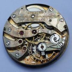
I have the opportunity to buy a lovely Longines watch but I'd like to know if this is an easy fix. Seller only says that a screw is missing from the oscillating weight and that that's why it's not installed on the movement.

I'm not sure how this one works and how it stays on the movement and I also feel like I see a screw on the weight in the picture. Could someone shed some light on this ? Should the weight have another component that goes into the slot or is just a screw necessary ?

There is a screw on the weight near the movement and I see it in the picture but I assume that's not what we're talking about...

Also, is this even a cal 291 or something else ?

Is the circle in the bag, around the weight, even part of all this ? Could it be some sort of a ring for the movement ? Doesn't seem like it...

20170923_094937.jpg

Edited by Chopin
Link to comment
Share on other sites

It is a calibre 291 the rotor sits on a post at the centre of the movement and the screw on the rotor is used to secure it to the post. It is probably the rotor post that has broken, these are listed as obsolete on the cousins web site, it is a common problem with this movement I dont know if any other supplier would hold this particular part. The ring looks like a tension ring from a watch crystal and is not a part of the movement such as a movement spacer ring as this one is held in place with clamps

  • Thanks 1
Link to comment
Share on other sites

9 minutes ago, wls1971 said:

It is a calibre 291 the rotor sits on a post at the centre of the movement and the screw on the rotor is used to secure it to the post. It is probably the rotor post that has broken, these are listed as obsolete on the cousins web site, it is a common problem with this movement I dont know if any other supplier would hold this particular part. The ring looks like a tension ring from a watch crystal and is not a part of the movement such as a movement spacer ring as this one is held in place with clamps

Is this post a separate part that gets screwed/attached onto the movement and then you attach the weight or is it attached to the weight itself ?

It's most likely hard to find so only solution would be a donor movement...

Edited by Chopin
Link to comment
Share on other sites

Yes the post is a separate part that is secured with two screws from the under side of the bridge, why not ask for clarification from the seller as to what part is missing or broken if its just one of the screws that holds the rotor post in place it should be easy enough to find a suitable one to use but if it is the post that broken then you will have trouble finding one as you say the way to go would be a donor movement but that may start to make the good price look a little less appealing

  • Like 1
Link to comment
Share on other sites

Seller doesn't seem knowledgeable. I got another picture from him. Is that the post ? Not the best picture sadly...

20170923_123831.jpg

I think I can see a screw and a missing one... Am I wrong ? Do you have to detach it from the weight to install it onto the movement ? I see no other way...

Edited by Chopin
Link to comment
Share on other sites

1 hour ago, Chopin said:

I have the opportunity to buy a lovely Longines watch but I'd like to know if this is an easy fix. Seller only says that a screw is missing from the oscillating weight and that that's why it's not installed on the movement.

I'm not sure how this one works and how it stays on the movement and I also feel like I see a screw on the weight in the picture. Could someone shed some light on this ? Should the weight have another component that goes into the slot or is just a screw necessary ?

There is a screw on the weight near the movement and I see it in the picture but I assume that's not what we're talking about...

Also, is this even a cal 291 or something else ?

Is the circle in the bag, around the weight, even part of all this ? Could it be some sort of a ring for the movement ? Doesn't seem like it...

20170923_094937.jpg

It's a real pity because looking the movement it is in really good condition apart from the screw or post has been broken. The 291 is obsolete so its up for sale.

  • Like 1
Link to comment
Share on other sites

No the post sits directly in the middle of the movement and is not part or the rotor itself. If the watch is very cheap I would take a punt and factor in the cost of a donor movement if its only slightly cheaper than a  runner walk away.

  • Like 1
Link to comment
Share on other sites

1 minute ago, wls1971 said:

No the post sits directly in the middle of the movement and is not part or the rotor itself. If the watch is very cheap I would take a punt and factor in the cost of a donor movement if its only slightly cheaper than a  runner walk away.

If it is just the post it should be possible to make one,  if you have a lathe that is !!!

  • Like 1
Link to comment
Share on other sites

So, basically, there should be another part between the movement and the rotor right ? I was hoping that the thing on the underside of the rotor might be it but I guess it's not... Wish I could find a schematic of the movement and see what that part looks like...

No lathe. Not that advanced I'm afraid...

Edited by Chopin
Link to comment
Share on other sites

Is it this one below ? I keep finding it listed for other calibers so I guess it might be interchangeable... Very pricey sadly.

This part should replace the one marked axle by @wls1971 right ? I'm assuming you remove the top plate, install the new one, put the plate back and then screw it in place with those 2 screws and then the rotor... ?

image.thumb.png.063b2dddc4b7168151160c03f226d33a.png

I wonder if there's a chance that it might not be broken and it's just missing the screws...Only close up shot I have.

20170923_094947.jpg

Edited by Chopin
Link to comment
Share on other sites

25 minutes ago, rogart63 said:

Is the 290 post the same as the 291. I now where you can find one. Send me a PM and i can give you the contact. 

Yes calibre 290 no date calibre 291 addition of date at either 12 o'clock or at 3 o'clock 

  • Like 1
Link to comment
Share on other sites


  • Recently Browsing

    • No registered users viewing this page.
  • Topics

  • Posts

    • It looks like the canon pinion function is part of this great wheel. The pinion nearest the clip runs the minute wheel on the dual side. The pinion nearest the wheel is driven by a small wheel from under the setting lever cover plate that engages in hand setting position.    So when assembled the crown was driving the whole great train. Does this mean the pinions are too tight? Should I attempt to disassemble this great wheel and lubricants?
    • Picking up this side-tracked post again as I just removed a balance staff of a 1920's Omega (35,5L-T1) I was impressed by the way @Delgetti had his setup when he had to change out a balance-staff (https://www.watchrepairtalk.com/topic/28854-new-balance-staff-not-riveting-to-balance/page/2/#comment-244054 Not only that, but also the idea of removing the seat first before punching the staff out from the seat-side, avoiding the whole discussion of the rivet yes/no enlarging the hole. I didn't have the fancy clamps & tools Delgetti has, so I used my screw-head polishing tool. Initially I used #1500 grit diamond paste on the steel wheel, which kinda worked, but very slow. I changed to #800 grit diamond paste, which worked better, but still slow. Then I glued #240 sanding paper to the steel disk; That worked and the disk was hand-driven. Once close to the balance wheel, I took the sanding paper off and continued with #800 diamond paste. One can only do this when the balance wheel sits true on the staff and has no "wobble". I went on grinding until I saw some diamond paste on the rim of the balance wheel. This was as far as I could grind and it seemed that there wasn't much left of the seat. Carefully, with my staking set, I knocked the staff from the seat-side out. Turns out that the thickness of the seat left, now a small ring, was only 0.1mm. The balance wheel hole is in perfect shape and no damage done to the wheel at all. Of course, if the wheel has a "wobble" or isn't seated true on the balance staff, you can't get as close and there will be more left of the seat. In my case, it all worked perfect 🙂 I'm very happy how this worked for me 😊  
    • As is tradition, one step forward, two steps back. Got the board populated and soldered into place without any issues.   But no hum. So I started testing the coils with an ohmmeter. I got 5.84k ohms across D1 (from red to red in the picture below), which is as expected. But I'm getting an open circuit for the other drive coil and feedback coil, D2 and F1 (from green to each of the two yellows).   Since the movement was working with my breadboard setup, it implies I somehow broke the connection between the coils and the solder lugs. They're all the way at the bottom of the lugs, but maybe the heat migrated down and broke the connections? I guess it's possible it happened while cleaning the flux off, but I used a soft artist's brush and isopropyl alcohol. I did a lot of high magnification examination, and I don't see any issues, but let me know if you see anything I missed or if you can think of anything else I should check.
    • 1947 NOS Ambassador 'C'. Actually, the case came without the movement so the movement isn't NOS, but she sure is pretty.
    • Hi attached is the AS 20XX. Service sheet although there is no 2063 mentioned it may be of some use to you AS_AS 2060,1,2,6,4,6.pdf
×
×
  • Create New...