Jump to content

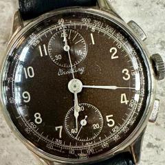
Chinese Timegraphers


Recommended Posts

1 hour ago, xyzzy said:

Keep in mind that the displays on the power supply have two modes.  One shows the max values you are setting, the other shows the actual values as it supplies power.  You can't get both current and voltage to be specific values, it would violate Ohm's law.  You get one, then the other is forced based on the resistance of the load.  You set maximums for both, but only one max, V or I, will be reached and the other will be whatever V = I * R produces based on the load's R.

So maybe the power supply needs to have its outputs off to show the set points?  Most seem to let you adjust while on, and the digits will flash to let you know you are in set mode rather than measured mode.

If the power supply isn't connected, it should read 0 A when on.  How can it supply current when there is no circuit?

My power supply works in either Constant Voltage or Constant Current.  I was trying to set the current to 0.5A, then adjust the voltage.

To set the current, you first set the voltage to 3-5V, then turn the current knobs to zero, and short the output terminals. Then adjust the current to the value you want.  Problem is, I can't get it to show any current, it just switches back to Constant Voltage mode. There's a known problem with this power supply blowing the MOSFETS. It has 4 and I was trying to figure out how to test them. I found this link https://electronicsbeliever.com/how-to-know-if-mosfet-is-defective/

I don't know if these tests are good/bad/useless, or if there are any others you could point me to?

Link to comment
Share on other sites

On 1/29/2023 at 6:24 PM, Kalanag said:

My test result: The LED doesn‘t light up if the device is just connected to an USB charger. Connected to my PC the LED lights up.

I measured the voltages according to @mikepilk

The results (just) on the USB side of the board are very different! The REGV output of the CM108 has the correct voltage of 3,3V where the faulty board just has 0,64V.

2DAA9C1B-8F7F-4898-8DC4-6570076E5070.thumb.jpeg.52f8d7fedf7eb1417bebf726e722da73.jpeg


Thanks Kalanag,

Do you know anything about the SPK pins? Since this is a USB audio interface, maybe you could play audio from PC?

One can potentially turn this into a beat amplifier (with a speaker or headphones attached).


Link to comment
Share on other sites

1 hour ago, TGX said:

One can potentially turn this into a beat amplifier (with a speaker or headphones attached).

I‘m sure that is feasible. „SPK“ should mean „speaker“.

CC565D19-147C-49B8-A3C6-854EC2AFB569.jpeg

20 hours ago, mikepilk said:

The article does say MOSFET testing, and starts with the diodes. I assume they are part of the MOSFET? Looks like 2 of mine have failed.

https://electronicsbeliever.com/how-to-know-if-mosfet-is-defective/

MOSFET testing (video)

Edited by Kalanag
Link to comment
Share on other sites

On 1/29/2023 at 6:53 PM, Kalanag said:

You are right! But if the capacitor is o.k. the C108 is shot 😞

My new meter has arrived, which can measure Capacitance. Can this be used to check C1 in situ, or does it only work with 'free' components - there's a little gizmo to sit them in.

It can also measure Hz, diodes test,  and transistors (hFE), if that's of any use.

20230131_150551.thumb.jpg.06066c9c5c028c424cdad4bd0a335acd.jpg

Link to comment
Share on other sites

6 minutes ago, Kalanag said:

My C1 reads 3,8 microfarad constantly! It never drops to zero. I‘m not sure your C1 is fine!

IMHO...those caps never go bad...they just don't.  It is two metal plates separated by a bar of ceramic.  If it is not a dead short or an open circuit...it is just fine. My bet is that the chip is bad.

Link to comment
Share on other sites

4 hours ago, Kalanag said:

I‘m sure that is feasible. „SPK“ should mean „speaker“

I've already seen a variation of this microphone where it does have the speaker output jack. But is it connected to the large IC that in this case isn't working? if you want to use it for beat amplifier just connected to the output of the ICU of the input is connected to because that will work just fine. Is actually designed for a crystal input and driving a speaker output so it works perfect for making a beat amplifier you don't need the rest of this at all

Link to comment
Share on other sites

7 minutes ago, JohnR725 said:

I've already seen a variation of this microphone where it does have the speaker output jack. But is it connected to the large IC that in this case isn't working? if you want to use it for beat amplifier just connected to the output of the ICU of the input is connected to because that will work just fine. Is actually designed for a crystal input and driving a speaker output so it works perfect for making a beat amplifier you don't need the rest of this at all

The speaker output is connected to the CM108 line out pins 30 (left) and 32 (right) via two (missing) capacitors.

33 minutes ago, LittleWatchShop said:

IMHO...those caps never go bad...they just don't.  It is two metal plates separated by a bar of ceramic.  If it is not a dead short or an open circuit...it is just fine. My bet is that the chip is bad.

You are right most likely. But I don’t wanna give up yet 😉

Link to comment
Share on other sites

10 minutes ago, Kalanag said:

The speaker output is connected to the CM108 line out pins 30 (left) and 32 (right) via two (missing) capacitors.

So in other words you wire it direct up to the LM 386 and use it as a beat amplifier

Or even take the output of the LM 386 and run that into the computer input. Which is basically what the original version of this one did it anyway and could probably still powered off the USB port. Only usable to do if your large IC seems to not be functioning otherwise just use it as the way it is.

Then as far as the beat amplifier goes you don't need the output jack because the computer sound will do the same thing. Just be careful not to increase the volume too much because I found it was very sensitive to feedback the microphone is way too sensitive to audio noise around it including the computer speaker outputting whatever you're picking up.

Link to comment
Share on other sites

55 minutes ago, JohnR725 said:

I've already seen a variation of this microphone where it does have the speaker output jack. But is it connected to the large IC that in this case isn't working? if you want to use it for beat amplifier just connected to the output of the ICU of the input is connected to because that will work just fine. Is actually designed for a crystal input and driving a speaker output so it works perfect for making a beat amplifier you don't need the rest of this at all

image.png.fd1ba9f25e8f8c5120bef23fa43f4e6a.png

Link to comment
Share on other sites

33 minutes ago, LittleWatchShop said:

image.png.fd1ba9f25e8f8c5120bef23fa43f4e6a.png

That I'm familiar with as it's currently sitting in front of me were it's been for the past couple of whatever to remind ma'am supposed to make a circuit board to go with it.

That's not what I was talking about I've already seen a modified version of the current design were somebody added in the speaker output so right next to the little USB connector is a green connector for something. But unfortunately all the ones I'm currently looking at don't have it so I have no idea where they saw that previously

Link to comment
Share on other sites

22 minutes ago, mikepilk said:

With the probes reversed it reads 0.0

O.K. so the first measurement was done right. To be sure whether the capacitor is faulty or the CM108 respectively other peripherals it has to be desoldered. But first I would measure the capacitors that xyzzy mentioned in his post at 5:05 yesterday.

Link to comment
Share on other sites

2 hours ago, Kalanag said:

O.K. so the first measurement was done right. To be sure whether the capacitor is faulty or the CM108 respectively other peripherals it has to be desoldered. But first I would measure the capacitors that xyzzy mentioned in his post at 5:05 yesterday.

I assume that capacitors must be tested with no power to the board, and that they should give a steady value?

Link to comment
Share on other sites

1 hour ago, mikepilk said:

I assume that capacitors must be tested with no power to the board, and that they should give a steady value?

Yes.  However, when testing a capacitor "in circuit" there is the possibility of energizing other active components which will interfere with the reading.

Again...testing surface mount capacitors is truly a distraction.

The chip?

4 hours ago, JohnR725 said:

That's not what I was talking about

Same chip...same output. 

Link to comment
Share on other sites

12 hours ago, LittleWatchShop said:

Yes.  However, when testing a capacitor "in circuit" there is the possibility of energizing other active components which will interfere with the reading.

Again...testing surface mount capacitors is truly a distraction.

From @xyzzy

Quote

If the current powering the board is reading new zero, one might think it can't be a short, but that might not be the case.  The CM108 regulator might automatically shut down if shorted.

Possible shorts in REGV are C1 (C5 in the C108 example schematic)

I'm checking the capacitors and getting odd results with C4,C5,C6 and C10. So I tried them in beep mode, and can get them to beep with the probes connected in either direction. Is that a faulty cap, or could it be a faulty C108? 

C4-6 look to all be connected to the same line, so it may only be one? 

Edited by mikepilk
Link to comment
Share on other sites

37 minutes ago, mikepilk said:

I'm checking the capacitors

LittleWatchShop is right, this type of capacitor is exceedingly unlikely to fail and when they do, they tend to leave a crater. Also, testing them in-situ is at best a confusing exercise. You have no idea what the rest of the board is doing so you can't trust your readings.

My money is on the IC having failed.

Edit: the sane thing to do would obviously be to buy another board, but none of us would be here if we were entirely sane and didn't like to tinker. You could acquire a replacement IC and a hot air station (doesn't need to be gold plated, most anything off ebay will do) and try to replace it?

Edited by fellerts
Link to comment
Share on other sites

22 minutes ago, fellerts said:

LittleWatchShop is right, this type of capacitor is exceedingly unlikely to fail and when they do, they tend to leave a crater. Also, testing them in-situ is at best a confusing exercise. You have no idea what the rest of the board is doing so you can't trust your readings.

My money is on the IC having failed.

Edit: the sane thing to do would obviously be to buy another board, but none of us would be here if we were entirely sane and didn't like to tinker. You could acquire a replacement IC and a hot air station (doesn't need to be gold plated, most anything off ebay will do) and try to replace it?

Ok I'll give up and bin it. I'm loathe to buy another and wait for weeks, when the same thing may happen - it only lasted for about an hour. At least I've had some fun trying to fix it. 

Now I've got a new meter, and plenty of time, I'm going to carry on and learn about testing electronics, so I'll know what to look for next time. I've got a long way to go. I need to try and fix my power supply. Apparently the MOSFETs are prone to fail - I spotted two on a large heat sink. One tested OK, testing the other made no sense. After lots of head scratching I Googled the very faint number - turns out to be a "diode array". It looks identical to the MOSFET along side it!  These electronics people don't make it easy. 

Link to comment
Share on other sites

Join the conversation

You can post now and register later. If you have an account, sign in now to post with your account.
Note: Your post will require moderator approval before it will be visible.

Guest
Reply to this topic...

×   Pasted as rich text.   Restore formatting

  Only 75 emoji are allowed.

×   Your link has been automatically embedded.   Display as a link instead

×   Your previous content has been restored.   Clear editor

×   You cannot paste images directly. Upload or insert images from URL.


  • Similar Content

  • Recently Browsing

    • No registered users viewing this page.
  • Topics

  • Posts

    • Post some pictures , some good close ones of the parts you've described. 
    • Ive never used epilame H only information i have read and mentally stored about it mostly from Nicklesilver here and elsewhere ( the fork horns thing ), maybe the residue powder that is removed has some grinding effect ? So probably a good idea to limit its application areas to only the absolute necessary. Yes as far as i know epilame rubs off relatively easy, the technique of running the watch to make a groove through it first in the pallet stones where the lubrication is then placed. This i understand creates the barrier for the lube to sit up to. If i can find a good balance of pros and cons of its use then thats one process i can avoid by using a thixotropic lube on the stones. The epilame i would say allows for a more fluid lubrication to be used that would increase amplitude on low beat movements. The stearic acid powder is extremely cheap, the problem is the fuming process to coat parts, is not selective , the whole part has to treated in this method. If epilame residue can cause wear then thats not good, if I remember the conclusion was not proved entirely just a general assumption between watchmakers. The thread is out there somewhere, the same discussion is also old on a facebook group. Ive never used epilame H only information i have read and mentally stored about it mostly from Nicklesilver here and elsewhere ( the fork horns thing ), maybe the residue powder that is removed has some grinding effect ? So probably a good idea to limit its application areas to only the absolute necessary. Yes as far as i know epilame rubs off relatively easy, the technique of running the watch to make a groove through it first in the pallet stones where the lubrication is then placed. This i understand creates the barrier for the lube to sit up to. If i can find a good balance of pros and cons of its use then thats one process i can avoid by using a thixotropic lube on the stones. The epilame i would say allows for a more fluid lubrication to be used that would increase amplitude on low beat movements. The stearic acid powder is extremely cheap, the problem is the fuming process to coat parts, is not selective , the whole part has to treated in this method. If epilame residue can cause wear then thats not good, if I remember the conclusion was not proved entirely just a general assumption between watchmakers. The thread is out there somewhere, the same discussion is also old on a facebook group. If its a potential problem for amateurs to use then i would prefer not to take the risk .
    • Following on from my question about identifying screws in the AS2063 movement that basically fell out of the case in bits, I’m pleased to report that I’ve got it all back together, and the movement is running pretty well.    But… There’s something wrong with the keyless works and hand setting. It’s fine in winding and quickset date position - these work - but in hand setting position winding the crown turns the whole gear train.  I don’t really understand how it’s meant to work. It doesn’t have a traditional friction fit cannon pinion.  The second wheel is unusual with a pair of smaller pinions on it, which seem to interact with the barrel and the motion works.    Could this be the problem? I must admit I just cleaned it and popped it in place when reassembling the gear train. I’ve lubricated the pivots but didn’t do anything to the extra bits on the second wheel.    Does this make sense and is anyone able to figure out what I’m doing wrong? Thanks in advance, as always.    ETA - the parts list calls it the Great Wheel, not second wheel. 
    • You're thinking metal to jewel in general I guess. Maybe it would be a good idea to peg the pallet staff jewel hole on the main plate after the epilame treatment. I think that could work as it is my impression that the epilame doesn't sit very hard, but I could be wrong about that so feel free to educate me. I didn't remember that 9501 was thixotropic (thanks for the link). That would mean it's even runnier during impact (lower viscosity) so perhaps it's time I get some fresh grease as mine seems a bit too runny. What I have seen is a whitish surface after washing but it goes away if I scrub the surface with a brush in a degreaser (Horosolv). I don't think it embeds itself in the metal but sticks very hard to the metal. I don't worry too much about the cleaning solution. I just want perfectly clean parts and my solution can be replaced for little money (ELMA RED 1:9). Anyway, I quite often need "to strip back and rebuild" and scrubbing parts by hand isn't exactly the most stimulating part of a service. Just got confirmation that Moebius 9501 has a lower viscosity (68 cSt at 20° C) than 9504 (305 cSt at 20°). The viscosity of Molykote DX is 285-315 cSt at -25° to +125° C. I was surprised to see that the viscosity of Moebius 9010 (thin oil!) is higher (150 cSt at 20°) than my 9501 grease!
    • I’ve had a couple movements where it is clear the previous watchmaker was diligent with lubrication but the old epilam had turned to a fine white powder covering the pallet fork and keyless parts, which can’t be good for parts. I’m spare with epi since I don’t know how long it takes to degrade to that state…
×
×
  • Create New...