


-
Recently Browsing
- No registered users viewing this page.
-
Topics
-
-
Posts
-
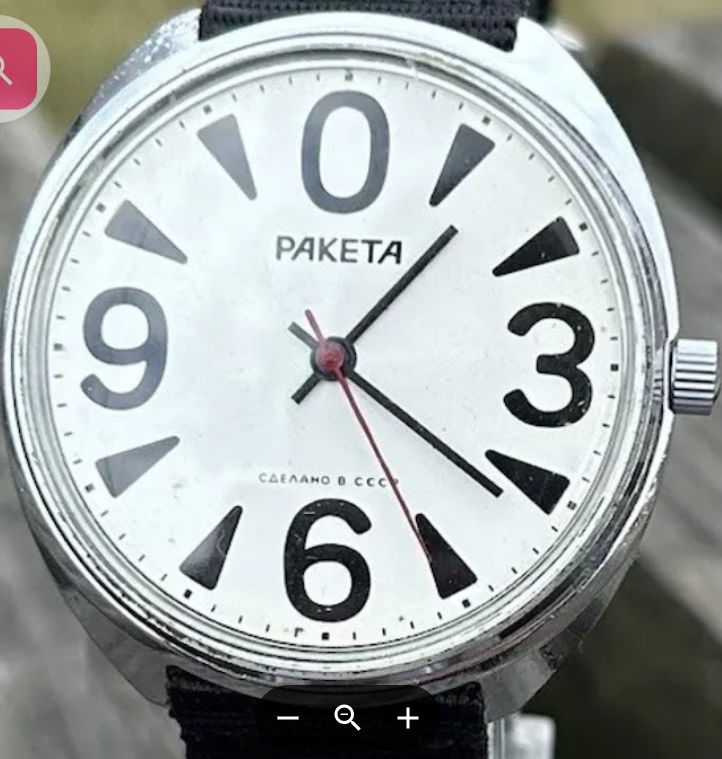
 Just arrived today with the case a little worse for wear so will probably just polish it back to the steel
 -
 I must be going nuts !! I checked the parts list to get a part number and see that there is no screw shown. Only a rotor assembly. I checked the rotor I removed and the screw is part of the assembly. What a stupid error Regards to all, Dave
 -
This would have been seen before the fork and balance were even fitted if you carried out a test on the train wheel as a matter of course.
-
 With the amphibia there's also the gasket in the screw-in crown. If memory serves a correct seal for the back of the case is tricky to find as well, but maybe that's because mine are vintage. The newer cases are larger I think.
 -
 As others have pointed out we discussed this subject in great lengths multiple times on multiple discussion groups. Then we have a subject that has too many variables and generalizations that make all the different things seem like one common removing staffs when it's not. There are variety of balance wheels specifically designed to be hard enough to withstand knocking or pushing a staff out. Rolex has one that the only way the staff is coming out is by pushing it out enough pressure is applied the river breaks with a very satisfying pop. This is because they hairspring cannot be removed until the staff is pushed out through. Then of course Rolex has a nice set of tools just for this purpose. A variety watch companies like Elgin made a balance wheels specifically designed to be hard enough to withstand knocking the staff have. For instance that principle is applied with jeweling tool you mention and here's the complete article down below that explains the procedure. Then of course there are variety watch companies Elgin And Hamilton that specifically designed balance staffs designed to be knocked out because the riveting shoulder is supposed to break. That of course would be the original staffs and probably the aftermarket do not have such features. One of the problems with all of these tools would be the balance staff itself and of course whatever the balance wheel is made of. Personally I like the rule of if you're knocking the staff out and you gently tap with the hammer and it doesn't just pop out then you do not drive it out you do have to use a lathe. Because for variety of reasons staffs that are perhaps over riveted not quite the right size soft balance arms etc. driving a staff out that doesn't really want to come out it's not your best interest to do that. A variety of American companies used friction fit staffs. For instance here's an example of Waltham Here's something interesting from Hamilton a specific type of 992 with a specific type of hairspring. Normally the Hamilton friction staff's do not have a groove to indicate such. Such as the Hamilton 992B or the Hamilton deck watch but they only have one staff which is friction. This particular staff has been marked because if you read carefully I suspect originally it might not have had a friction staff this was basically an upgrade. I know I've seen in the staffing assortments the blued hubs as a replacement components. Then I'm attaching a PDF of Hamilton's thoughts on replacing balance staffs. Notice either the hub where the river can be cut away they don't have a preference it's whatever you like. Plus they mention the staff that is designed to break away. Although I have a suspicion you'll probably never see one of those as it would have to be an original staff and I suspect none of the after markets would have that feature. Hamilton technical data number 129 replacement of broken balance staffs.pdf
-


Recommended Posts
Join the conversation
You can post now and register later. If you have an account, sign in now to post with your account.
Note: Your post will require moderator approval before it will be visible.