Leaderboard


Popular Content
Showing content with the highest reputation on 01/31/24 in all areas
-
Just woke up on my side of the world and have seen the issue and fixed it. Many thanks for the report.8 points
-
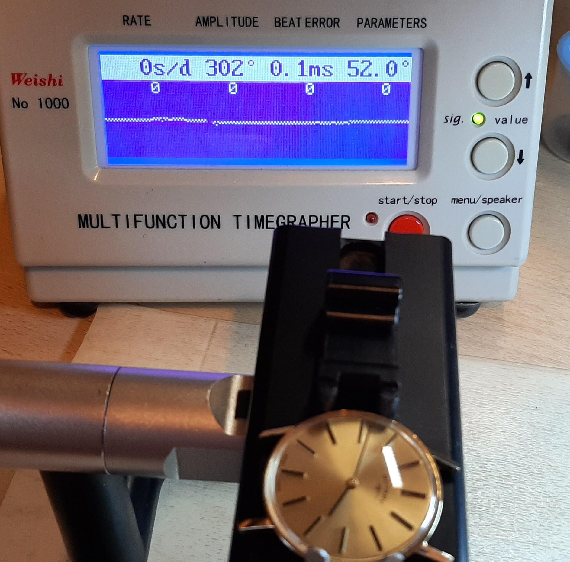
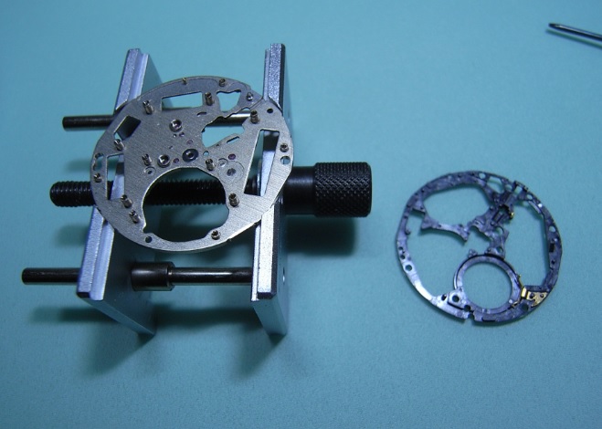
Just arrived, a Longines 30L. I've been looking for one of these for a long time. I've been a fan of Longines since I got my first, I love the quality and elegance. In the thread "looking for a simple, ultra-precise hand-wound movement - suggestions?", @nickelsilver suggested the larger Longines (30mm movements). The higher grade version of this movement (30Z) were used as observatory chronometers. So I decided I needed one. I'm expecting good performance. It's not going to just sit in one of my cases, I'm going to regularly use it. I bought it as "spares or repair", so was expecting a damaged balance. But on first look, the balance and hairspring seem perfect. It just seems to have a broken mainspring. Result BTW @nickelsilver, you also recommended Peseux as good movements. I bought a cheap Rotary with a Peseux 7050. Looked like it had been serviced by a gorrilla - the pallet fork was bent about 30°, missing pallet jewel, hairspring all out of shape. So I wasn't expecting great performance. On the timegrapher yesterday, looking good ! (I'll be buying more Peseux - good quality at a good price )
.thumb.jpg.ca502b3e67e1e13936648168231d15c1.jpg)
.thumb.jpg.b2036d29fafacc5dd87762d69c98ea08.jpg)
 5 points
 -
unless your super super stingy with your oil after runs for a while you should have oil on the locking face it will just transfer there all by itself3 points
-
Nice tool. Paper clip sharpened to a point has worked very well thanks on a few occasions.2 points
-
Oiling the faces of the pallet jewels provides a nice defined area to place the oil. The teeth pick up the oil, and have to distribute it to the locking surface. Keep in mind how little contact there is with the locking surface- you won't notice much oil there even properly lubricated. But if you place oil there, it will 99.99999% sure creep on up to the fork body.2 points
-
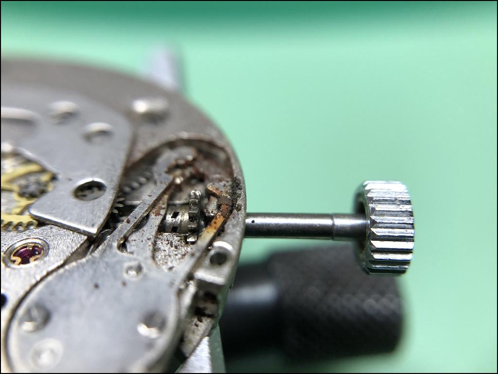
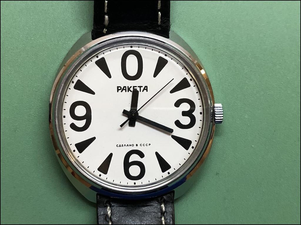
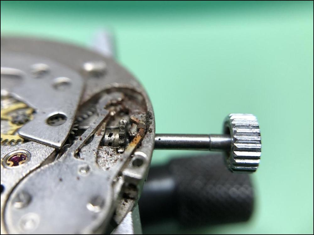
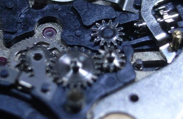
Long story short, when the Soviet Union collapsed so did the Russian watch factories including Raketa. Instead of money, the workers were given what was left of watch parts in the factory warehouse. To get ahead, the workers assembled watches independently and often used new cases, dials, and hands but used old and very worn movements. These watches were then sold on the street and eventually on eBay. There are still plenty of such watches on eBay. For example, this Raketa was sold on eBay as NOS and is a good example of one of those watches that were assembled after the fall of the Soviet Union. On the outside, it looks factory new. However, once you get to the inside of the watch this is often what it will look like and the only way ahead is, as John points out, to service and repair it, which often means that you'll also have to source parts from donor movements. Fortunately, donor movements can be found for very little money. So, I would expect that what I have described is exactly the situation you're in.
 2 points
 -
I assume this means that you're not the watchmaker? One of the problems when purchasing new item this if the new old stock and then not running that's not a good sign of well for instance did it ever run? Often times new old stock watches are new old stock because they had some issue of running in the first place. So basically somebody will have taken apart and look at it and see if they see any problems and if it is as simple as the lubrication is all gone bad unfortunately the old lubrication has to be removed and it becomes a complete servicing of the watch. In other words somebody has to entirely disassemble properly clean it and then relubricated as they reassemble it.2 points
-
I borrowed one from a Smith clock - 60 gms seems about right1 point
-
Thanks Richard, I tried to respond sooner but it didn't seem to work - all OK now though1 point
-
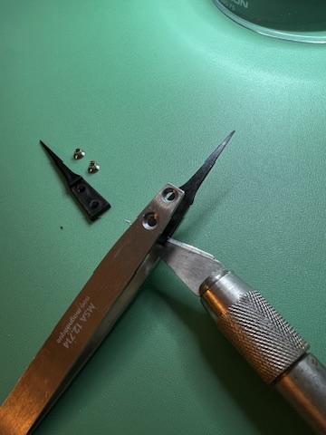
Update: Removal of tips. Once i figured out where to pry and what tool to use, the tip came off easily. Update coming: Installation of tips.
 1 point
 -
Hi all, My name is Elliott. I recently became interested in wrist watch repair/restoration over the last year. I have been working on vintage movements from ebay and really enjoy the challenge of it. Looking forward to meeting you all and learning from you. Thanks! Best, Elliott1 point
-
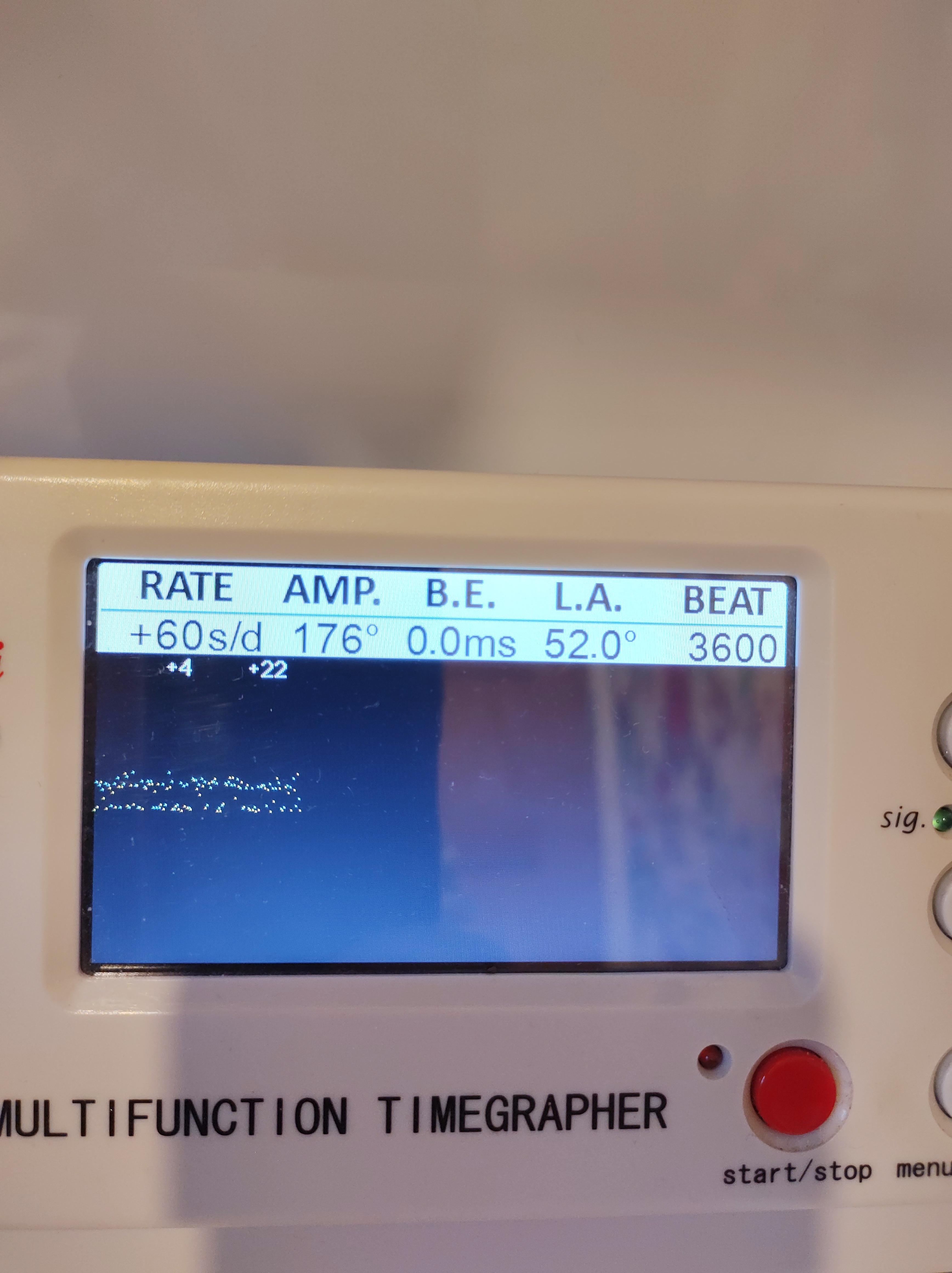
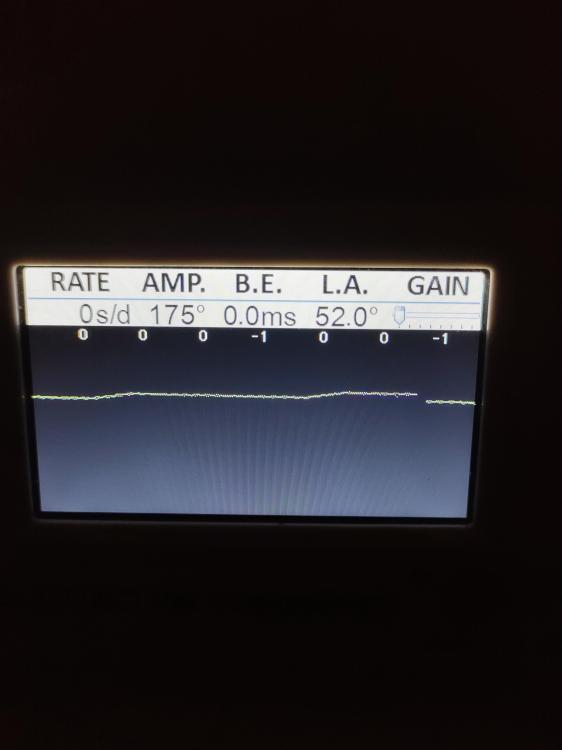
Getting close now, -0.04 SPD off wrist and doing an on wrist check now to determine which trimmer or trimmers should be moved to correct. I worked out how to get the clean trace on the timegrapher. I noticed that the trace cleared up between 10:30 and 12 midnight. It clears up when the train of wheels is being loaded by the date wheel changing over.
 1 point
 -
I am inclined to agree with you, with emphasis on "initially". Again, I'm inclined to agree. Perhaps that would be a more efficient way to get the watch to perform its best in a shorter period. Perhaps you have just improved the age-old way of lubricating pallets?! Anyway, the locking distance (1/3 to 1/6 of the impulse face) is so short that I think it would be nearly impossible not to make a mess of it.1 point
-
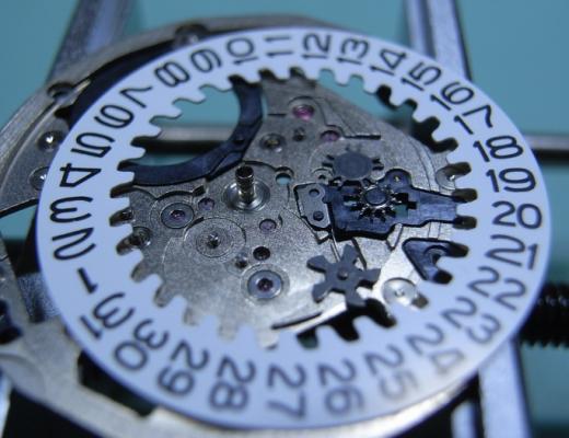
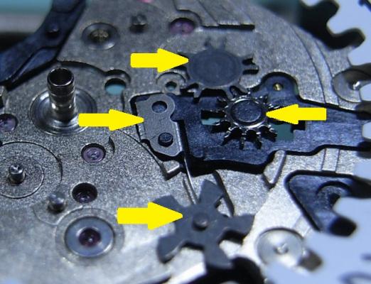
Are you sure the snail (hour wheel) is in the right place, have you tried moving it by one tooth.1 point
-
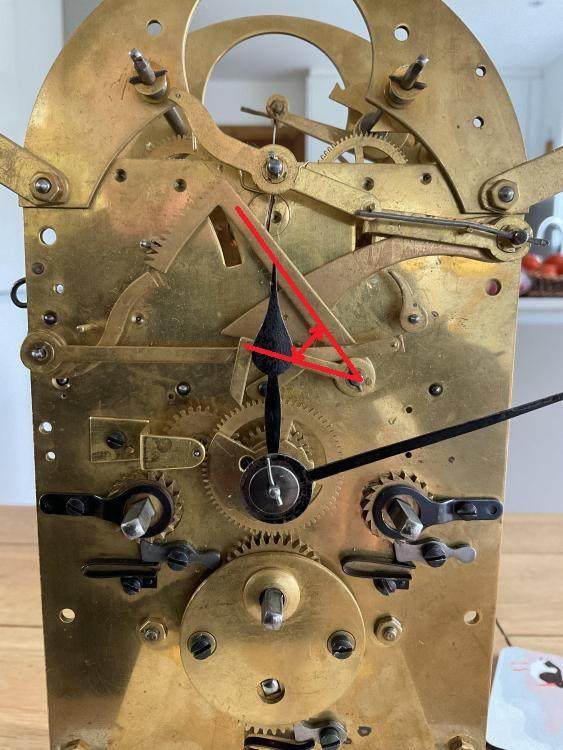
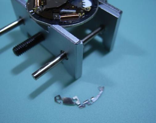
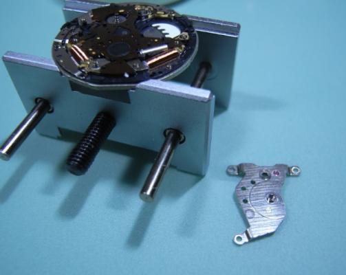
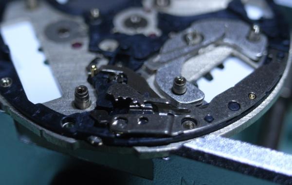
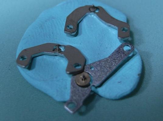
In case You still didn't find the answer... I am not sure about the english names of the parts. The angle between the two parts of the lever shown on the picture has to be enlarged (opened) a little. In the state of preperation, when the downside part has fallen on the snail, the correspondent tooth tip must point straight against the pivot, on which the pin that moves the lever up is placed. Be sure that the hour wheel is placed correctly so the downside part of the lever falls in the middle of the steps of the snail. You can see that someone drilled hole and put rivet there, but He didn't do His best to align the parts or with the time alignment changed.
 1 point
 -
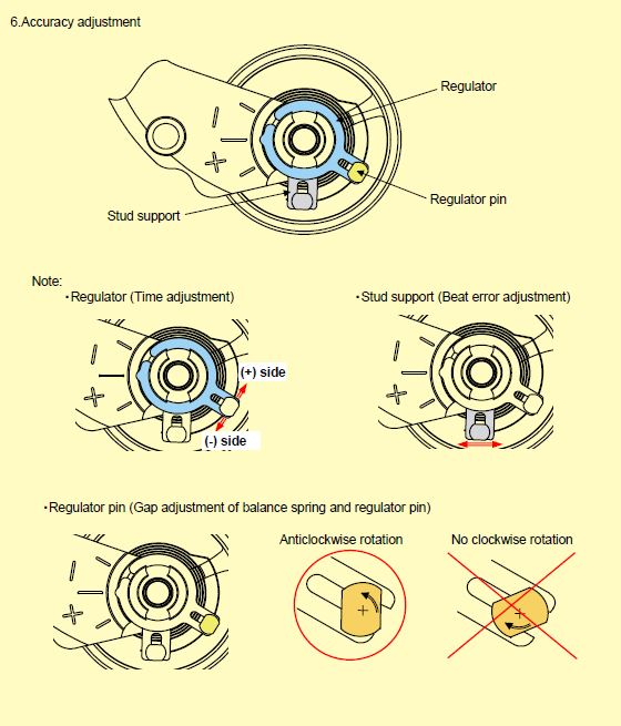
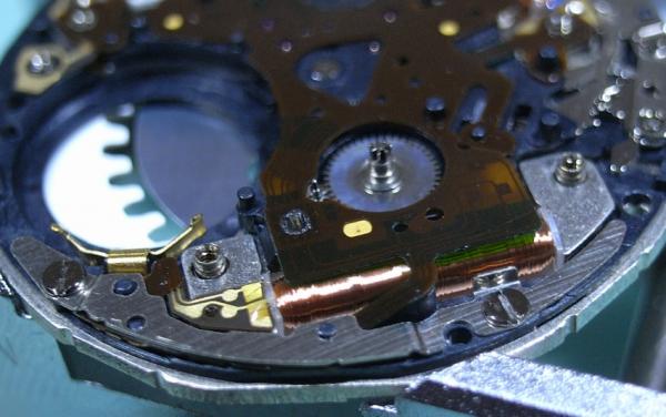
I think mangled is a bit of a harsh word here. let's interesting in the world of horology the battle of Japanese watch manufacturing with the Swiss is that sometimes they share things like the system here of the regulation on the stud commonly called a Etachron system the Swiss hold the patent for one part and the Japanese hold the patents for the other part. I'm attaching an image so you have a better idea of how things look. For now what I would do is just open the regulator up to its maximum and just move it out of the way see you can see if they hairspring got bent there. you and up with way more adjustments which of course will cause way more confusion when you're trying to figure out what you're trying to do here.
 1 point
 -
My thoughts are to do with the draw of the lock. Generally we oil the impulse face of the pallet jewel , thats what everyone tells us to do. But what about the locking face of that jewel, that has to draw up to the root of the escape tooth. Looking at the action there might be more friction created from the pressure coming from the escape wheel that is pushing in the opposite direction to which the jewel wants to push the escape wheel during the slide up of the draw, thats where a lot of the energy robbing of the escapement is .I understand the geometry of the pallet is designed in such a way to make it slide. So does oiling the impulse face transfer oil to the locking face ? I dont think so, not initially. So does oiling the locking face transfer oil to the impulse face ? I think it does , at the corner of those 2 faces. Thoughts people please.1 point
-
Yes, reshaping of the end curve is definitelly needed. This can be done without taking out hte stud from the holder at all. The spring is not clamped in the stud, it is glued with heat melting glue and it is not protrding from the other side like in old watches that have 'reserve'. So it is as it should be there.1 point
-
Well, actually the Russian springs with T briddle are same as the swiss ones. The way is to wind the spring in the winder barrel not to the end, but 2-3 cm of the end to protrude from the barrel. Then put the winder barrel in the watch barrel and rotate the winder to get the T end coincide with the notch, then drive the 'ear' of the T end in the barrel notch and hold i with something pressed there, push the spring out of the winder and that's it. In case of SLAVA alarm clock spring - yes, it is to big for normal winder1 point
-
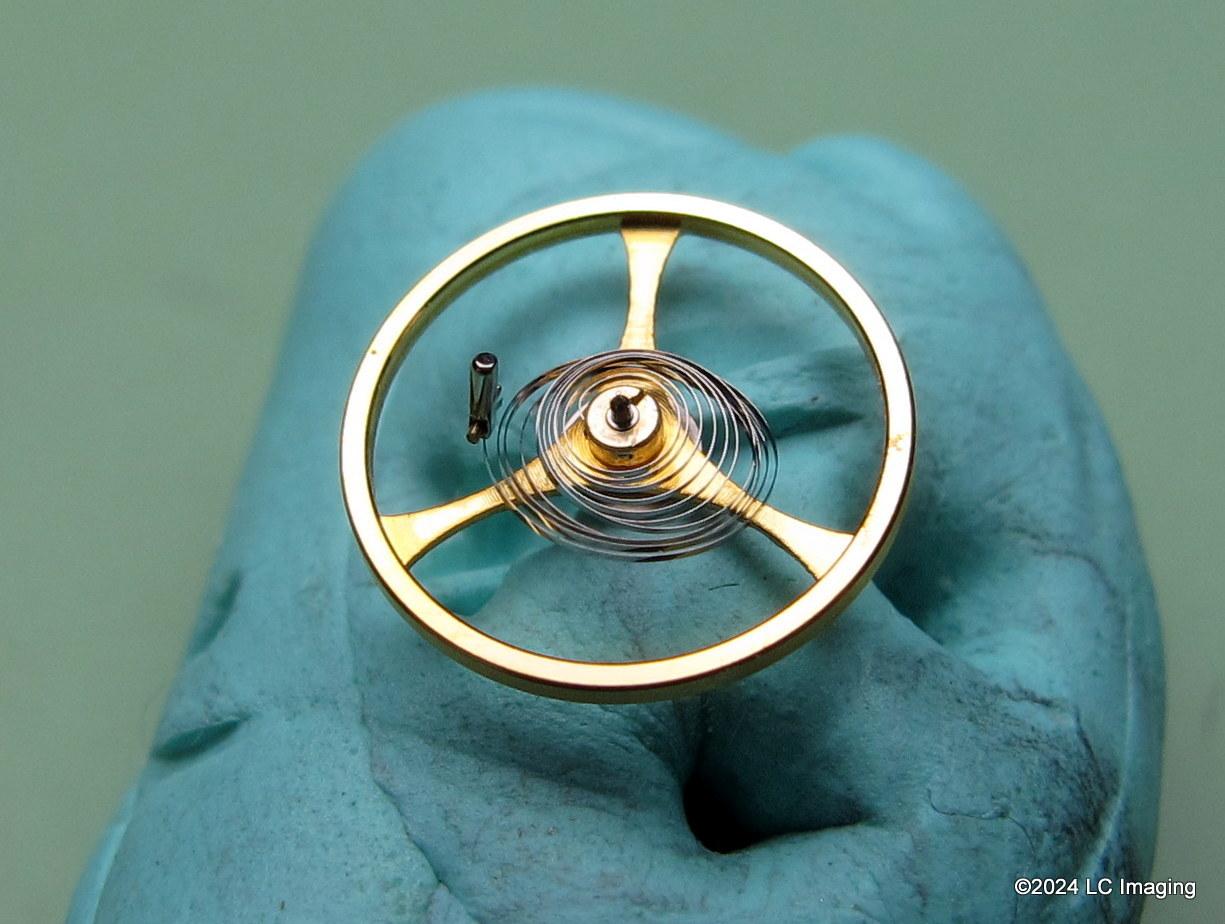
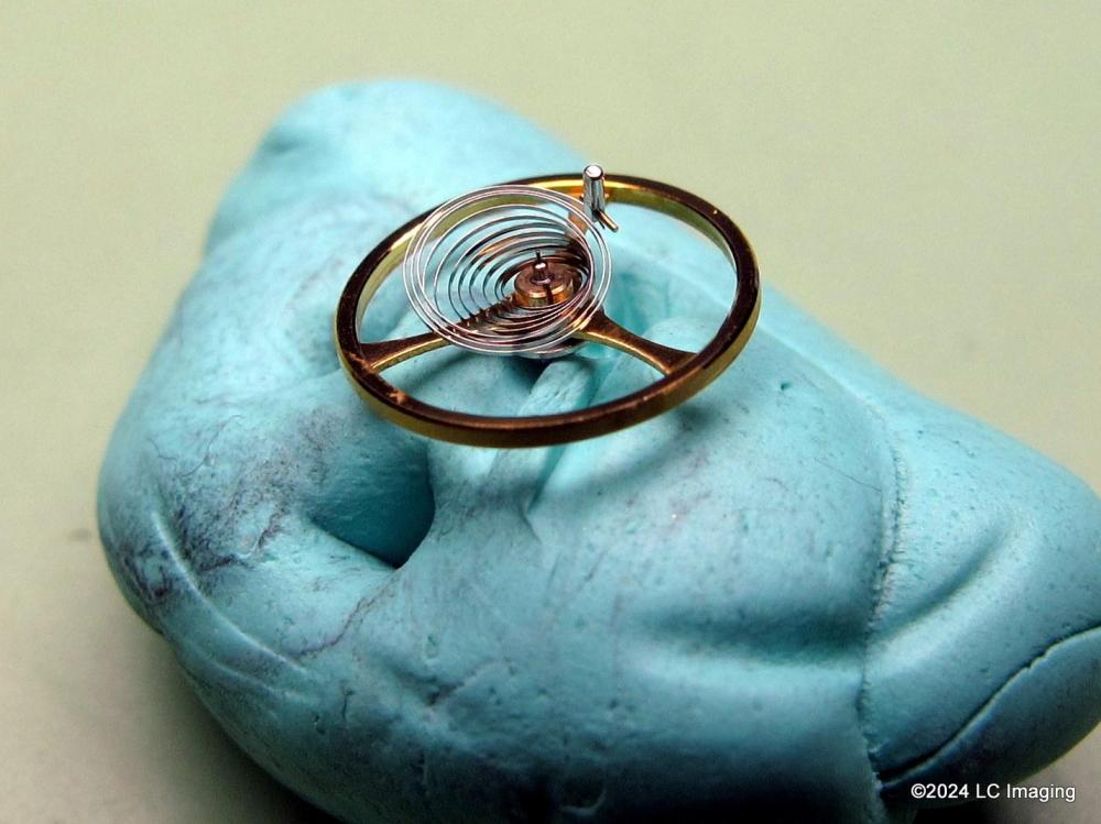
Hi lex, some centering of those coils needs to take place. First make sure that the hairspring is thoughly clean and nothing sticky remains, magnetism shouldn't be an issue as modern ( last 70 years bright nickle alloys ) hairsprings are non magnetic. Next check its freedom between the regulator pins, which at the moment doesn't look like it is, seems to be nipped, notice the gap between the end curve and the.1st coil is wider on both sides of the regulator. Once free turn the stud for some concentric adjument of the coils, if that looks ok then the regulator pins can be closed up and checked for hairspring freedom all along the terminal curve. Maybe some reshaping of it like Hector suggests as the curve looks a bit raggy.1 point
-
Elgin 206 is a hunting movement, this one happens to have a conversion dial with no seconds hand that makes open face, stem at 12. This is a few weeks old. Last week I did find someone selling a random assortment of 16s and smaller sleeves inexpensively. I needed approx 4.2mm thread and 7mm overall length. My assortment had one that fit and I was able to move forward.1 point
-
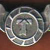
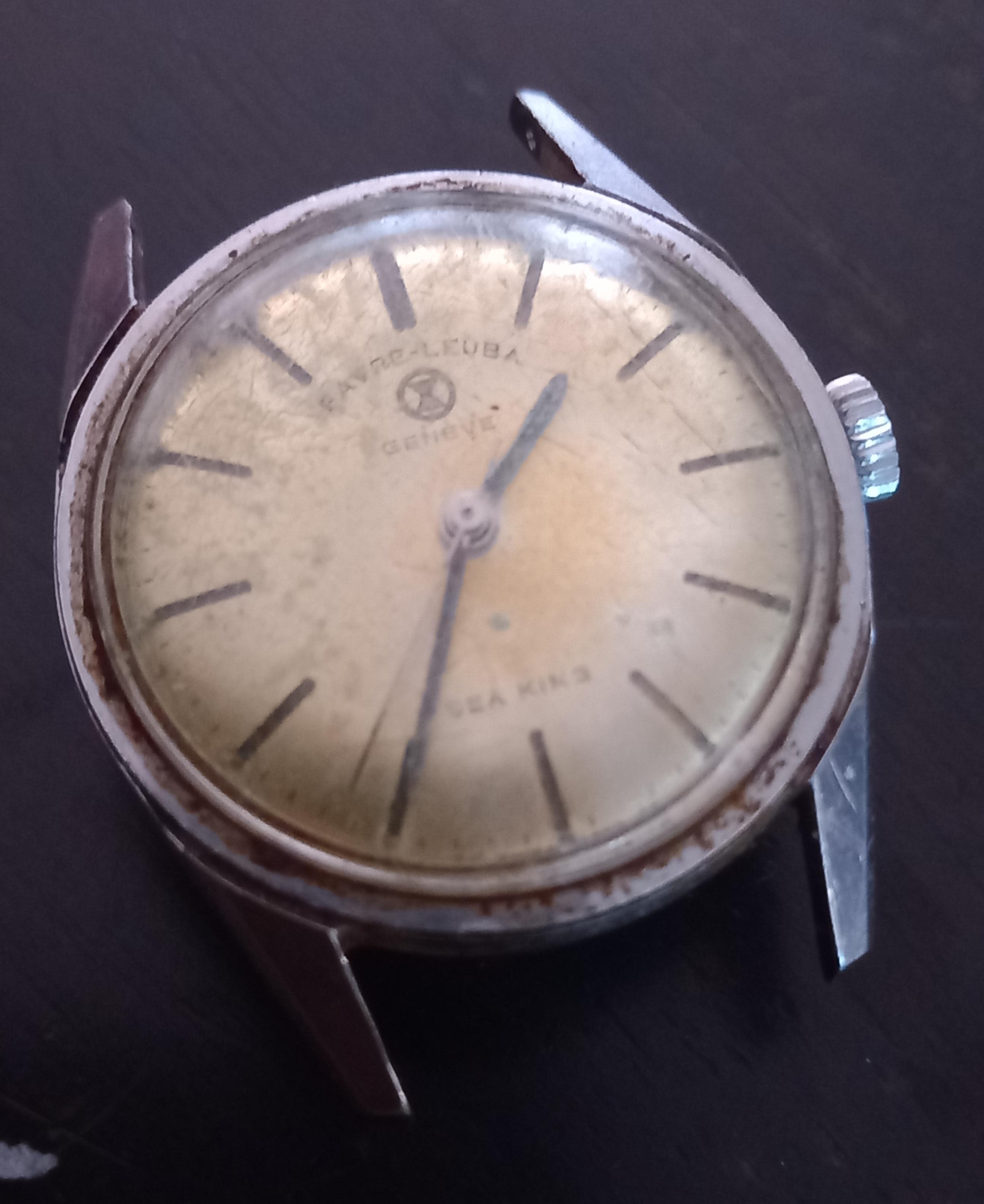
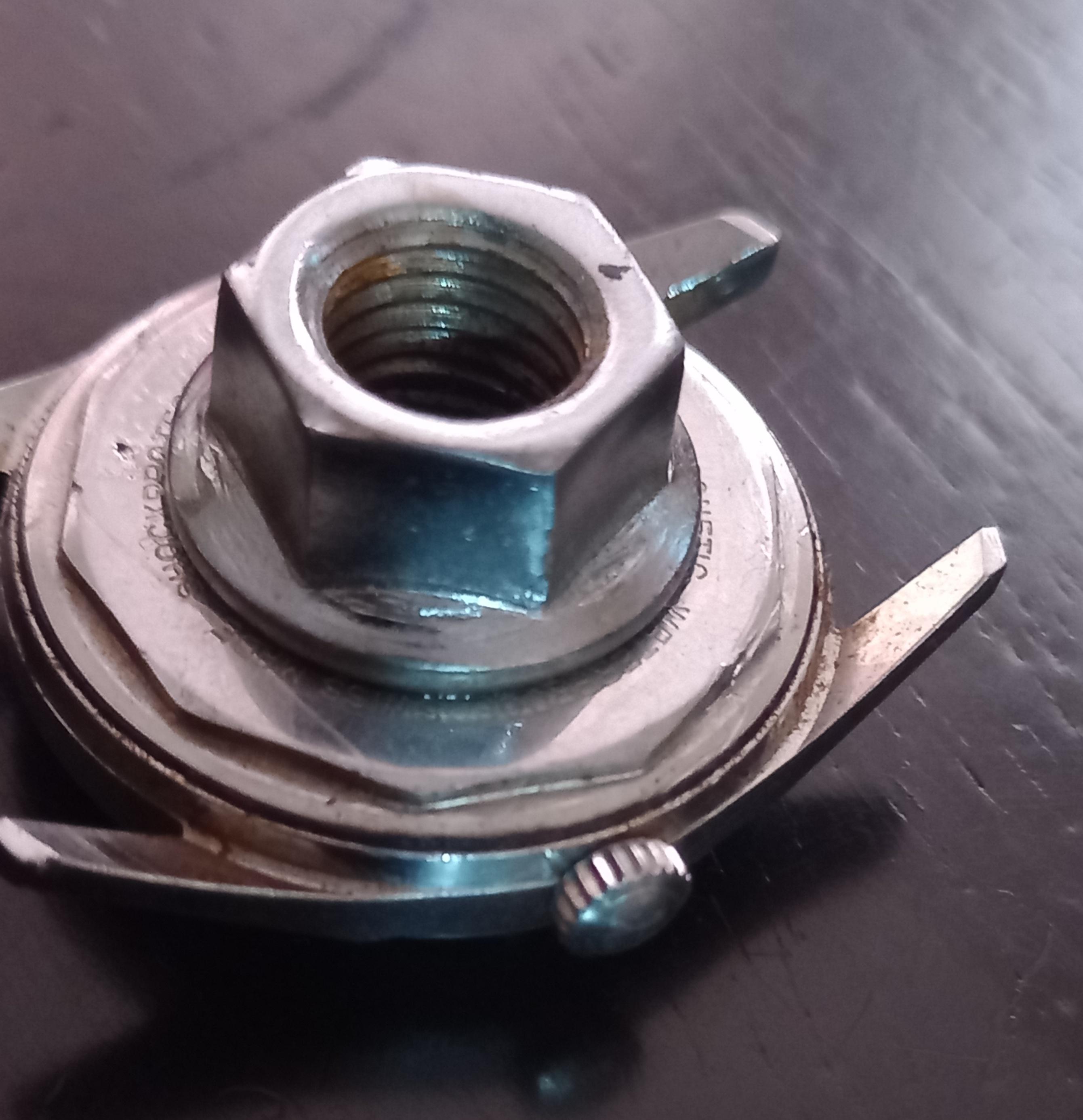
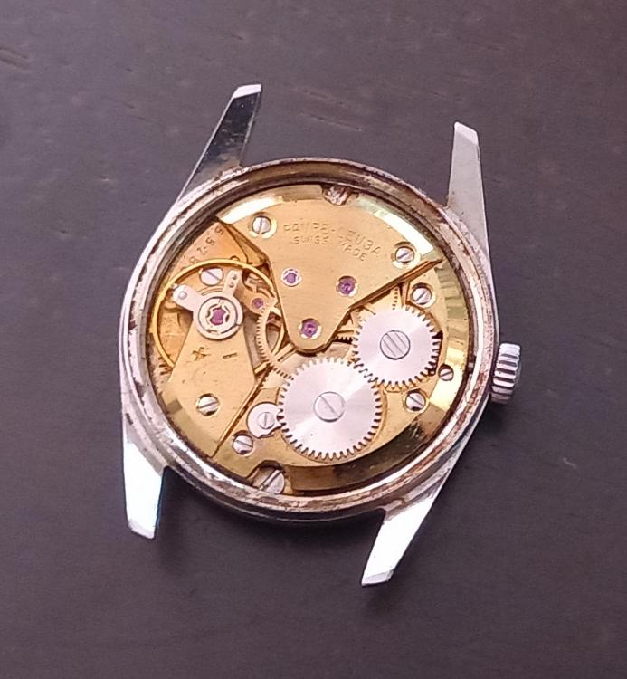
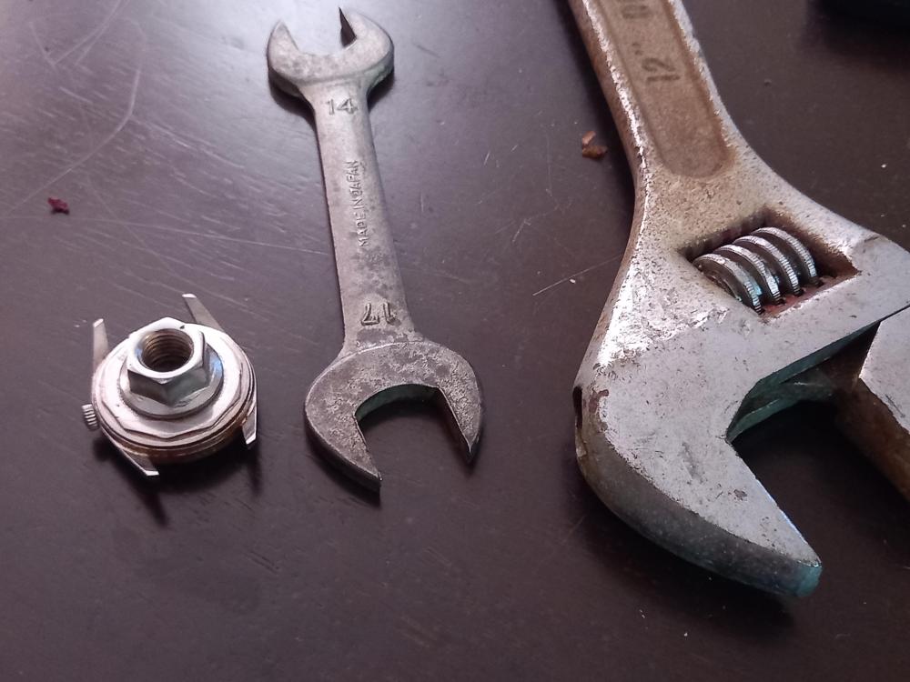
Hi all, Just got an old Favre Leuba and the caseback was well and truly stuck. Usually in this situation I would bring it to my mates shop and use his bench opener but as this Favre-Leuba has flats they usually don't work as well. Anyway, another solution is to glue a nut on the caseback and use a wrench on that. Well the superglue is pretty much a necessity for me and there are usually a few tubes in the freezer ...result! After 10minutes for the glue to set, a big adjustable wrench between the lugs and a 14mm spanner in the nut/caseback and it spun right off!. I must say the caseback did a good job keeping the movement clean! This trick has helped me out a few times. If you plan to do this just make sure you keep the superglue away from the caseback/case joint. If any superglue wicks into the joint then things get difficult! Anilv


 1 point
 -
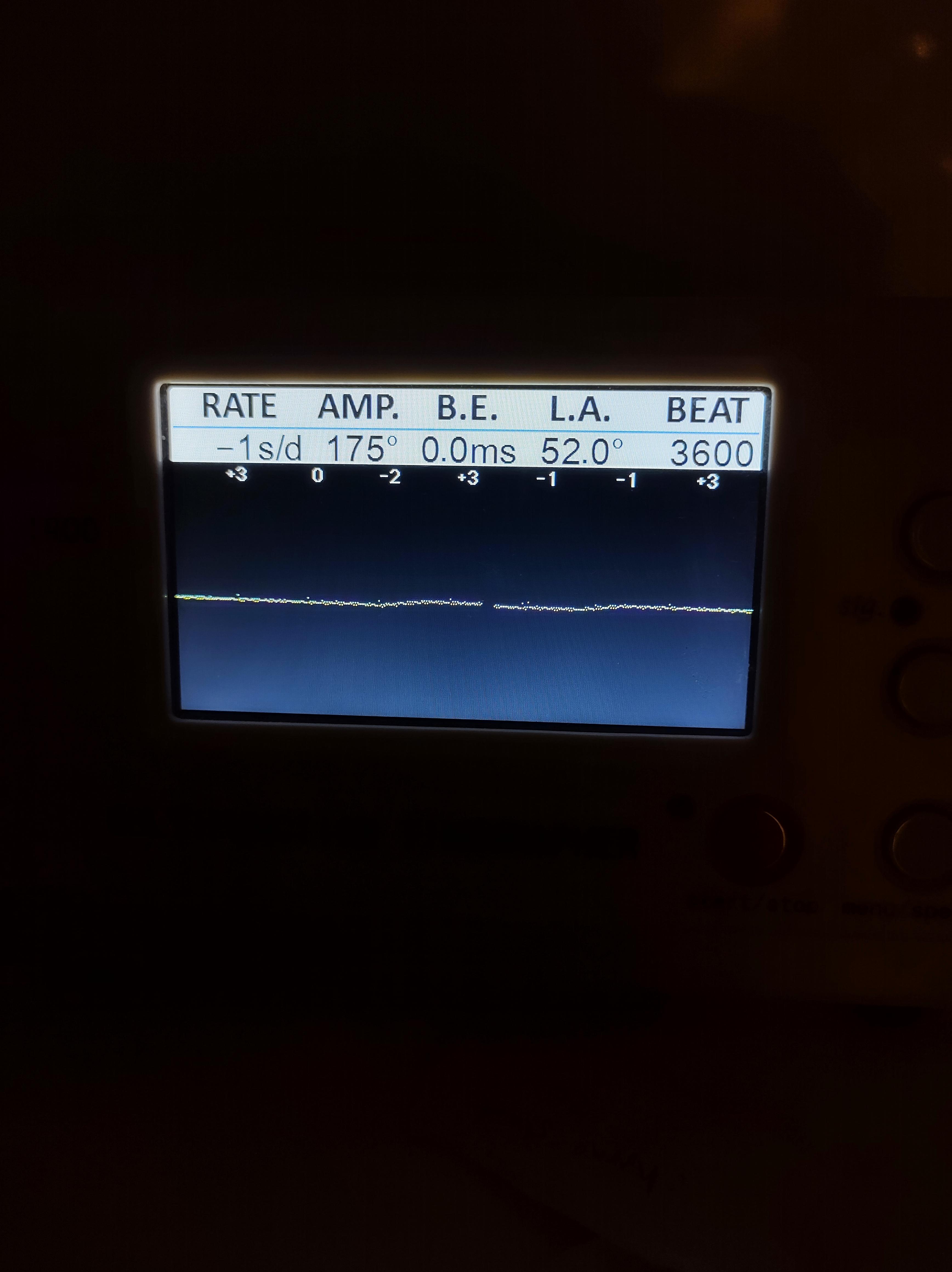
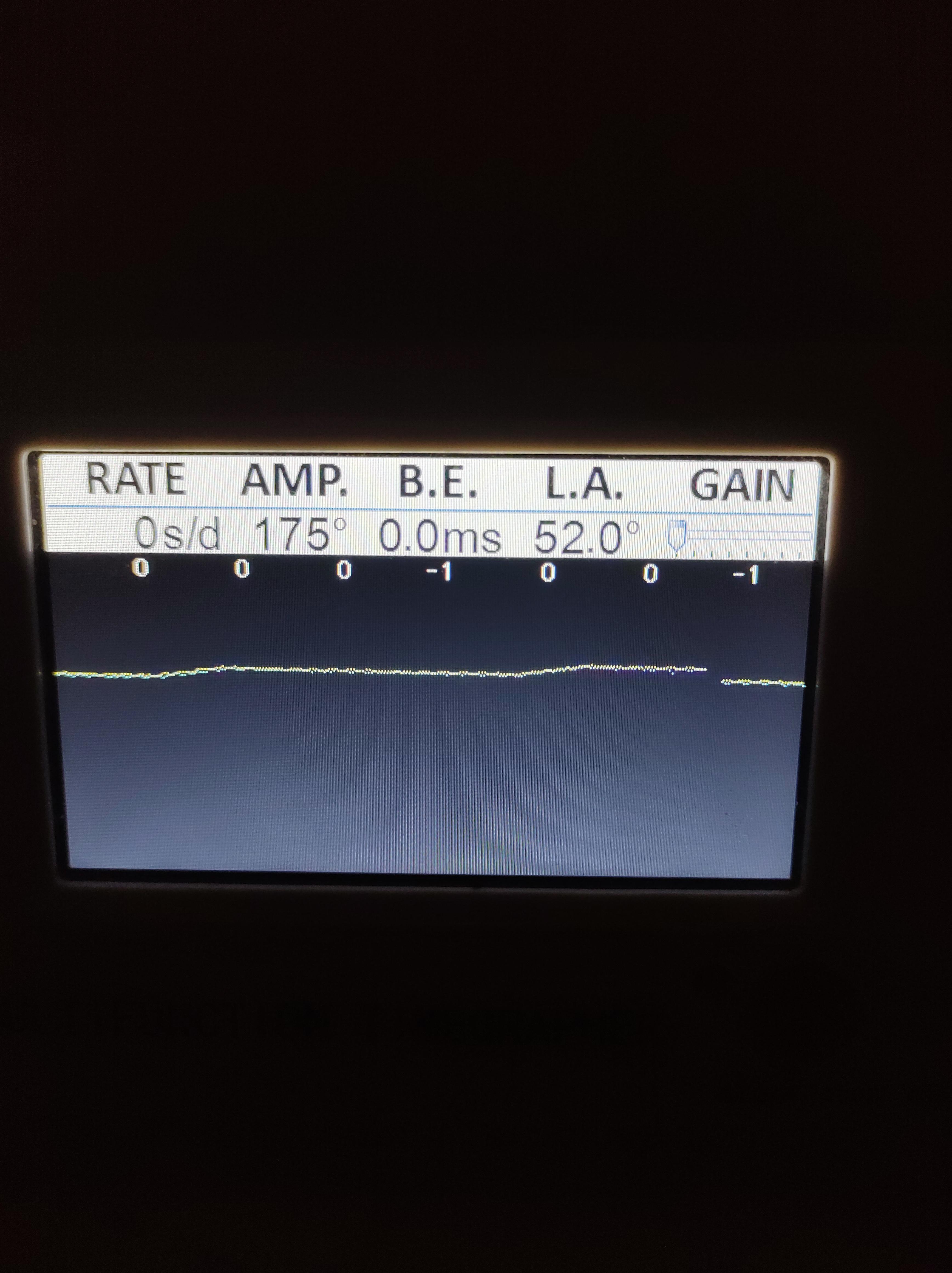
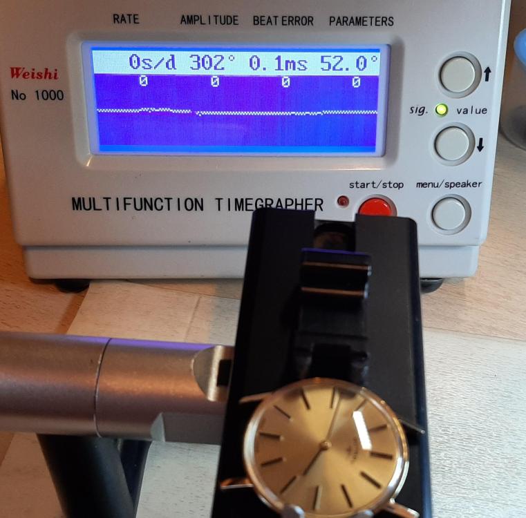
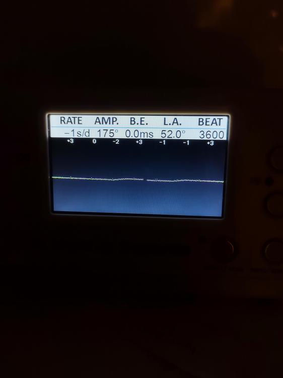
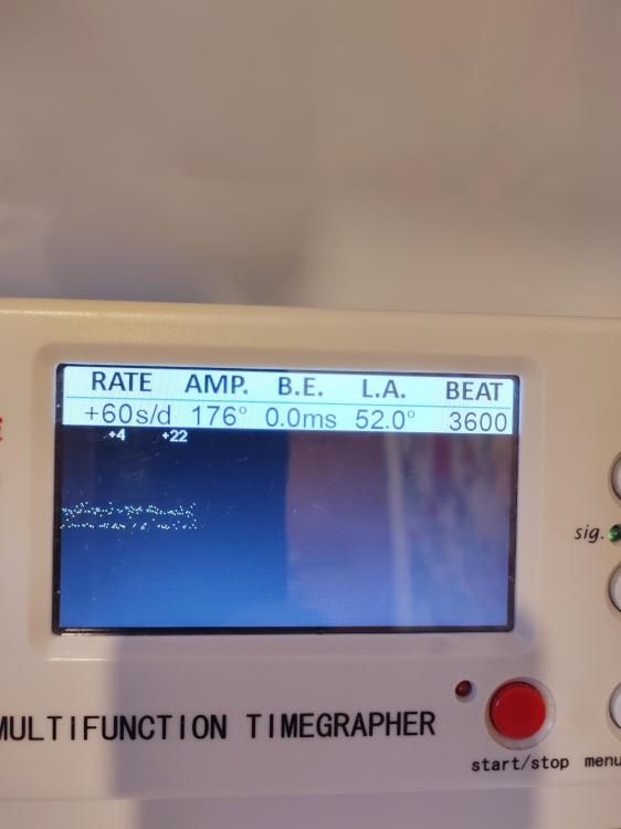
I just wanted to share an update . I'm getting quite close with the regulation. Latest is +0.1 SPD off wrist (16 degrees) and +0.04 SPD on wrist. Some observations: A timegrapher set on 3600 bph is a very useful tool even for quartz to get you in the right ballpark before you attempt the fine regulation. Normally you will see a noisy band across the screen but you can tell if that is sloping up or down, an indication of rate. A hairdryer can be used to increase or lower temperature quickly. It can be used while observing the rate on the timegrapher. If the temperature compensation is a long way out then you can see huge swings in rate as the temperature changes, as an example, from 0 SPD on wrist to +3 SPD off wrist. Occasionally the timegrapher noise clears up (no idea why) and you can see how the compensation is working. See image attached (16 degrees) that shows a slightly negative rate that is compensated every minute or so with a small period where the watch runs faster. I have tried to mathematically model (using a graphing equation website called Desmos and a simple model based on x squared curves) how the rate will react with small adjustments to the two trimmers. I think this will prove useful and it has shown that small tweaks of both trimmers alternately should be needed to achieve the flat response. Basically the model is showing that adjusting the main oscillator will cause an unintended slope in the temperature response. An adjustment to the temperature response should then required to correct and flatten the slope. Wish me luck Also one more observation. When you are getting close then the adjustments required are very small. Without a stereo microscope this way of adjusting would not be possible. The adjustments I am making each time are moving the trimmer by approx just one quarter of the width of its screw slot, possibly even less.
 1 point
 -
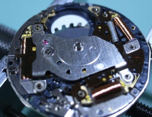
The V-L scale and the square that can be turned is for adjustment of repeater speed. On the bottom of the square part is the hole of the last bearing of the repeater train, where only small pinion with no table sits. Turning of the square changes the distance between this pinion and the wheel that iti is meshed to. !!! decreasing the distance is possible beyond the point where the pointer leaves the scale and forcing in this direction will lead to breaking the pivots of the small pinion!!! What I wanted to see is the teeth of the crown wheel. The crown wheel is seen, but it teeth are under the down side balance kock, so please make picture from another angle, that alows to see the teeth. Actually, the teeth are seen on the next picture and seem to be good. The chain is placed on it's place AFTER assembling of the movement. It is easier to do it when the movement is assembled, but balance is not in it's place, so the train can move freely. Then, the barrel end (hook) of the chain is attached to the hole on te barrel. The barrel is rotated by wooden stick untill the chain is fully wound on the barrel. Then, the fusee end is atached to the fusee, some force is aplyed to the barrel in order to strain the chain and to let the train move untill the fusee gets to the position where the chain is strained and no more turning of the fusee is possible. Then, holding the barrel not to let the chain get loose, the ratchet wheel is put on the square of the barrel arbor, the arbor is rotated in a manner that the spring is wound a little and will hold the cain strained, and the click is engaged with the ratchet wheel. Then, block the train and wind the spring slowly (by the fusee arbor) and the same time observe if the chain goes correctly on the fusee channel. If needed, help the chain not to go out the channel, this is only when first winding. After that, release the train and let the spring unwind by train turning. !!!All train bearings must be oiled!!!1 point
-
Full plates can be difficult, there is a lot to accurately position under the plate in one go. Try putting one or two plate screws in at one side but only lightly screwed down and then carefully feeding each wheel into its respective hole from one side of the movement to the opposite end .Gradually turn the screws down very carefully as each wheel falls into place. This way each progressively placed wheel stays in position.1 point
-
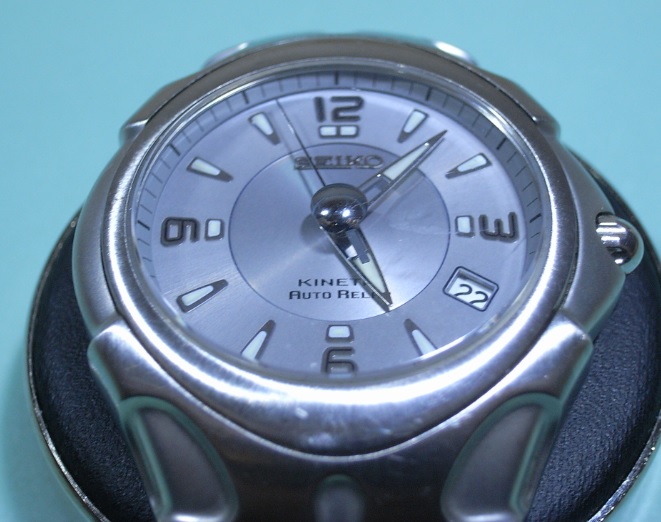
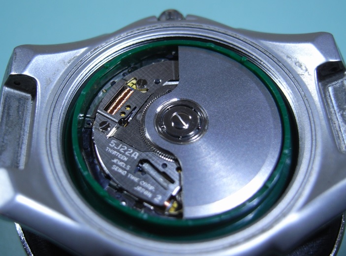
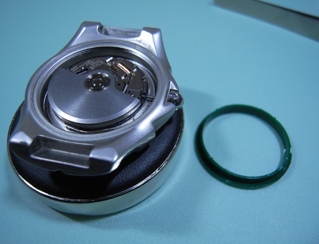
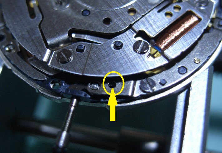
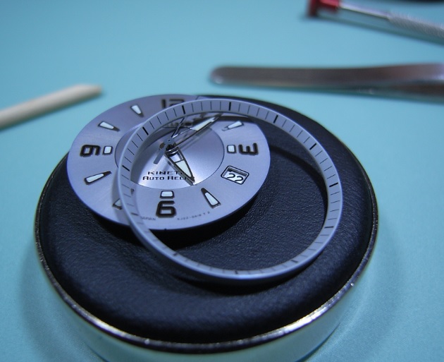
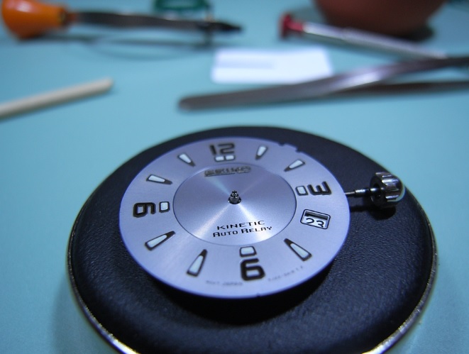
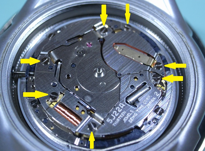
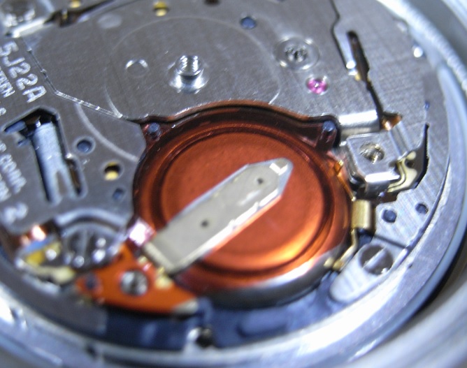
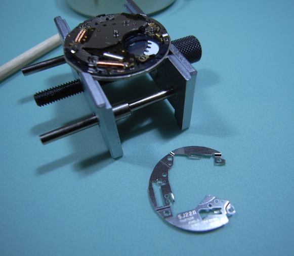
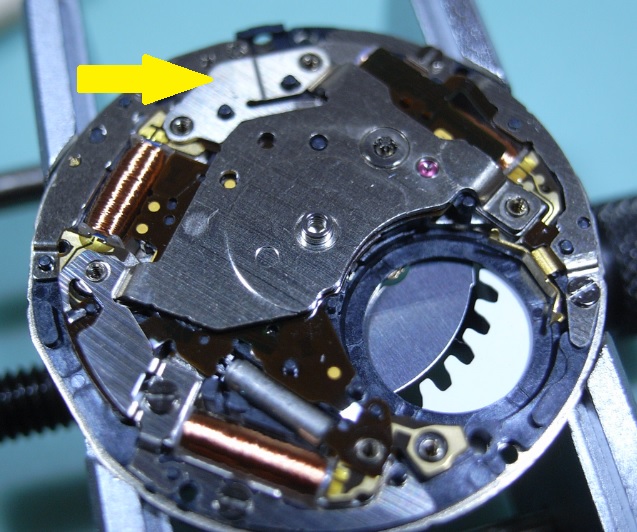
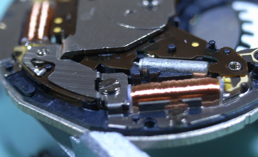
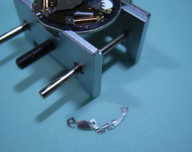
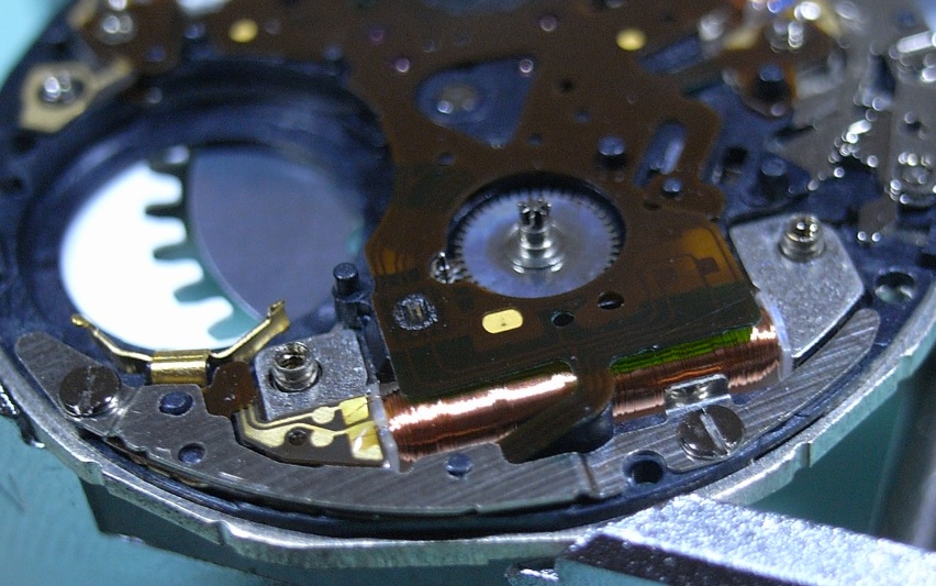
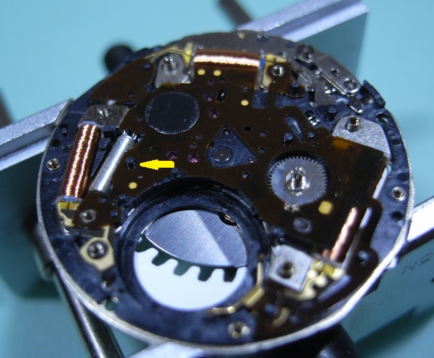
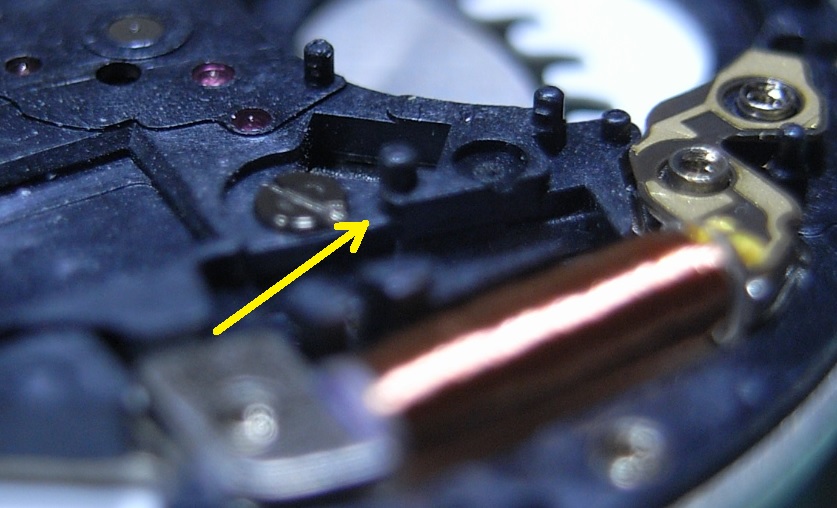
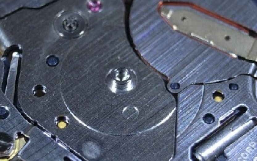
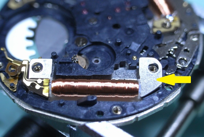
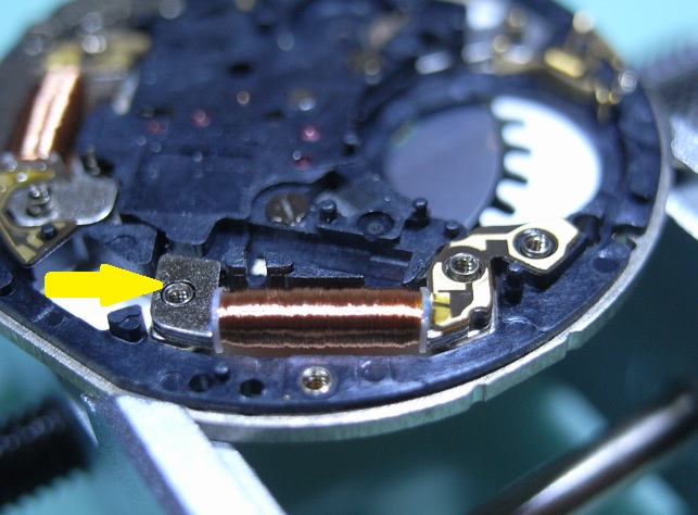
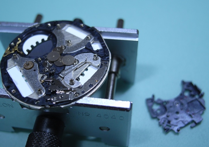
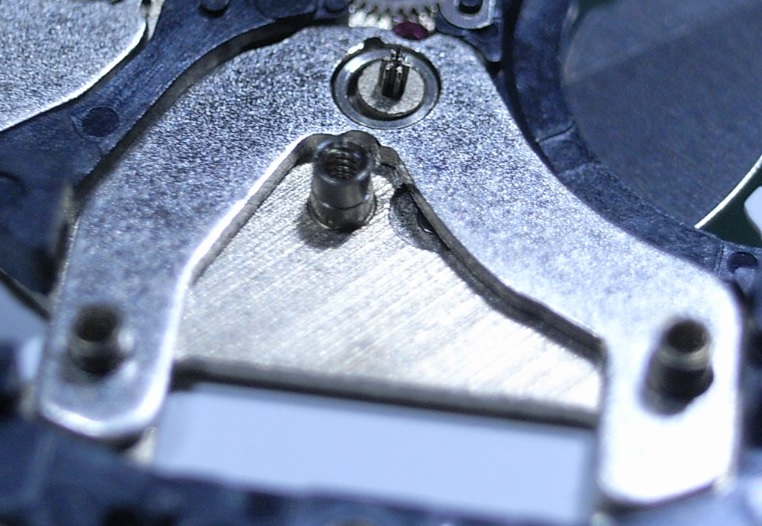
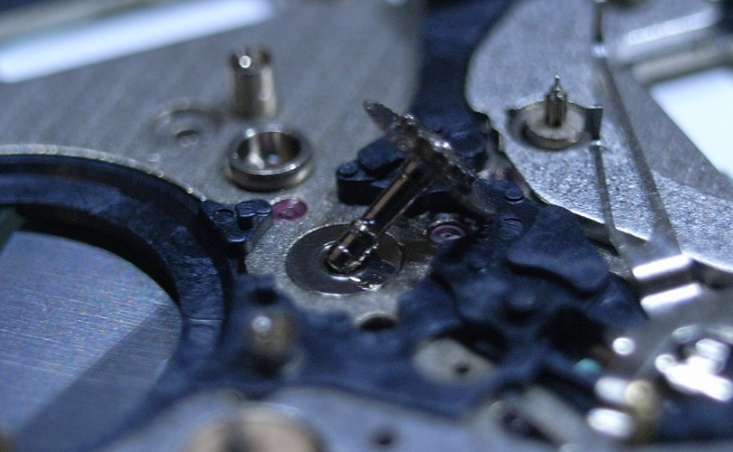
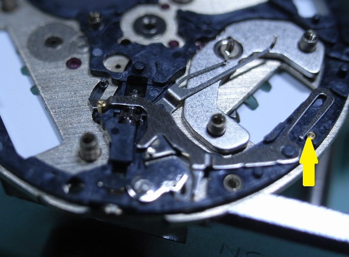
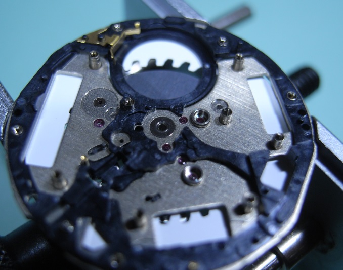
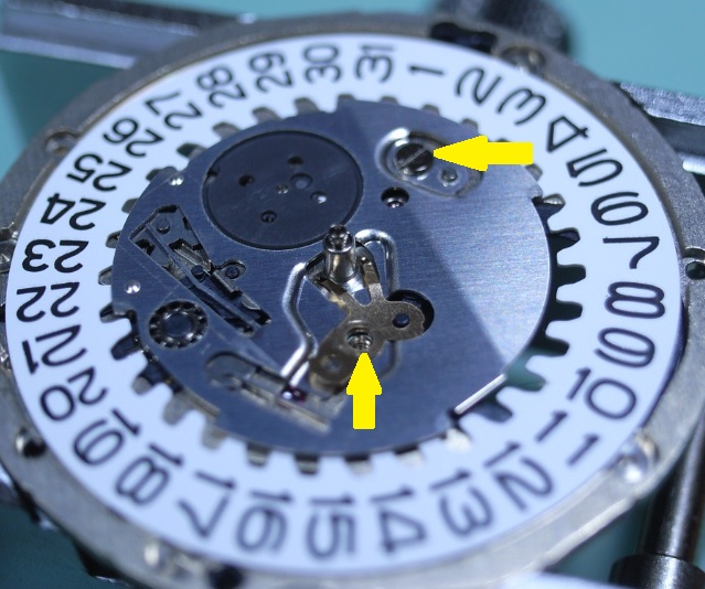
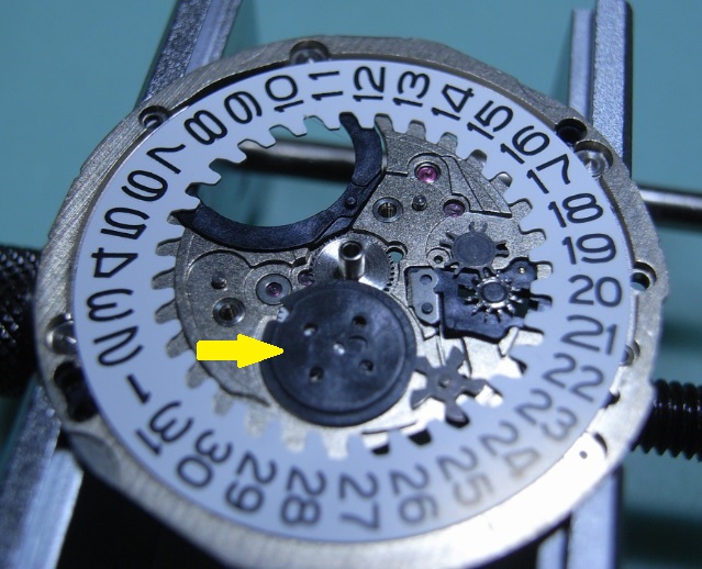
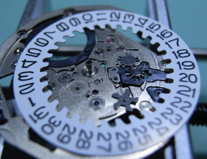
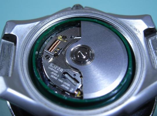
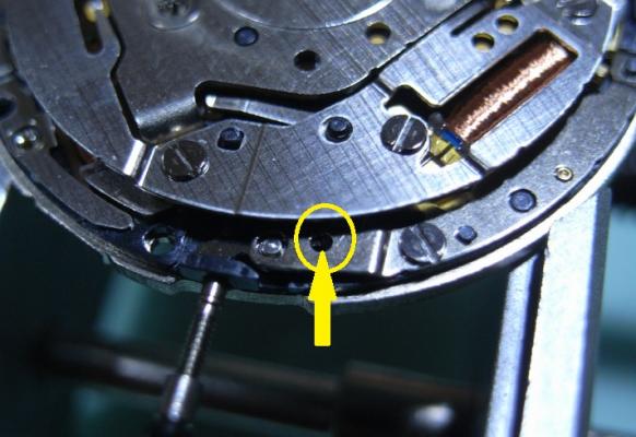
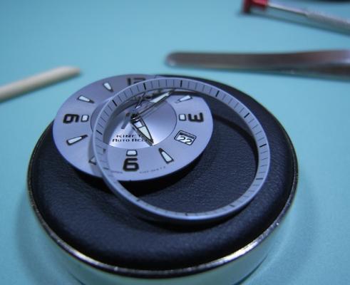
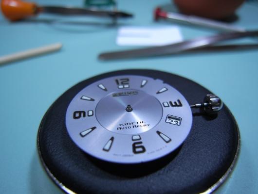
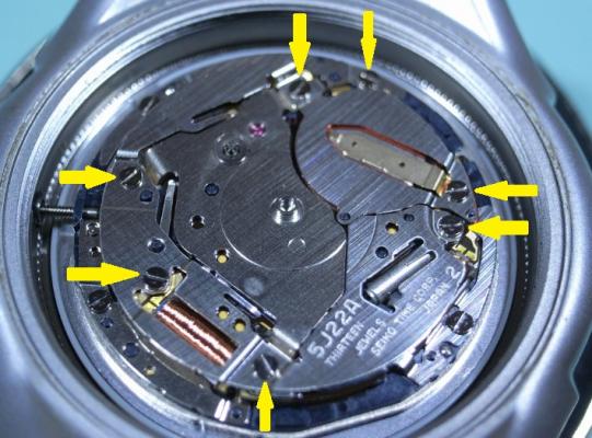
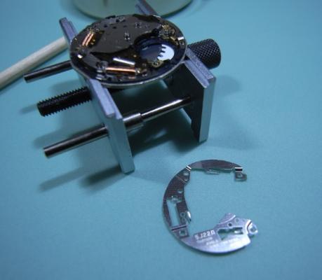
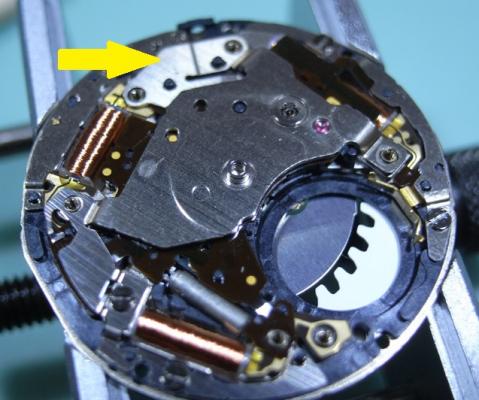
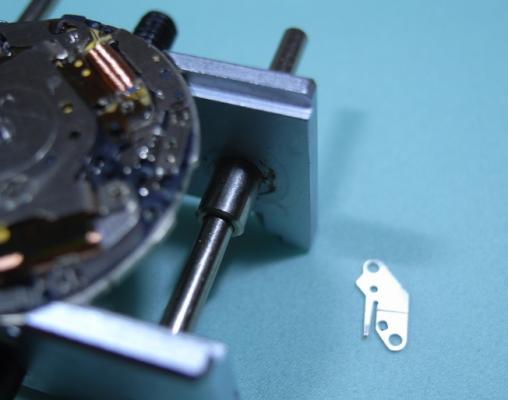
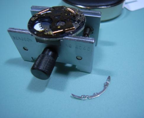
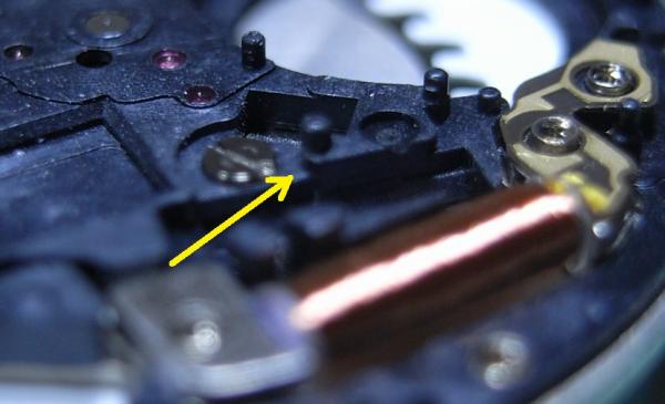
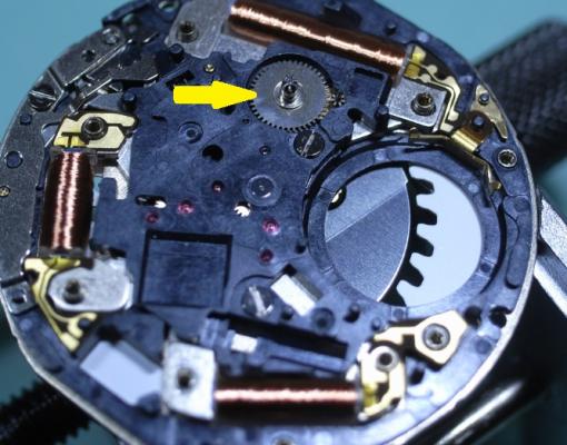
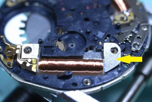
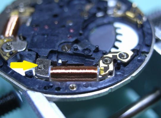
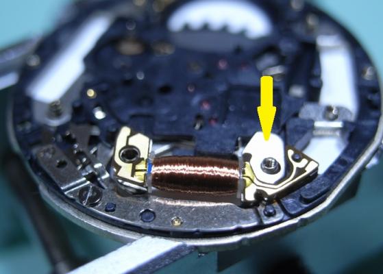
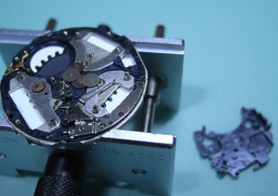
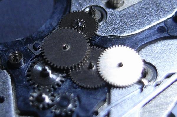
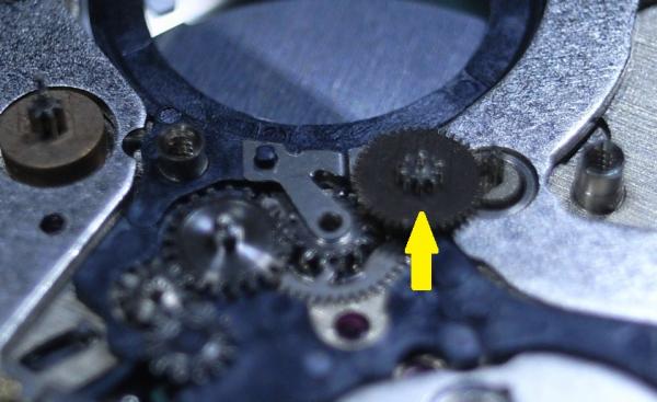
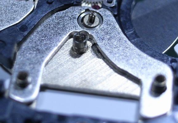
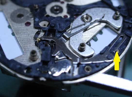
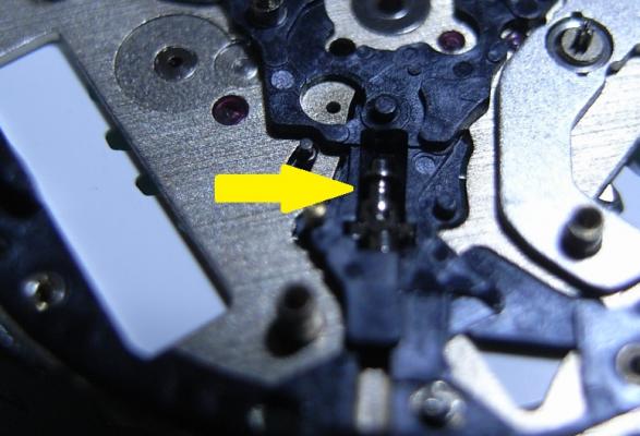
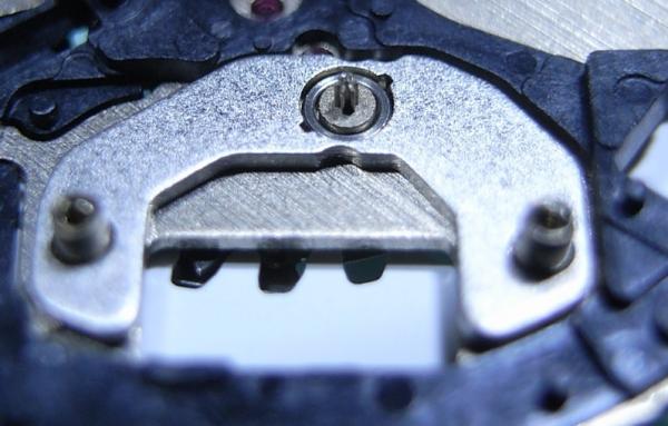
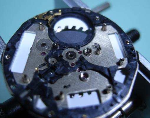
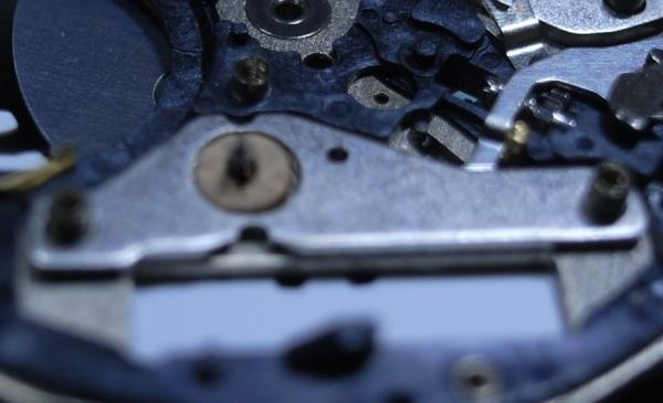
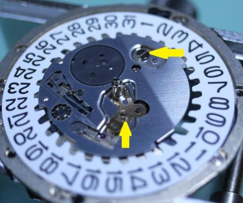
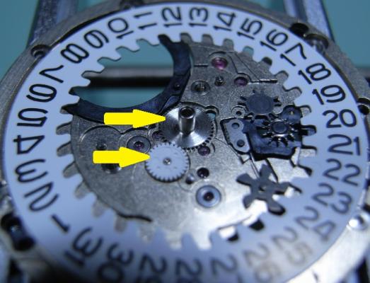
Seiko 5J22A Complete Service Hunting through my cupboards I found my old Seiko Kentic "Auto Relay" that I purchased sometime in the 90s, when this was the latest cutting edge Quartz Watch on the market offered by Seiko. It's been sitting for over a decade without use, and I decided to really push myself and, with the Lord's assistance, completely strip and service this watch. So I tracked down the Tech Specs, and if you are thinking of embarking on servicing the 5J22 YOU WILL NEED THEM!! :) So here they are: 5J22A.pdf I will be using the part names from this document for this walkthrough, so download and print it out for you own sanity. The parts in this movement are incredibly small, so much so that my camera had trouble focusing on them ... so part names will help you as much as the visuals aids for this service. Once again, I've had no one to guide me on this, so this is the way "I" stripped the movement down, the correct factory procedure may, and probably does, differ from my way ... so I give a warning here: CONTINUE AT YOUR OWN RISK. Disassembly Unscrew the back cover and store the rubber gasket away safely. With a 2.0mm Screwdriver, pry the Location Ring out with the slots provided in the plastic ring. Remove the Oscillating Weight with a 1.20mm Screwdriver ... and this will be the driver you use on all further screws. To remove the Stem, you need to have the Stem push all the way home, to move the Yoke into the correct position so you can depress the lever (Location shown in picture after I removed the movement to make it easier to see the spot where you push) The movement should now come out of the case along with the internal Bezel Ring. Remove the Hands Remove the 7 screws for the Circuit Block Cover A, and the Rechargeable Battery Clamp (Sorry referred to an older pic to so you the location of screws) Remove the Insulator for Rechargeable Battery, and then the Battery itself. Remove Circuit Block Cover A Remove Circuit Block Cover D Reference picture of Circuit Block Cover D Remove Circuit Block Cover B Reference picture of Circuit Block Cover B Remove Oscillating Weight Bridge Reference picture of Oscillating Weight Bridge Remove Circuit Block Cover C Reference picture of Circuit Block Cover C Remove Circuit Block NOTE: The pin with the yellow arrow pointing to it holds onto the Circuit Block very firmly. Be CAREFULLY and GENTLE, as the Circuit Block can be easily damaged. This is the angle of attack that I recommend. Coming in on an angle just in front of the Crystal Unit, and gently push upwards ... and I mean GENTLY. Patience wins the day! Remove the Intermediate Wheel for the Generating Rotor Remove the Generating Coil Block (grasp with tweezers where indicated with yellow arrow) Remove the Second Coil Block (grasp with tweezers where indicated with yellow arrow) Remove the Hour and Minute Coil Block (grasp with tweezers where indicated with yellow arrow) Remove the Train Wheel Bridge Remove the Second Wheel and Pinion, the Third and Fourth Wheel Remove the Intermediate Second Wheel TIP: Next is this first of three sets of Stators and Rotors that make up this Quartz Movement. Be sure to place all the Stators and Rotors into a piece of Rodico for safe keeping. As shown below: THESE PARTS ARE MAGNETIC AND WILL ATTRACT PARTICLES, SO DO NOT PUT INTO THE BASKET FOR CLEANING Remove the Second Stator and Second Rotor Remove the Minute Wheel and Pinion, Intermediate Minute Wheel, and Setting Wheel Remove the Center Wheel and Pinion Remove the Generating Stator and Generating Rotor Remove the Setting Lever Spring Remove the Yoke and Setting Lever Note: Release tension on the Yoke Spring FIRST Remove the Clutch Wheel and the First Intermediate Wheel for Calendar Corrector Remove the Hour and Minute Stator and Hour and Minute Rotor This side of the Main Plate is now finished ... time to flip it over and start on the Calendar Works Remove the two screws indicated and remove the Hour Wheel Guard Spring, and the Date Dial Guard Remove the Intermediate Date Driving Wheel Remove the Intermediate Hour Wheel, and Hour Wheel Remove the Date Dial Remove the Day-Date Corrector Wheel, Second Intermediate Wheel for Calendar Corrector, Date Driving Wheel and Spring Note the position of tension of the Date Driving Wheel Spring (bottom of page 9 in the Tech Specs) Remove the Circuit Block Spacer ... and the disassembly is complete! I started work on this rather late at night and took my time and studied each part before removing, making sure to document everything carefully. So I'll clean the parts and begin reassembly fresh tomorrow. I can see this one is really going to push my abilities, and I'm looking forward to tackling it and uploading the reassembly steps.


 1 point
 -
Making tools is a NO FAIL adventure usually.1 point
-
You are an electrical engineer, not mechanical...BUT...you ARE an engineer...you think like one regardless of the discipline. I agree...it would be very gratifying to make the replacement part. I think that is what I would do (also an EE). Sometimes it is hard to know what is more gratifying...fixing a watch...or making the thing that helps me fix a watch.1 point
-
Renata essence will do the same job as one dip and is much cheaper. In my experience it's really good for cleaning off that excessive oil!1 point
-
Where would one even start with this mess? Trying to put the balance in after cleaning everything, one small slip, and in less than a second: disaster. Comes from not having 100% focus at the end of a day I guess. "No Excuse Sir!"
 0 points
 -
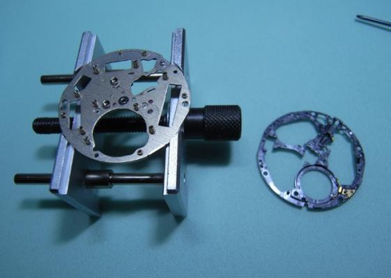
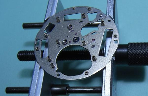
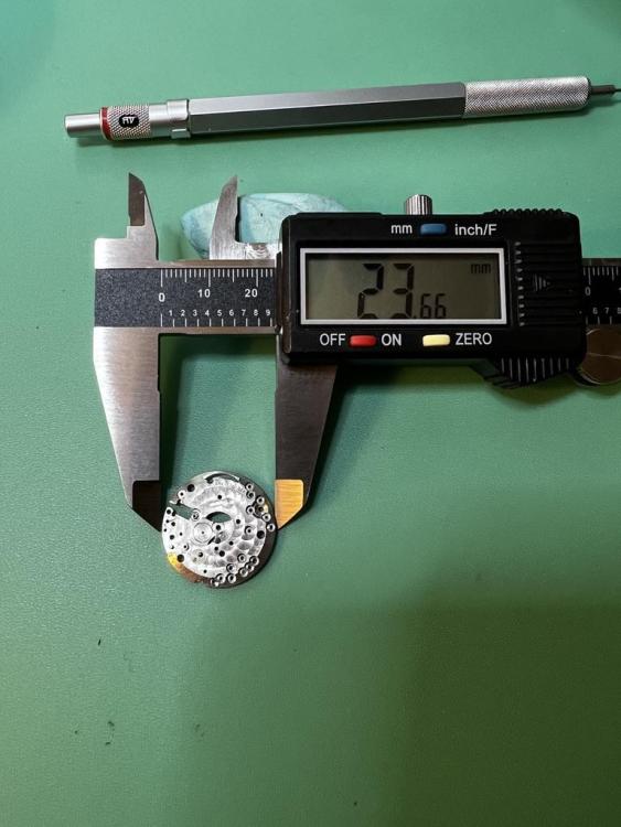
Correction to earlier post. I measured the mainplate correctly but then quoted the wrong number. The diameter is 23.66 NOT 26.66. This means that the movement is 10.5 ligne.
 0 points
.jpg.12df1cc5bc49cce61ed52f98d4c6674f.jpg)
.jpg.d4a1622c7299378df4c37abf9b8778ef.jpg)