Leaderboard


Popular Content
Showing content with the highest reputation on 12/13/23 in all areas
-
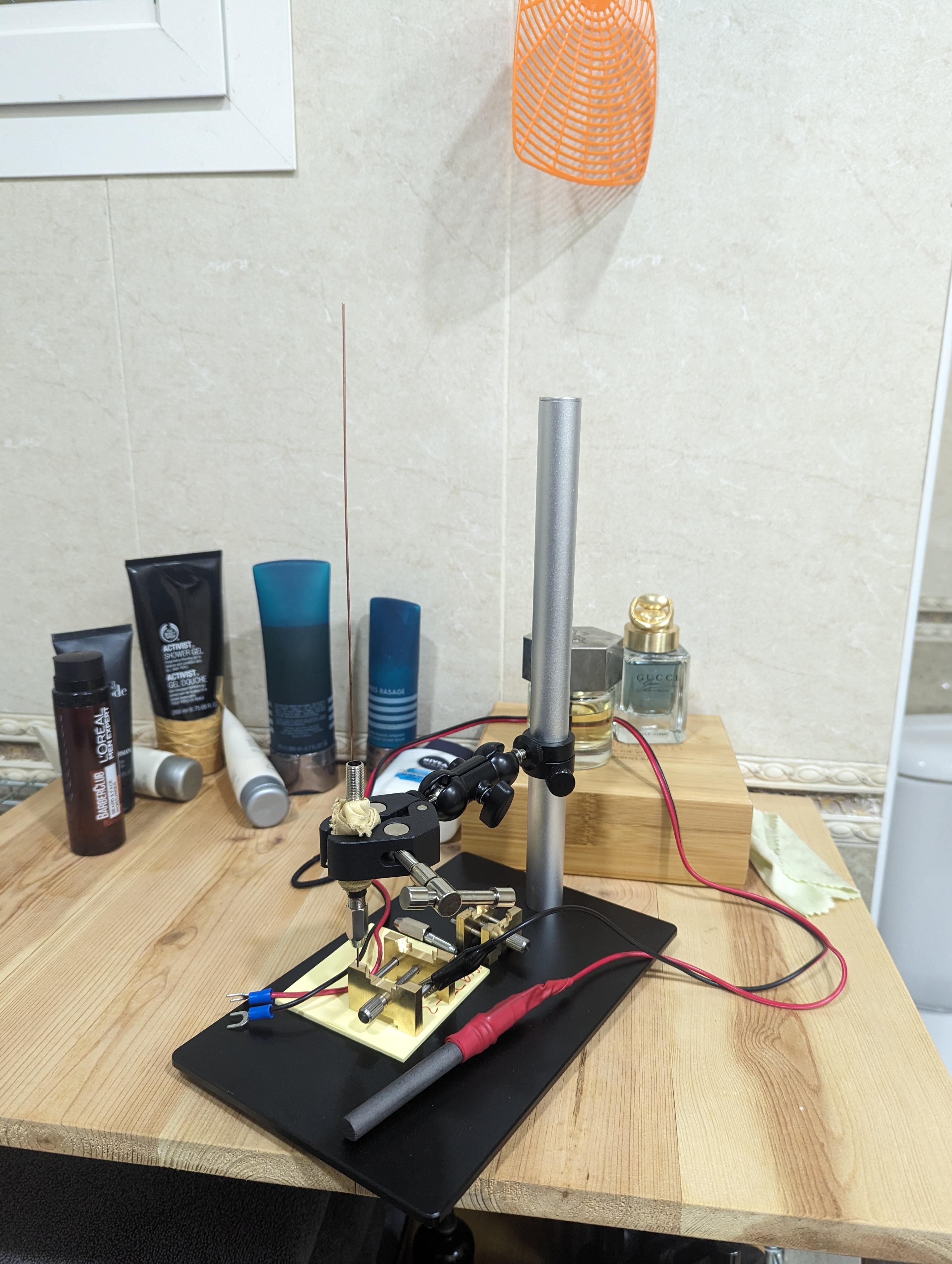
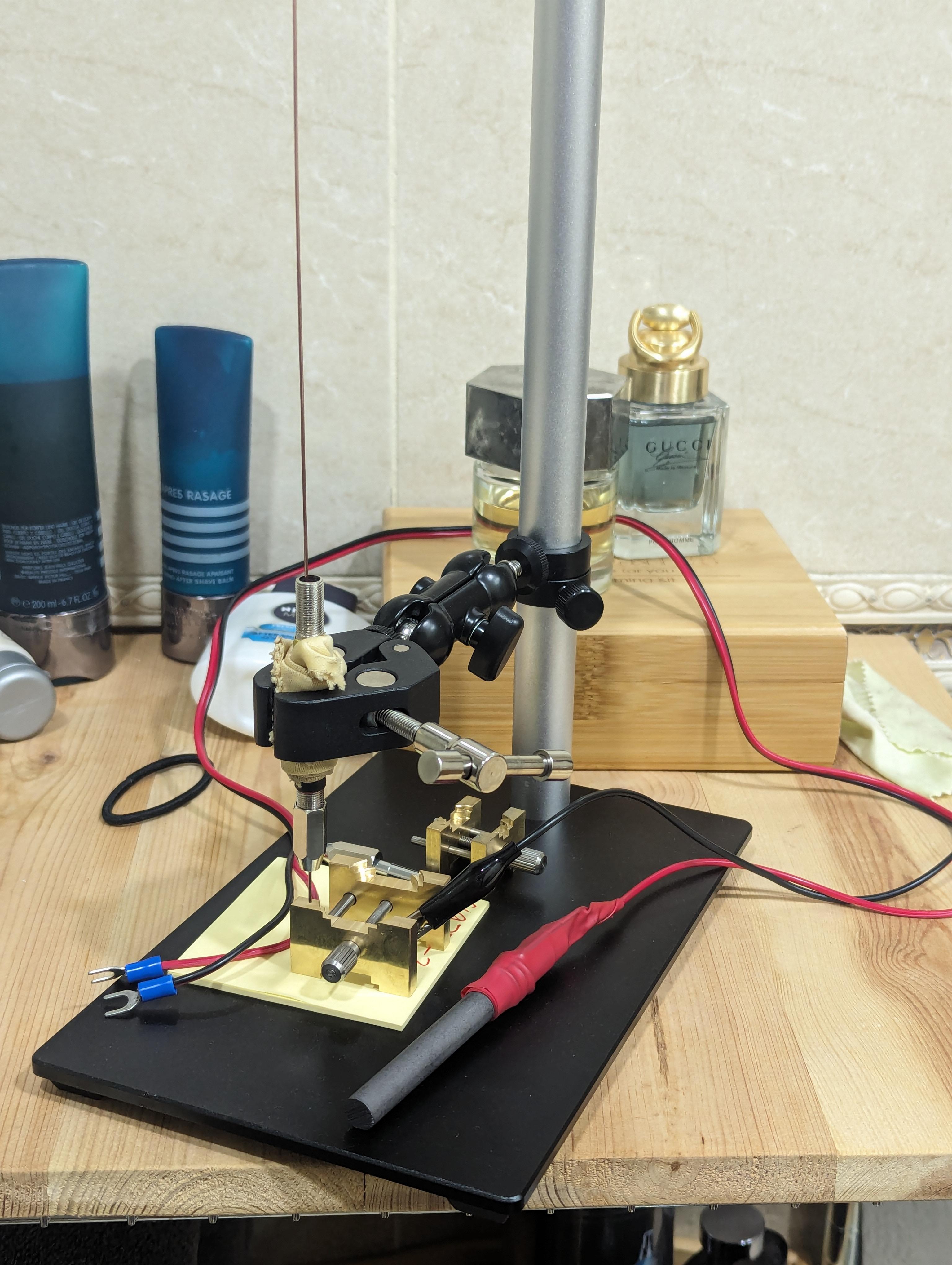
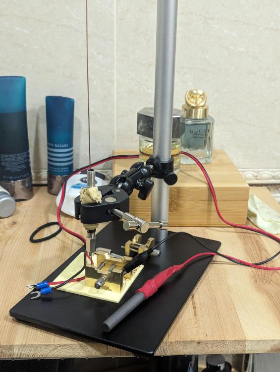
Ross, et al., Here is my home made system: The stand is from Ali Express, it is supposed to be for a digital microscope, the jaws are a little too large, hence the rag to bulk up the OD of the pin vice so the jaws can grip it securely (temporary solution). The copper wire (dial foot to-be) is gripped in a standard double ended pin vice, with the upper jaws of the pin vice are removed so the wire can be fed through the body of the pin vice but still gripped securely in the bottom set of jaws. I put three or four layers of heat shrink on the outside body of the pin vice (under the rag in the picture) for grip and electrical insulation. Then I have 2 brass movement/dial holders (one large and one small) to hold the dial (also from Ali Express). Finally, I have a graphite rod as the anode with some 1 mm copper wire wrapped around it (you can just see the shape of it under the red heat shrink) and then heat shrink to insulate and keep the copper wire in place and then I removed the alligator clip from the anode and joined the anode wire to the copper wire on the graphite rod...with more heat shrink to secure it in place, then connected the cathode alligator clip to the brass movement holder as the electrical return path. The post-it note pad is just temporary, I have some silicone mat on order to replace the one currently on my desk, then I will cut up and use my old desk mat to glue over the base of the stand where the post it note pad now sits for grip (stop the brass movement holder from sliding around) and electrical insulation. Modes of operation: I have a lab DC converter so I can use electricity to from a circuit by touching the graphite rod to the copper wire, creating heat to melt the solder paste on/around the copper wire where it touches the dial I can remove the alligator clip and put the wires away, and then raise the pin vice and then apply heat directly to the copper wire (about 3-4 cm above the dial) using my micro torch (when MRs W is not using it to make crème brûlée) which will heat the wire and conduct the heat down the wire to melt the solder paste at the dial/copper wire interface Let me know what you think

 4 points
 -
All, thank you so much for your input. It's amazing how just talking about these things helps. Can I just make a schoolboy correction to my own notes so far on this. The wheel causing the problem is the fourth wheel (220) not the third as I have been saying previously. I have no idea why I said 3rd when it is as plain as the nose on my face Nicklesilver - you will be pleased to hear you hit the jackpot. Who ever had serviced this last time had put the fourth wheel in upside down. Putting it in the right way up gives plenty of clearance from the intermediate wheel and it runs like a dream3 points
-
Agree completely with your comments, if I get stuck my first point of call is an internet/YouTube search, followed closely by a post here, whilst I am waiting for one of the gurus on here to respond I will turn to the books. The other way I use the books is to dig a little deeper on something I already understand (or think I do!). So I use the books as a learning tool or backup to the internet, If I had to learn something new from them I'd find it very difficult if not impossible.3 points
-
All reassembled, working and running great. Thanks for the help, once again!
 3 points
 -
Exactly, I have no intention of selling this clock. I bought a cheap movement to learn about clocks, followed up with a pendulum and suspension spring and after disassembly, cleaning and reassembly managed to get it working again, albeit not correctly. With advice given by all contributors I have a working clock of value mostly to myself, and learned quite a few things in the process. Not a lot of money changed hands for these parts so I don't mind if it is a Frankenclock. This is my first few steps into this field but not the last.2 points
-
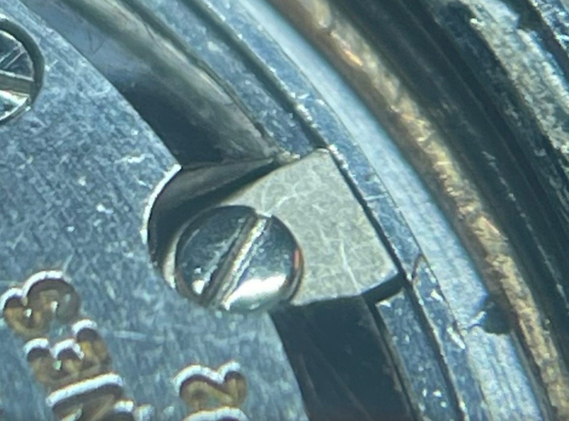
I'd like to revive this thread with the tale of my recent descent into madness. My friend asked me to service his '60s Longines Flagship. It had been sitting in his drawer for the better part of a decade as he wanted to start wearing it again. The crystal was yellowed and badly scratched, the stem had more rust than thread, and the watch would stop intermittently. No problem, I thought. I ordered a range of crystals, a NOS stem, and fixed the centre wheel's tendency to rub on the barrel. Skipping forward a couple weeks, parts had arrived and I was delighted to see that the tension ring crystal fit the case perfectly. My problems began when casing the movement, though. A movement ring is fastened to the movement with two tabs and rests in the case on a shallow lip. Above the movement ring, a brass tension ring shaped like a C is forced into a slot in the case to hold the movement firmly in place. Here's a picture from disassembly: Although fiddly, the process of installing these components didn't raise any red flags... Not until I realized that the movement sits around 1 mm deeper in the case than I'd expect. This is obvious when looking through the crown hole -- the stem would have to jut out at an angle to fit into the keyless works. Cue multiple days and several hours of fiddling and head scratching and, admittedly, some swearing. This small misalignment didn't make any sense, and I was starting to doubt my sanity. Eventually, eureka. I had picked up the wrong case from my drawer. The case I had in my hands was for a Certina movement. Many stars must have aligned to mock me, because the crystal diameter for these two cases is identical to within 0.1 mm, and most of their internal features like lips and slots are very similar. If it weren't for the slight discrepancy in movement resting height between the two cases, I would've never realized that I had goofed up. Lesson learned: stay organized. Label everything.
 2 points
 -
I have had one or two watches where the dial (and in turn the movement) rests on the tension ring, if the ring is removed then the watch dial/movement can move forward and clash with the crystal. In these cases the tension ring is acting kind of like a movement ring or clamps you would find in normal watches. Only come across it a few times, but thought I would mention it.2 points
-
I assume that the volume of the gasket doesn‘t fit the volume of the annular gap. The rubberlike Arnitel material (thermoplastic elastomer) can be deformed easily but is not compressible. Therefore I would try gaskets with smaller diameter in order to reduce the thickness by stretching.2 points
-
Quick update on my fishy watch: I replaced the capacitor last night and then placed the watch onto my automatic winder over night to 'charge up' Put on the watch this morning and everything seems to be working well - haven't cracked the back since last night, but suspect the fishy smell remains2 points
-
I have to agree with you here. Understanding books by for example De Carle and Fried takes quite a bit of effort, and some of the material is no longer relevant or relevant to the areas you are currently interested in. Also, as a beginner, it's difficult to assess what's relevant and what's not depending on current practices and what you're trying to accomplish. Without the Internet, I'm not at all sure I would have managed to get as far as I have.2 points
-
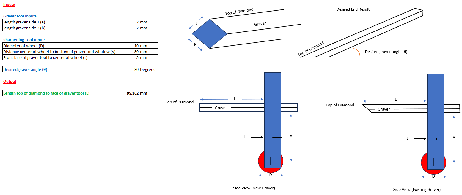
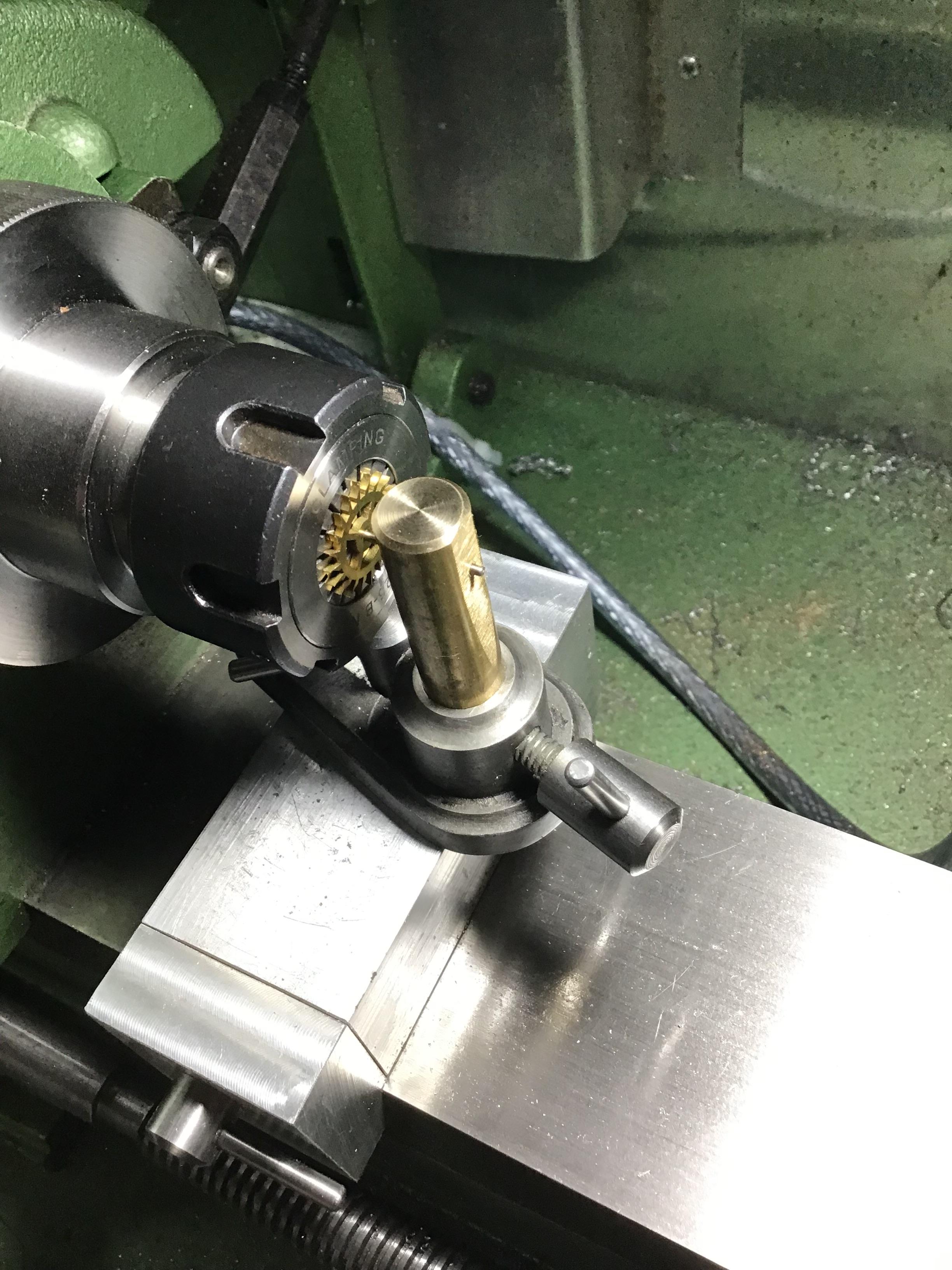
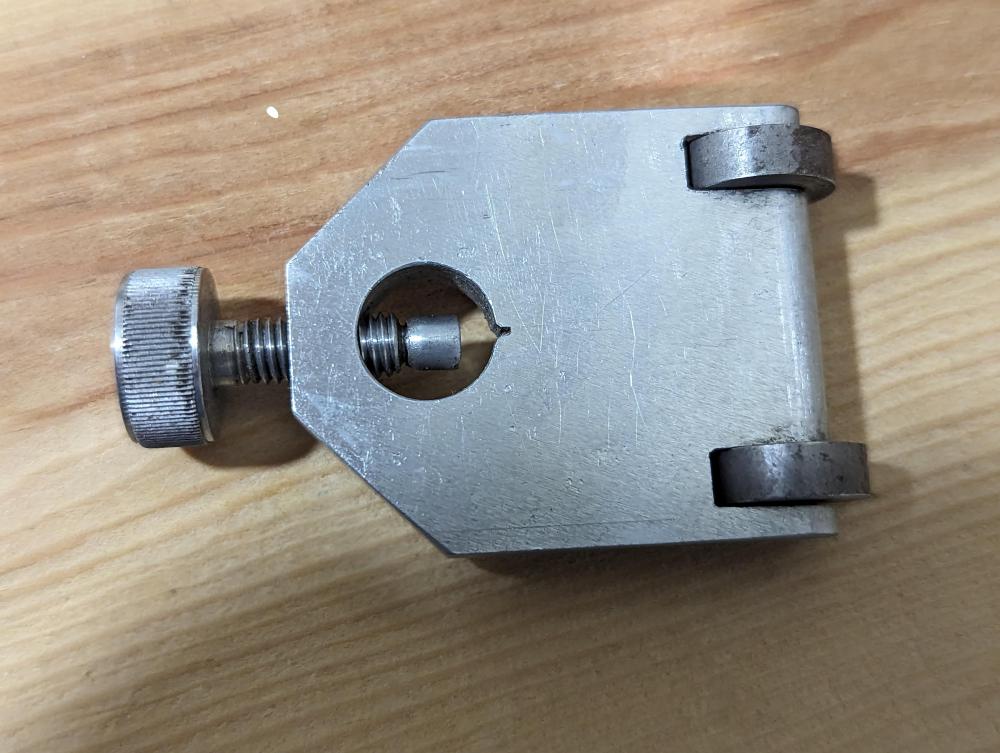
I am about to start on my journey with a new lathe, and need to make some gravers. I ordered the steel to make them and the sharpening stones etc. and planned on making a 45 degree, 20 degree and 30 degree tools to get me started. Luckily I snagged a graver sharpening tool in a recent tool job lot buy so I'm off to a good start. I was pondering how I could get the correct angle for the sharpening process and pictured myself trying to balance everything and try to read a protractor and thought there must be a better way.... here is what I came up with: So all I have to do now is put in the dimensions of my graver and graver sharpening tool (should only have to do once) and the angle I want, and the sheet will tell me the distance (L) from the tip of the top of the diamond to the front face of the graver sharpening tool, so in the example above (fake graver sharpening tool dimensions) if I want a 30 degree angle on the graver I need to have 95.162mm of graver sticking out, then file file away! Turns out my maths teachers were correct, I will use trigonometry every day! Can't upload the excel sheet here but can send it to you if you want it, just pm me with your email. PS Just realised that the model only works for square gravers ie a = b on above drawing - head is hurting from the maths to make it work for non-square tools also. Model also assumes that the angle where the graver enters the graver sharpening tool is 90 degrees.
 1 point
 -
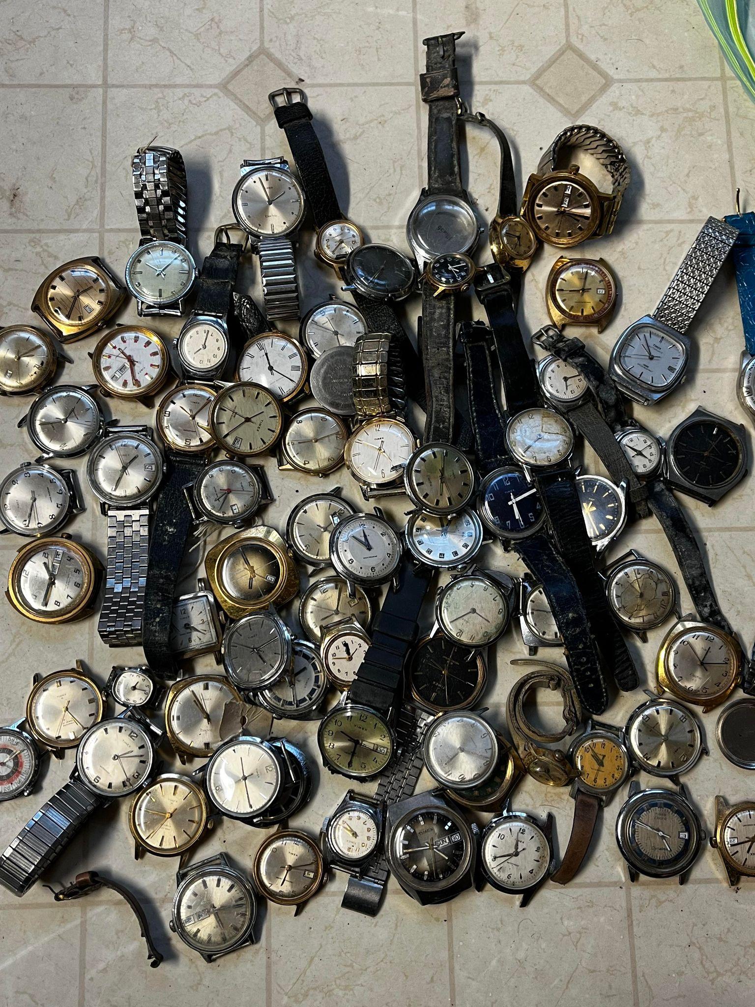
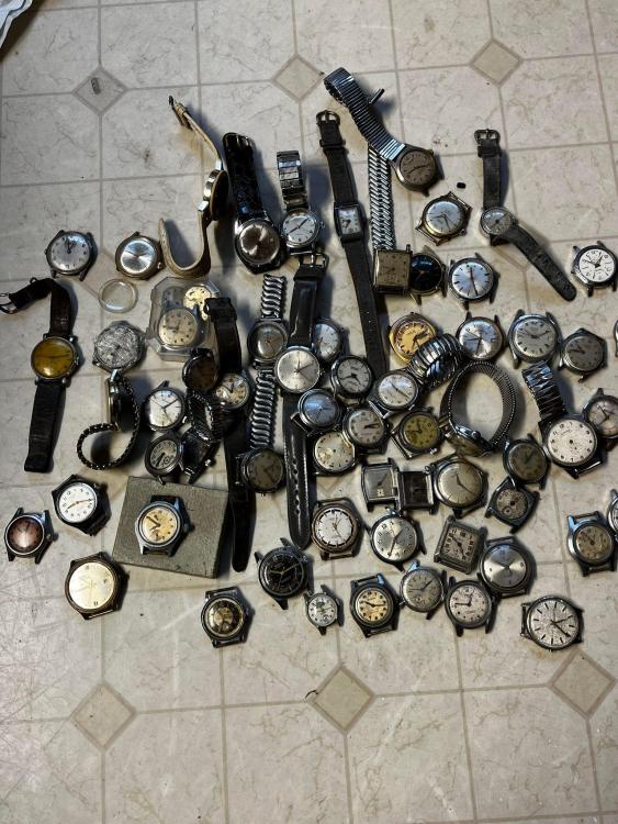
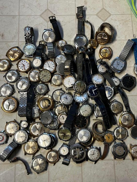
old friend told me he had some stuff I might be interested in. So I said sure lets have a look and I bought them Guess I'm going to be busy!
 1 point
 -
Ok, maybe I was not clear. @ManSkirtBrewyou are correct. I just pried it off. The whole unit comes off as @HectorLooisaid but that was not what I really needed to know but was the correct guidance. I have a donor, but I see that the finger is bent around the collet making it too short to hit the index wheel. I have removed the finger from the plate. Next, I will straighten it so that it will intersect the index wheel properly. But will wait until tomorrow when I am fresh!1 point
-
Welcome to the WRT forum.1 point
-
Welcome to this great forum! Have fun!1 point
-
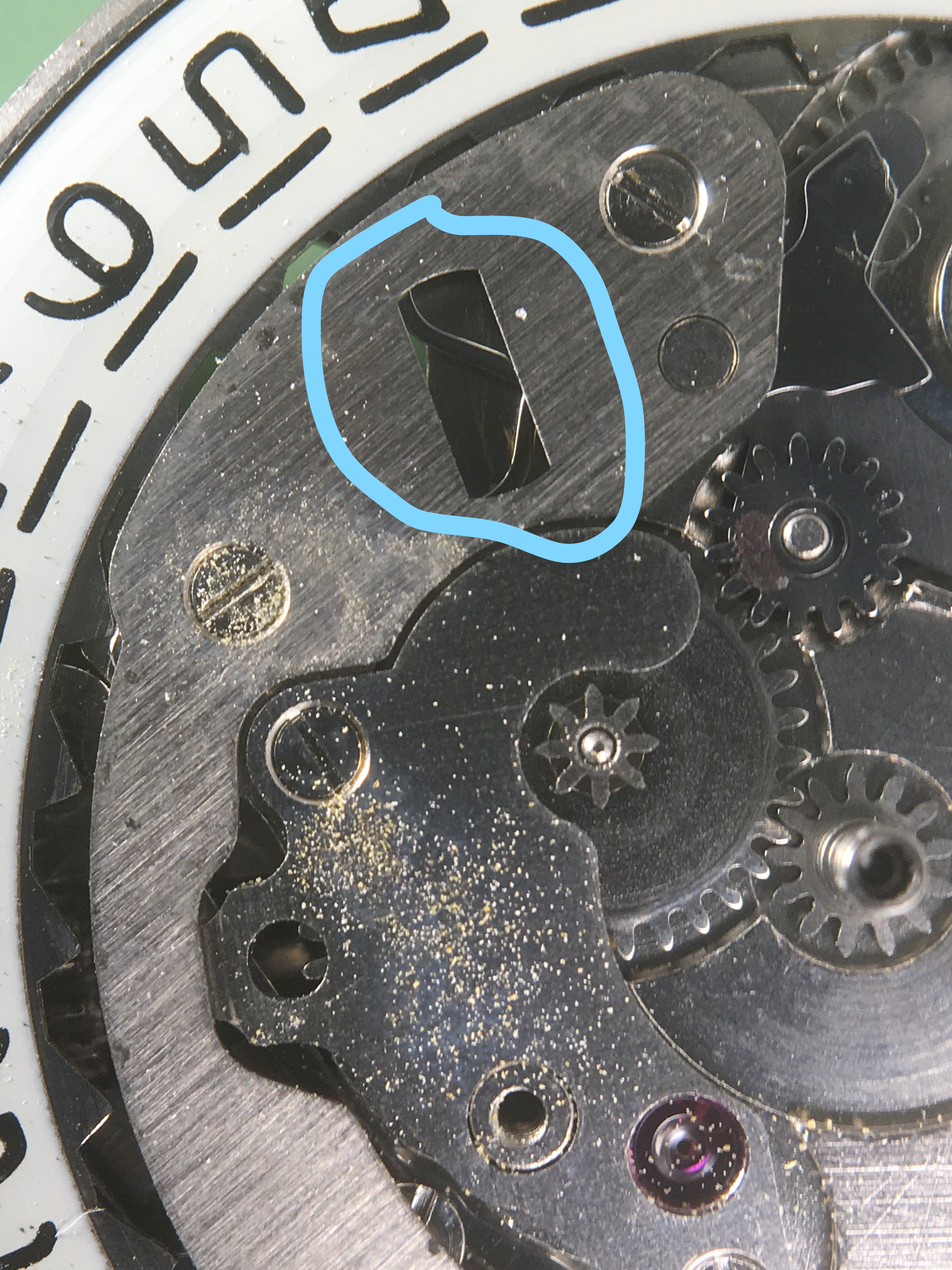
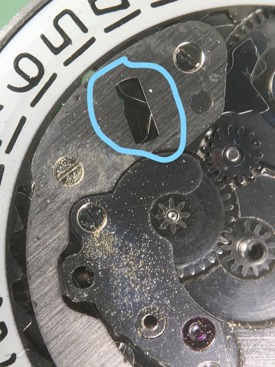
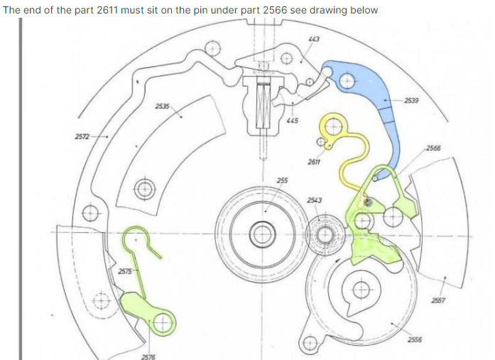
Hi All I'm a beginner trying to get the calendar works to function on this PUW 1561 (pics taken before cleaning). The date advances when the crown is pushed. I've lined up the highlighted parts as best I can but it's not working. It's very fiddly to get the pin on the "driving wheel for date indicator" part 2556 to stay to the right of "date corrector spring" part 2611 as is shown on the diagram. There's a cutout on the retaining ring that I suspect is there to make the job of getting this right easier. However, I'm not seeing what needs to be done within the cutout. Any help would be greatly appreciated! Charlie Helpless in Maryland.
 1 point
 -
Hello and welcome from Leeds.1 point
-
May be just trueing hte wheels is needed. As stops ones per 4 hours, then the intermediate wheel is not perfectly trued - it makes full revolution for 4 hours. Then, look at the intermediate wheel bearings - they may have weared and the wheel may not stay upright.1 point
-
Some more pics would help, are you sure you have the 3rd wheel (and everything else) the right way up? Sometimes you can actually put wheels in upside down and they almost work.1 point
-
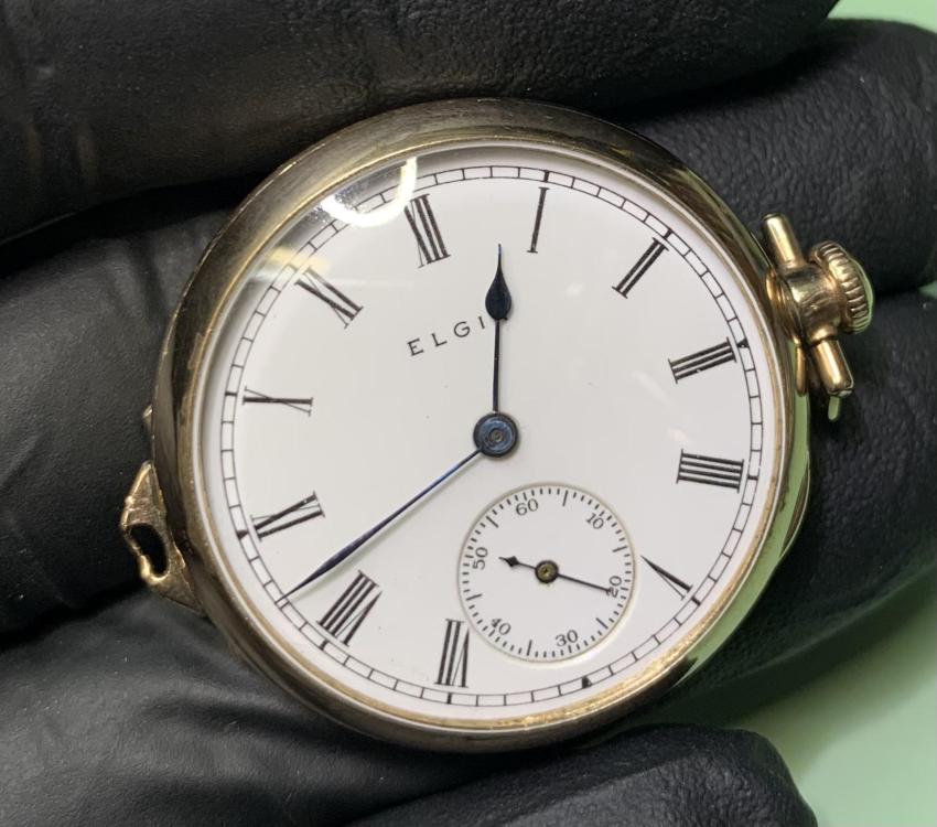
welcome. How do you say pocket watch in your language ?1 point
-
Thank you for your introduction and welcome to this friendly forum. We all look forward to your contributions and continued involvement. Emanuel could you use English please.1 point
-
Hello and welcome from England.1 point
-
Welcome to the forum, enjoy. por favor corresponda em inglês1 point
-
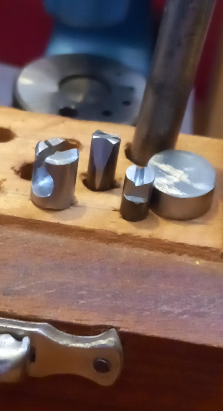
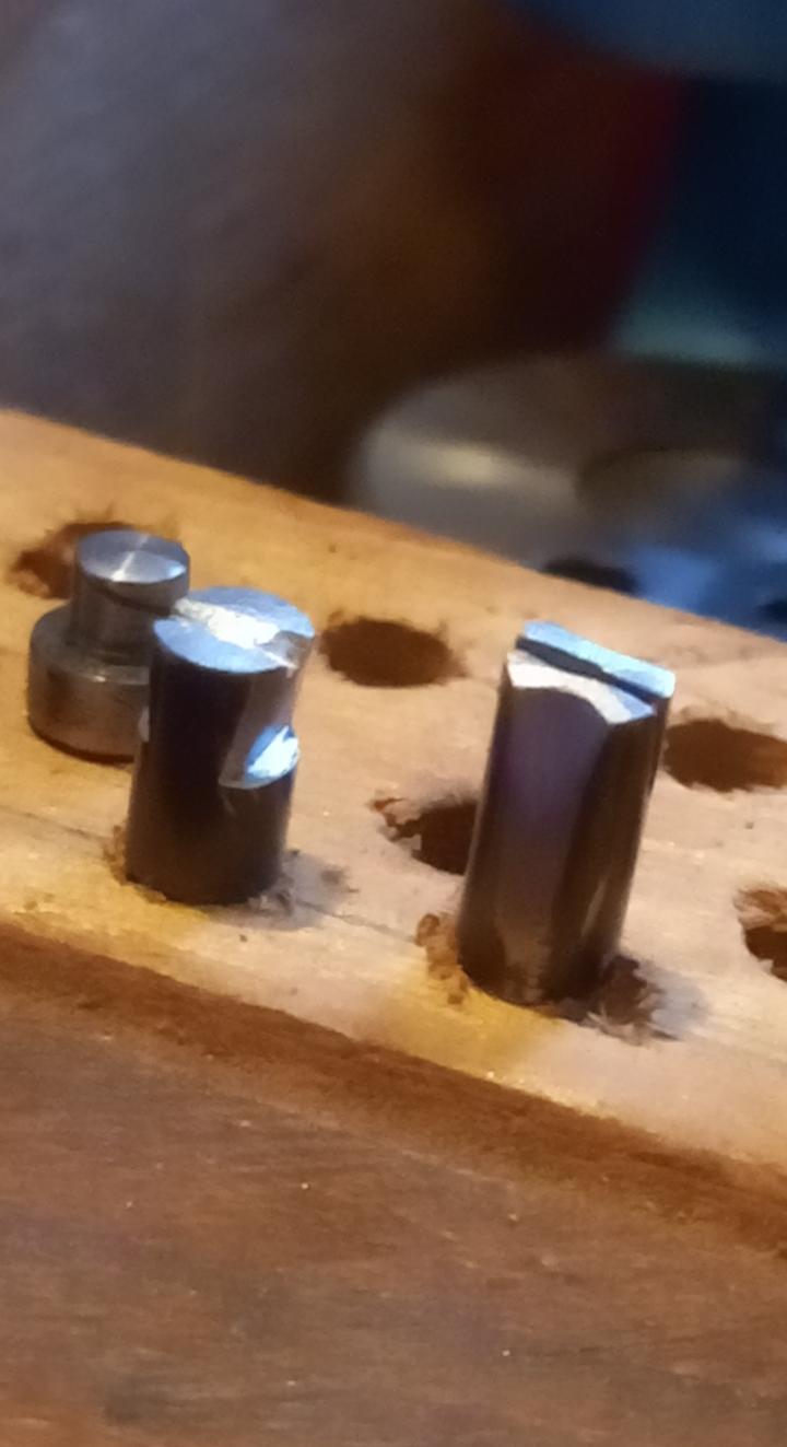
Have now made 4 stumps. Think I will rest for a while. Time to get back to watches. Large 10mm base 4mm for pinion 6mm for balance staff removal

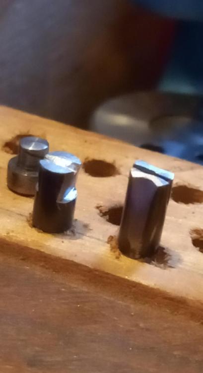 1 point
 -
A little for me too, I'm not an electrical engineer - so only 90% sure I won't fry myself when using it. Will have to wear my rubber boots when using it. But seriously, if anyone sees any potential issues, please let me know!1 point
-
Ah I missed the stamp . It was perhaps a blank arbor to be turned/drilled as needed; it would be less hard (or unhardened) in that case.1 point
-
Good for you. We all have to learn.1 point
-
I seem to remember that lathes spindle has a thread if so then you could get or make a backplate and get an ER chuck to fix to backplate like I have on my Myford although it’s larger than your lathe , at the very least it would get you going while you look for collets. Dell
 1 point
 -
Yes and no, because the length is referenced to the top of the diamond, the tool will first start to sharpen on the bottom tip and the graver will be sitting at the 'wrong' angle eg 28 degrees, as the tool face wears during the sharpening the error in angle will reduce until, just as you reach the tip of the top of the diamond it will be exactly the angle you want - ie 30 degrees in the example above. Now where is the fun in that?1 point
-
You sure like to make life hard. Why don't you buy them already sharpened.1 point
-
It seems to have a thread in the bore? Could be for holding cement brass pieces, that get heated and hold parts with shellac. Might not be Moseley either; they had their "conoidal" taper which was a curve, and also more standard 20 degree head taper, but long compared to standard collets. This has a homemade aspect to me.1 point
-
I have nothing but admiration for you and your ilk. How you learned is great anathema to me. I have 3 books on watchmaking and have not understood beyond the foreword. Even now, after two years of practice I struggle. I have always learned visually and physically. I see, I learn, I do, I learn. YouTube and the internet courses have allowed me to understand and at this stage be able to work on watches , not with great skill yet, but as a result I can practice what is preached by others. Thank goodness for you and colleagues of your standing who give so much to us novices. Don't stop. Regards Toss1 point
-
Haha, most of the watches I have worked on have the waterproof characteristics of a paper bag.1 point
-
Whilst I totally agree, no one realised in the past that things were difficult, it was as it was. We all remember the Yellow Pages or other nationalities equivalents, we knew no better or at least had no other option. The Internet has made searching things much easier and videos to watch, instead of 2d drawings are a great help, also cheap ( at least relatively) microscopes, make life easier. The skills of watch repair though, haven't changed for hundreds of years.1 point
-
Thanks. While most of the watches I work on claim to be waterproof, I’m pretty sure that this was just 1950s marketing hype (even if fitted with tension ring crystals). I seem to recall the US cracked down on these claims sometime in the 1960s…1 point
-
May go down that route eventually. But am just beginning my journey on dial repair and this is a cost effective way for me to learn. Two more tools. Watch hand closing tool and a screw removal jig. Oh, and Fried book. Roll on Christmas.1 point
-
Looking at this, do You think that shorter suspension spring can be fitted? I don't think so, or with modification of the crutch... See, the OP has already bought this thing and we here can just guide him to make it work normally, wit no need to buy more parts. This is absolutelly possible. Just some shortening hte entire lenght of the pendulum is needed. Shortening the leader, of course, is possible. It should be done from the down side of it, between the hole for the crutch and the hole for the pendulum hook. The pendulum hook itself can be shortened, and it is easier.
 1 point
 -
Good point. If they ask for money don't touch them. It is unbelievable the amount of phone calls I get all from scammers. I lead them a merry dance then tell them to *uck off. Half the time you can't understand what the bugger say.1 point
-
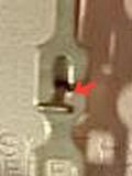
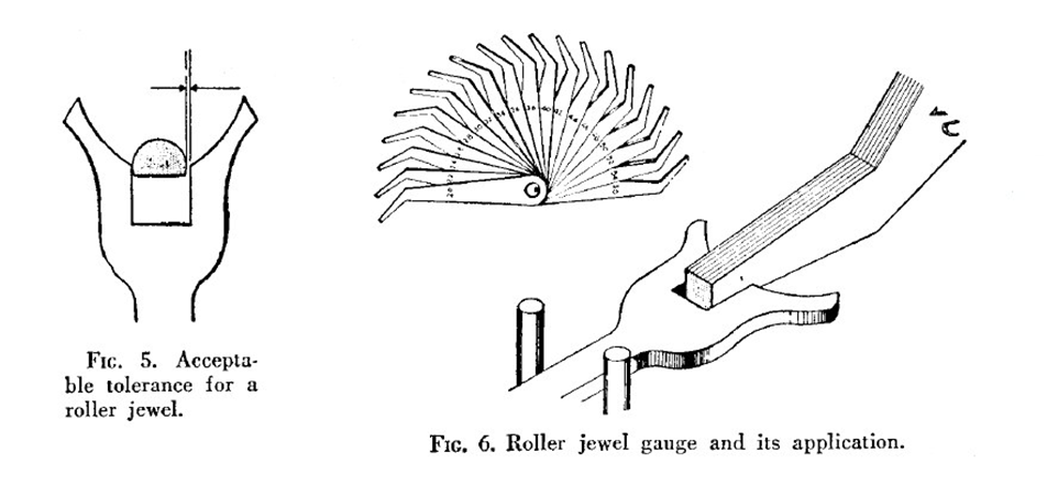
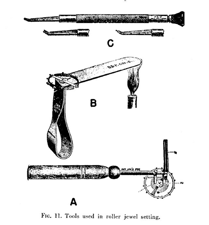
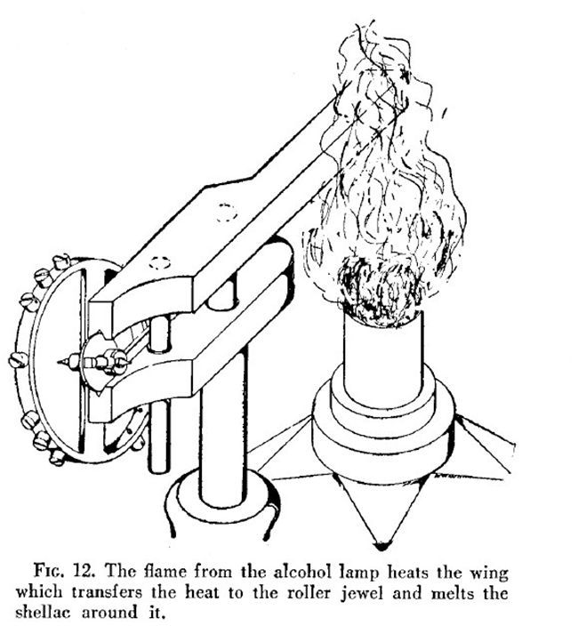
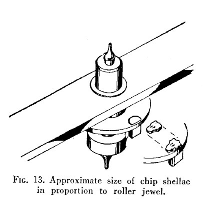
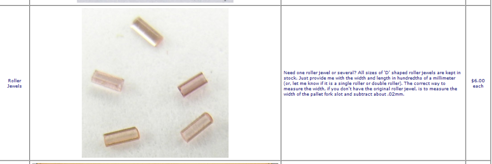
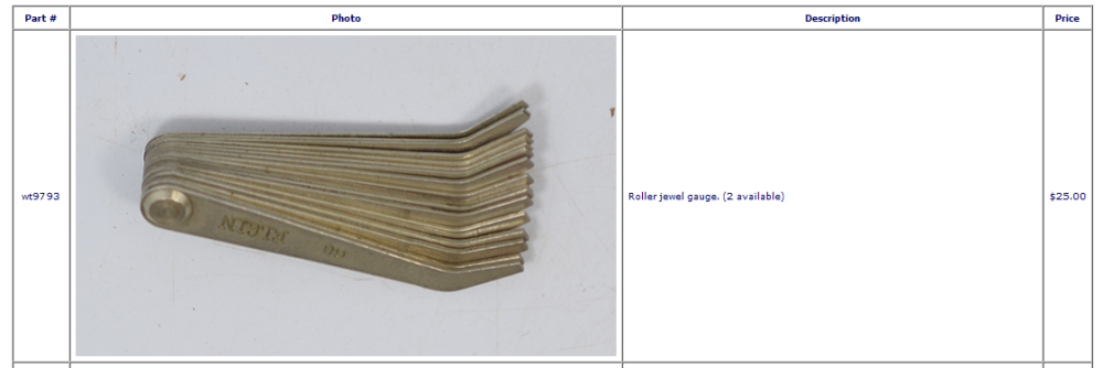
One of things I always like to do with incoming watches and you're making an observation the watch is not running but if you get the balance wheel to rotate you always look to make sure that the pallet fork is moving. It's actually quite common on pocket watches for the balance to move the pallet fork not because of roller jewel missing.. Then from the look at your balance wheel it appears to be a single roller versus a double roller watch? The reason I bring this up is single roller watches require longer roller jewel's so often times modern assortments will not have a jewel long enough. Then it's so sad the roller jewel's been stolen by a previous watchmaker and now we have to throw the whole watch away because you don't have a roller jewel if only there was something you could do? No murdering another watch to seal its roller jewel is not an ideal solution.. If only we were dealing with watch repair we would have something to do like replace the roller jewel? Then yes occasionally have a weird sense a humor it's based on your research and the outcome of your research that you get a weird paragraph up above. Then we're going to need some tools and a few more tools after that plus it be really nice if the ruler was unfortunately broken off rather than falling off because that means there should be a little piece left that you can measure. Otherwise we have to do it the other way So if you don't have the old jewel you need a roller jewel gauge they, of course in a variety of styles and shapes you could use a machinists or an automobile shop feeler gauge. In other words you need something to stick in the slot and measure its width and then the jewel is just a tiny bit smaller. We also need some shellac and roller jewel of the suitable size and a heck of a lot of patience to get up to go into its hole. Then yes they do make special tweezers reporters but you still have to get the roller jewel into those so doesn't really matter the roller jewel is a pain in the something to get into the hole. Then a variety of tools to hold it when you heat up and apply the shellac. Then once the shellac smelted in the jewel is not go fallout you can gently straighten it out and get it where it's supposed to be. Here's a better picture of the tool for holding newly roller table.. You will also note this is a double roller watch shorter roller jewel Yes the pictures make it look so easy Then looking up to the assortment a roller jewel's is a good thing to do I done it before except of course it helps to have the right assortment like a vintage assortment versus a modern assortment or what about this website? Let me just snip something out for you Then on another page he has one of these Okay this will get you started
 1 point
 -
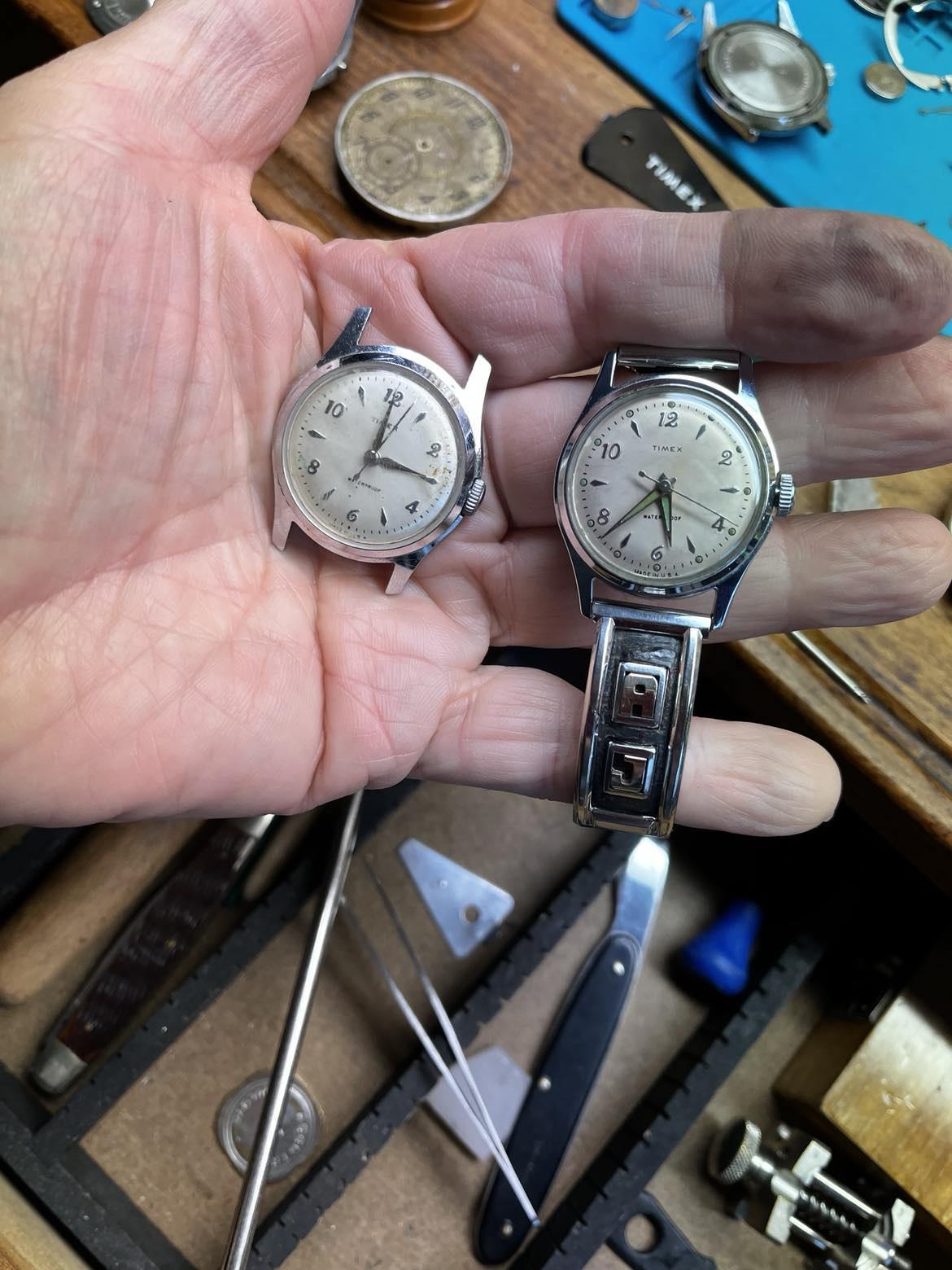
here is the first completed project from the lot - cleaned up and polished the "A J" band. Switched it over to a working 57 Marlin. Will have a look at the one it came off of and get them back together.
 1 point
 -
With the date wheel, date jumper (2576), date jumper spring (2575), 2611 out of the way install 2539 and 2566 as shown in your diagram. Then using a piece of peg wood to keep 2566 in place hold the pivot end of 2611 in your tweezers and feed the free end in under 2566 so that the end of 2611 is positioned correctly relative to the pin on the under side of 2566; keep the pivot end of 2611 to the right (as per your drawing) of its pivot post whilst you do this so that it isn't tensioned. Then carefully push the pivot of 2611 across and onto is pivot post whilst still keeping 2566 in position with the peg wood. Once in position it should all stay put unless you jolt it, whilst you drop the date ring into place. Then install the date jumper, followed by its spring. To install the spring drop it over its post so that the short leg is in position and the long leg sits on top of the jumper, hold it in place with peg wood sitting on top of the post and the short leg, and then use tweezers to position the long leg behind the jumper. You can then install the keeper plate. It sounds more complex than it is but I've just done it twice as described with no issues.1 point
-
Just a little side note on this - a lot of watches (with the ETAChron system) I get in have this problem: If you get a lot of positional error (sometimes by as much as 15secs/day differential) after service then check the index pin. If the hairspring is bouncing between the two pins then this 'could' be the cause of the positional error. Time and time again, I have turned the pins (from the top) until the inner pin is just touching (and effectively arresting) the outer coil of the hairspring, and with some tweaking, completely eradicated the positional error and getting a near perfect straight line in all major positions on the timing machine.1 point