Jump to content

Aircraft Clock


clockwatcher

Recommended Posts

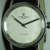
As many of you may be aware I am a bit of a 'Jammy Sod'! The latest bit of jamminess is as follows. I was helping his widow to clear out my late friend's shed and was asked to divide the contents of a bag of 'scrap' between two bags, as the one bag had become too heavy to lift. It was destined for the metal recycling bin at the local dump. In transferring the contents I came across the clock in the pictures. Reporting it to my friend's widow as I was obliged to do I was told "If you want it, have it!"

The dial bore the stamped maker's mark 'S. Smith and Sons (MA) London' and the applied marking L 3/39, the date of manufacture or issue I presume. Some investigation online suggested that it was supplied to the Air Ministry and elsewhere as an aircraft clock. The 12-hour dial has alternate lumed numbers and lumed minute and hour hands for both main and subsidiary dials. The lume on the hands is completely shot but, although spent, the hour lume markings are crisp and largely intact. There's a 12-hour Time of Trip subsidiary dial and a sweep second hand. The trip timer and second hand are activated by the right-hand button and are both fly-back. The chrono function can be disconnected by turning the middle button where a small circular window shows red or white, off or on. The left button is for winding/adjusting and hacks the movement. The clock runs well but will benefit from a service. The timer function runs for a few minutes and then stops but I think this is due to lack of lubrication, after all it's probably never been opened in 75 years!

There's no indication on the outside as to what movement is lurking inside and I naturally presumed that it was made by Smiths. Imagine my pleasure in removing the casing and discovering a 13-jewel Le Coultre movement. It's a gilt beauty and absolutely immaculate.

Am I pleased? You bet!post-742-0-50552600-1448213908_thumb.jpgpost-742-0-64091500-1448213939_thumb.jpgpost-742-0-32012500-1448213961_thumb.jpgpost-742-0-32146300-1448214357_thumb.jpgpost-742-0-39789500-1448214403_thumb.jpgpost-742-0-28743200-1448214440_thumb.jpg

  • Like 2
Link to comment
Share on other sites

  • 2 months later...

Very nice, I've a friend with one of those, he won't sell it .

I got one of the more basic ones, got it from a fleas market ,as a non runner.

Broken winding wheels, I managed to repair it eventually.

It turns out it came out of a hurricane aircraft, I made a stand for it and now it sits on the side in the spare room.

Pictures if any wants me to try posting them.

  • Like 1
Link to comment
Share on other sites

Well , I'm not happy about the screws as there new cross head screws awfull, I will get around to making up a piece to cover the screw holes and a clip to finish them off.

No doubt broken when it was removed from the plane.

The holderi made by simply slotting the angled piece of wood into the lower part and simply glueing it in.

I made a larger stand for a smiths bulk head clock, it was my second effort turned out much better.

Link to comment
Share on other sites

Just a thought but if you wanted to you could fill the cross groves of the screw heads with solder and then paint over the top of them.  If not solder, then common epoxy filler will do the job.  To paint the ends just go and buy a black paint marker from a stationery shop.

Edited by stroppy
Link to comment
Share on other sites

  • 2 weeks later...

Join the conversation

You can post now and register later. If you have an account, sign in now to post with your account.
Note: Your post will require moderator approval before it will be visible.

Guest
Reply to this topic...

×   Pasted as rich text.   Restore formatting

  Only 75 emoji are allowed.

×   Your link has been automatically embedded.   Display as a link instead

×   Your previous content has been restored.   Clear editor

×   You cannot paste images directly. Upload or insert images from URL.


  • Recently Browsing

    • No registered users viewing this page.
  • Topics

  • Posts

    • It looks like the canon pinion function is part of this great wheel. The pinion nearest the clip runs the minute wheel on the dual side. The pinion nearest the wheel is driven by a small wheel from under the setting lever cover plate that engages in hand setting position.    So when assembled the crown was driving the whole great train. Does this mean the pinions are too tight? Should I attempt to disassemble this great wheel and lubricants?
    • Picking up this side-tracked post again as I just removed a balance staff of a 1920's Omega (35,5L-T1) I was impressed by the way @Delgetti had his setup when he had to change out a balance-staff (https://www.watchrepairtalk.com/topic/28854-new-balance-staff-not-riveting-to-balance/page/2/#comment-244054 Not only that, but also the idea of removing the seat first before punching the staff out from the seat-side, avoiding the whole discussion of the rivet yes/no enlarging the hole. I didn't have the fancy clamps & tools Delgetti has, so I used my screw-head polishing tool. Initially I used #1500 grit diamond paste on the steel wheel, which kinda worked, but very slow. I changed to #800 grit diamond paste, which worked better, but still slow. Then I glued #240 sanding paper to the steel disk; That worked and the disk was hand-driven. Once close to the balance wheel, I took the sanding paper off and continued with #800 diamond paste. One can only do this when the balance wheel sits true on the staff and has no "wobble". I went on grinding until I saw some diamond paste on the rim of the balance wheel. This was as far as I could grind and it seemed that there wasn't much left of the seat. Carefully, with my staking set, I knocked the staff from the seat-side out. Turns out that the thickness of the seat left, now a small ring, was only 0.1mm. The balance wheel hole is in perfect shape and no damage done to the wheel at all. Of course, if the wheel has a "wobble" or isn't seated true on the balance staff, you can't get as close and there will be more left of the seat. In my case, it worked perfect 🙂 I'm very happy how this method worked out ! 😊  
    • As is tradition, one step forward, two steps back. Got the board populated and soldered into place without any issues.   But no hum. So I started testing the coils with an ohmmeter. I got 5.84k ohms across D1 (from red to red in the picture below), which is as expected. But I'm getting an open circuit for the other drive coil and feedback coil, D2 and F1 (from green to each of the two yellows).   Since the movement was working with my breadboard setup, it implies I somehow broke the connection between the coils and the solder lugs. They're all the way at the bottom of the lugs, but maybe the heat migrated down and broke the connections? I guess it's possible it happened while cleaning the flux off, but I used a soft artist's brush and isopropyl alcohol. I did a lot of high magnification examination, and I don't see any issues, but let me know if you see anything I missed or if you can think of anything else I should check.
    • 1947 NOS Ambassador 'C'. Actually, the case came without the movement so the movement isn't NOS, but she sure is pretty.
    • Hi attached is the AS 20XX. Service sheet although there is no 2063 mentioned it may be of some use to you AS_AS 2060,1,2,6,4,6.pdf
×
×
  • Create New...