Jump to content

Little French traveler clock


Endeavor

Recommended Posts

Hello All;

Currently I'm servicing a little French traveler clock, measuring 5.5 x 7 cm and has a cylinder escapement. I bought it in 1995 in Melbourne, Australia. The enamel dial shows the inscription of the retailer: " T. Gaunt & Co, Melbourne, French made", so the clock has stayed or always came home again .... until I bought it ?

Since 1995 it has been on "display" or in the drawer, it ran'ish but now it was time to give it a good service.

Couple of questions;

- An age estimation?

- Any other noteworthy information such as commonality of this size or any other remarks?

- I like to open the spring barrel, but I'm not sure what the best method is to take the cover off? Any hints will be greatly appreciated !

IMG_1068.thumb.JPG.48d0db735c128206073d7ef07505d630.JPG

IMG_1069.thumb.JPG.f62d85193fb8ba2075c7c471330beeb6.JPG

IMG_1070.thumb.JPG.05f192861480dd629a001c4b1ce4e9a2.JPG

IMG_1079.thumb.JPG.98dd52fcbf7eb38609ce5d6383b01670.JPG

IMG_1102.thumb.JPG.a1b8b30fa7b475fef51d99443b2935ca.JPG

IMG_1103.thumb.JPG.b586c71e6635d11e7bfe3d9ddb98009d.JPG


Hope to hear ........

Thanks in advance !

Link to comment
Share on other sites

We should wait until one of the clock people come around but I would whack the arbor with a hammer. Make sure it's a brass hammer so as not to put burrs on the arbor.

Somewhere in a watch discussion group this subject came up and apparently and I didn't pay attention to the physics of it whacking to remove the cover sounds harsh but causes less distortion than a slow push.

Then of course there is the notch supposedly that's there for you to pry the lid off.  

Then as far as removing the mainspring goes we got that covered. It's in the video in the link below third-generation clockmaker and? There is even a video of putting the spring back in personally I wouldn't recommend this method.

https://www.watchrepairtalk.com/topic/18704-another-idiot/

  • Thanks 1
Link to comment
Share on other sites

French carriage timepiece around 1870, this is an 8 day with cylinder platform escapement. As you have removed the platform the mainspring has no power. I see the barrel has a punch mark which indicates that the cap can be put back on in the same place. The best way to remove the cap is to hit the arbor, I always used a box wood mallet because you don't want to leave marks, so use something that doesn't mark. You will need a clock mainspring winder to remove the spring, if you remove it by hand then you should replace it with a new spring as the old one will be damaged. 

If you need any more advice just ask. 

  • Like 1
  • Thanks 1
Link to comment
Share on other sites

Thanks, that worked really well !

I just banged the winding part of the arbor a few times on my cutting-mat and the cap popped off.

The arbor was soaked in oil, so I decided to leave the main-spring (most likely pretty "well" oiled as well) in the barrel. All the wheels, escapement and plates are now for an overnight left in the cleaning fluid. Tomorrow the continuation ?

About 1870's ...... hmmm, not bad ! Wondering if any quartz movement would survive 150 years .... ? Probably by then batteries are for environmental reasons prohibited ?

IMG_1104.thumb.JPG.f3680c9e01c46f4e1d877b0ac72d82e1.JPG

Edited by Endeavor
Link to comment
Share on other sites

With all the parts cleaned the assembly could begin.

IMG_1107.JPG.9fe78f8d39d77a078c764958fc42aa9f.JPG

Inspecting all the pivot holes and the escapement, I don't get the impression that the clock has run a lot. The pivot holes a nice round and (to me) the cylinder & escape-wheel look to be in a good shape as well;

IMG_1115.JPG.511ee1aa8fa4a00082cd5ad4a2f7989c.JPG

In order to oil the cap-stone the balance wheel & hairspring had to be removed from the bridge;

IMG_1109.JPG.0b193771bfcaf4ac61591e070a181ffe.JPG

I replaced the balance wheel & hairspring and "pinned" (a small copper wedge-pin) the hairspring back in it's original position.

Completely assembled, with only a small amount of tension in the main-spring I can't say that the escapement runs smooth. Started the balance wheel with a peg-wood, it makes a few ticks and stops. Even though with the hairspring "pinned" as it was, I wonder whether that was correct in the first place?

@oldhippy or any other forum member; Could you please enlighten me on what the position / alignment of the cylinder (in rest) compared to the center-line of the escape-wheel should be?

Hope to hear ?


Link to comment
Share on other sites

Aren't you going to polish all the brass parts. 

Have you checked all the teeth on the contrate wheel that is the wheel that connects into the escape wheel. You might have the platform out of line, you also have an adjustable depth screw for the contrate wheel on the back plate. This is the part marked in red.

IMG_1107.JPG.9fe78f8d39d77a078c764958fc42aa9f.jpg

Link to comment
Share on other sites

No, I'm not going to polish the brass parts. I know they have in the UK Horolene. For years CousinsUK was not allowed to ship it overseas. Now they are allowed, but with Britain out of the EU the EU Mafia authorities penalizes everybody heavily who does any business with the UK. Above the 80DKK (£9.25) and I'll get hit with £21 registration fee + import-duty; that is as a starter !! Now, each time I order from CousinsUK, it can only be small parts or split orders to stay below the £9.25 per order, but obviously pay the multiple postage extra. Above the £9.25 and I've to source the items somewhere else, against higher cost !  ???

So for now I'll leave the brass "as is", but thoroughly cleaned.

I adjusted the platform already and there is only a tiny axial play in the contrate wheel shaft. Please remember that on top of my post I mentioned already that the clock wasn't running great. If the opening of the cylinder is "out of line", that may explain a lot(?) My question remains; what is the correct cylinder alignment compared to the center-line of the escape-wheel ? It would be very nice to know that ?


Edited by Endeavor
  • Like 1
Link to comment
Share on other sites

15 hours ago, Endeavor said:

No, I'm not going to polish the brass parts. I know they have in the UK Horolene. For years CousinsUK was not allowed to ship it overseas. Now they are allowed, but with Britain out of the EU the EU Mafia authorities penalizes everybody heavily who does any business with the UK. Above the 80DKK (£9.25) and I'll get hit with £21 registration fee + import-duty; that is as a starter !! Now, each time I order from CousinsUK, it can only be small parts or split orders to stay below the £9.25 per order, but obviously pay the multiple postage extra. Above the £9.25 and I've to source the items somewhere else, against higher cost !  ???

So for now I'll leave the brass "as is", but thoroughly cleaned.

I adjusted the platform already and there is only a tiny axial play in the contrate wheel shaft. Please remember that on top of my post I mentioned already that the clock wasn't running great. If the opening of the cylinder is "out of line", that may explain a lot(?) My question remains; what is the correct cylinder alignment compared to the center-line of the escape-wheel ? It would be very nice to know that ?


Hello mate, nice little clock that, as for cleaning you do know that you can use Brasso ( liquid form ) and rinse with lighter fluid to get the plates spotless and shining the same way that horolene does, still have to peg out the pivot holes but it works great

  • Like 1
Link to comment
Share on other sites

Indeed, the cylinder was out of beat, that's to say outside of the 3 markers. Un-pinned the hairspring and turned the balance wheel till I ran out of hairspring, which coincidentally positioned the little balance wheel pin pretty much in the center. Sorry for the crappy pictures ....

IMG_1116.thumb.JPG.089c0ac40bebdbbcf028e076863bd5cf.JPG

IMG_1117.thumb.JPG.8bf2d49300d685913225c1cb3086b58d.JPG

After a slight adjustment to the platform, it started ticking happily on a slight main spring tension ?

However, I'm not home yet. The second coil is touching and rubbing the underside of the regulator boot. It pushes the otherwise seemingly nicely horizontally positioned hairspring down. It's still a bit hard to see on the best picture I could take;

IMG_1119.thumb.JPG.02ffe6fa3bcf25b9627adac7f5b4fa4d.JPG

I'm not 100% sure what's going on?

The possibilities I was thinking of are either something is up with the position / angle of the regulator or the hairspring coils are "bigger" than they supposed be and the hairspring coils have to be manipulated making the sum of the coils or perhaps better said; the total diameter of the hairspring smaller?

If I were to manipulate the hairspring to make the total diameter of the coils smaller, do I get myself into (much) deeper trouble or is that an option to consider?

Bending any part of the regulator arm seems to me a very daunting / possibly "fatal" proposition.

Any idea's / suggestions are very welcome ?

Edited by Endeavor
Link to comment
Share on other sites

14 minutes ago, transporter said:

Hello mate, nice little clock that, as for cleaning you do know that you can use Brasso ( liquid form ) and rinse with lighter fluid to get the plates spotless and shining the same way that horolene does, still have to peg out the pivot holes but it works great

Yes, the plates were soaked overnight in Zippo lighter fluid. I do know Brasso as well, but I decided to leave the cosmetics of the movement the same. The outer-case may get a Brasso treatment. Perhaps some don't agree with one and not the other ?

Link to comment
Share on other sites

1 hour ago, oldhippy said:

You will need to bend the hairspring so the coils don't touch each other and away from the boot, be careful with that hairspring as its old and it will break.  

Could it also possibly where the hairspring is pinned it has not sat correctly in the hole? I’ve had it before where I’ve pinned and the hairspring has twisted slightly when the pin was pushed in. Admittedly it did tip all the coils up on one side, but could be worth a closer look, what do think?

  • Thanks 1
Link to comment
Share on other sites

Where you pin the hairspring can make a big difference if the hairspring is uneven or not sitting correctly in the hole as soon as you go to pin it it will be forced to bend out of shape. To much manipulation and that hairspring will break, they are not like modern ones of today. Age plays a big part on this type of repair. 

  • Thanks 1
Link to comment
Share on other sites

Yes, I kept an eye on how the spring was pinned and noticed the potential pinning problems. Studying the hairspring; this kink seems already to be one part of the problem. We'll carefully start with this one ........ ?

IMG_1121.thumb.JPG.d79fd9e82bebbf7fe692af0ddd54d5c7.JPG

Edited by Endeavor
Link to comment
Share on other sites

Thanks all for your valuable input ?

So far the manipulation of the hairspring went fine. I fine tuned the end a bit more after I took the picture, but all the coils are now nicely concentric. Next to the obvious kink, the very first coil, coming out of the collet, the hairspring was not bend enough, meaning that the very first coil touched the collet on the opposite side (backside). That has been corrected as well.

IMG_1134.thumb.JPG.5ca54b30f8cb218fb4702c1067edd8b1.JPG

When mounted, looking at the horizontal plane, it seems that the hairspring collet sits slightly lower than the tip of the boot. This creates a kind of funnel shape, looking from the outside of the hairspring to the inside.

Beside this, what seems more problematic and which I tried to correct a few times but without suc6, is that the 2nd outer-coil touches, or better sits against, the tip of the boot. Currently, with all the coils nicely concentric, I don't know how to manipulate the spring in order to solve that problem.

Which the risk of braking the hairspring in mind (which would in my mind be the end of this clock), would taking some off the rather excessive lengthy boot-tip acceptable or be the crime of the century?

Any other solutions are very welcome too ?

IMG_1130.thumb.JPG.80ca980fc751e290767185beff9194c3.JPG

Edited by Endeavor
Link to comment
Share on other sites

I decided to do both; to dress the boot-tip and lift the hairspring collet. The end result is not exactly Rolex standard, that's to say;

- One side of the hairspring is still lifted by the boot-tip,

- The hair-spring has not the ideal curvature following the curvature of the regulator pin and therefor

- The hairspring doesn't run freely between the regulator-pin and the boot.

but the balance wheel starts ticking on the minimum main spring tension. That's the good news, but now with the clock ticking other, as Mark loves to say, Gremlins seem to pop up ............

IMG_1138.JPG.0dc35a3b3c08ae42225b35dab7eb10c8.JPG

The clock ticks, but the balance wheel speeds up and slows down, speeds up, slows down etc. This seems to me to be a power transfer problem between the main spring barrel and the escapement. Whether it can be solved by manipulating the platform? Tomorrow I'll continue hunting for the other Gremlin(s) .......

Gremlin.jpg.e81eb5ce865eb59985abe2fa98f68f15.jpg

Edited by Endeavor
Link to comment
Share on other sites

Have you checked the balance end shake.... and is there any possibility that the lower pivot is worn / overly polished, or the lower stone has been lowered/polished. This would cause the balance and hairspring to lower, but the boot would still remain in the same position.  
 

One way to check this is to inspect how the balance wheel interacts with the escape wheel with respect to alignment in the plane of the balance staff (if that makes sense). 

  • Like 1
Link to comment
Share on other sites

Join the conversation

You can post now and register later. If you have an account, sign in now to post with your account.
Note: Your post will require moderator approval before it will be visible.

Guest
Reply to this topic...

×   Pasted as rich text.   Restore formatting

  Only 75 emoji are allowed.

×   Your link has been automatically embedded.   Display as a link instead

×   Your previous content has been restored.   Clear editor

×   You cannot paste images directly. Upload or insert images from URL.


  • Recently Browsing

    • No registered users viewing this page.
  • Topics

  • Posts

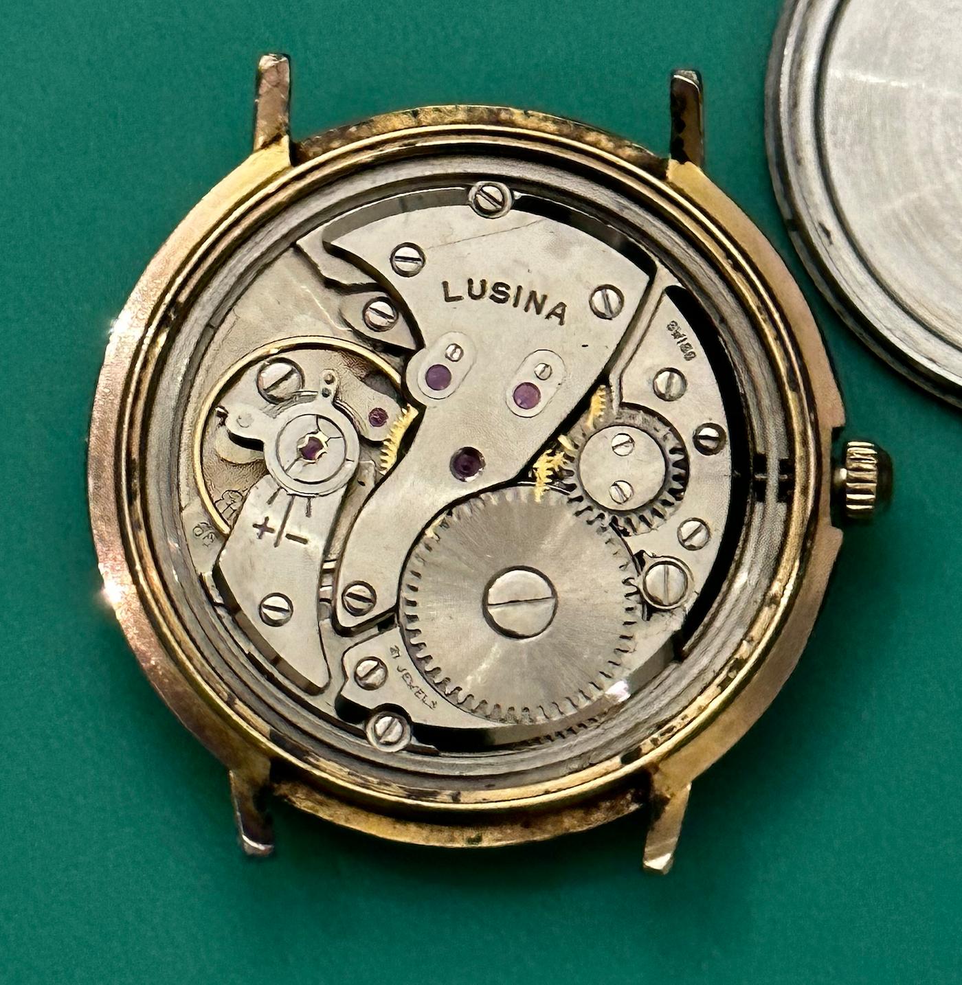
    • I decided that it was time to tackle the piece that I'd set aside as my first project. The subject in question is a Gruen Veri-Thin pocket watch.  It winds and "runs".  On the time grapher, it has reasonable amplitude (240 or so depending on the position), but was loosing close to a minute a day.  The stem also has the annoying tendency to just come out when pulled, which makes it super hard to set the thing.  As with many things this one started sideways and just got more so.  I was able to overcome the mangled "tab" on the back case cover (a well placed, very sharp knife enabled me to get in when I couldn't get a purchase on the mangled tab with a case knife.)   I was then sort of shocked to find that one side of the dial was held down with some sort off tape or adhesive material as someone had broken the dial foot screw on that side and left the broken screw in the mail plate. The loose stem does in fact seem to have been a poorly tightened setting lever screw, but I'm afraid there may still be gremlins in the keyless works.  While I was able to get the stem to stay in by putting everything in the right place and tightening the setting lever screw (before I took it all apart for cleaning and inspection), it just didn't seem to all sit right. The final gremlin showed up when I was taking off the lower cap stones for the balance and escape wheel (yes the Gruen 380 seems to have a cape jewel on the escape wheel).  The balance stone came off fine (but that in fact is the smallest screw I've ever seen.  When I turned the movement around to get the one off the escape wheel setting, I found that the screw head had been mostly sheared off.  After some reading and looking at what I had, I decided to try and tease what was left of the screw out of the hole by nudging what was left with the corner of my smallest screwdriver.  After 20 minutes or so, I was able to get the remains of that screw out. The picture I'm including of the disassembled movement was taken before I got the second cap stone off, so in the picture, it's still attached to the main plate (for those looking carefully, you'll only see the one cap setting in the pic.) Now I'm left with: A broken dial screw inside the main plate that needs to come out A broken cap stone retention screw that I have in my parts tray, but that is strictly useless and needs to be replaced. The need to get another dial foot screw I'm contemplating solving the first problem by soaking the main plate in an alum solution.  I think the main plate is brass and shouldn't be affected, but I have not been able to confirm.  This seems like the easiest option as I can't really access both sides of the screw to use the pricey Bergeon tool (which I don't fancy buying unless I have to.) I have located a couple of donor movements and have questions out about whether or not the include the dial foot screw and prompting for pictures of the dial side so  evaluate the cap stone settings.  I've also found that a supplier in this country does have the cap stone settings, but isn't overly clear about whether the screws are included. Are these the types of things that one can scavenge out of assortments or is it best to just grab one of the donors assuming that they look like they have what I need?  
    • I visited this place last year just before they closed their counter service - amazing shop (filled from floor to ceiling!) and the guy that was working there was really knowledgeable and helpful!. Their website isn't as good as Cousins but I understand that if you fill out the contact form they have stuff that isn't on the site. https://gleave.london/mineral-flat-bottom-domed/
    • As always in this game the answer is “it depends “ because the first one worked out ok doesn’t mean all will. A case could be made in a way that it would not really matter much, sounds like your first example. However a case could also be made so that only a tension armoured crystal could be used. Generally you replace like for like to maintain the integrity of the watch.   Tom
    • When can you use a standard crystal to replace one that had a tension ring? The first time I popped a crystal with a tension ring out of a watch I found that I had a suitable sized standard crystal and decided to try that.  It fit nicely and it was hard to see that anything was missing from the watch.  I understand that it probably reduced the water resistance of the watch but since it was an old dress watch it wasn't going for a swim anyway! I have since tried the same thing on another watch and found that the tension ring seemed to have an additional role of holding the dial in place.  With the standard crystal in there the dial and movement falls forward. This means it rattles in the case and falls forward and the hands fowl on the crystal (when the dial is down). Is there a trick I am missing here or does this watch require a special crystal?  I am reluctant to buy an expensive armoured crystal only to find I have the same problem.  
    • So I wrapped the anvil it in bubble wrap and passed ot through the demag only. Still no go—the unit is simply too strong.  next experiment is to use a VARIAC to lower the voltage and see if that reduces the magnetic field. 
×
×
  • Create New...