Jump to content

Help replacing chronograph pusher tubes


Chopin

Recommended Posts

Can someone tell me if these tubes are replaceable or not ? While trying to remove one I managed to damage it badly. The thing that makes me think that they are not part of the case is the fact that they both sit at different heights inside the case. Are these screw in ?

Trying to unscrew the damaged one but it doesn't seem to move.

The reason I wanted to remove them is stupidity and the fact that it's missing a pusher so for some reason I thought that it was appropriate to try and remove the tubes. I've done a  booboo, I know.

20191225_170611.thumb.jpg.39bd21e155fa2f6973cb2e5f11a7da73.jpg

20191225_170546.thumb.jpg.aa9fe76e8282f5a22f6ac20ffdef20d6.jpg

Link to comment
Share on other sites

6 minutes ago, Chopin said:

I won't be attempting to remove the other, the problem is that the one that I tried removing is now really damaged and needs to be screwed out.

Any tips ?

Unless there is damage to the inner side or how the pusher works, leave it alone.

  • Like 1
Link to comment
Share on other sites

21 minutes ago, Chopin said:

The damage is bad. It has to be replaced. I have to get it out. :(

You can use a screw extractor. Search Internet to see what is that. Heat well the case around the tube before and proceed carefully. 

Edited by jdm
  • Like 1
Link to comment
Share on other sites

Equivalent tool for a much more reasonable price.
https://www.aliexpress.com/item/4000298591084.html
Lol. I was trying to be all watch maker uppity....the one you shared is actually the one I have. Ive learned that for every ridiculously overpriced watch tool there is a cheap chinese knock off. The trick is knowing when the knock off is decent enough. Some times the chinese knock offs arent worth the cost to ship them.


Sent from my SM-G950U using Tapatalk

  • Like 2
Link to comment
Share on other sites

Alright, I managed to extract what was left of the tube.

Guess what ? It was a freaking push in tube, not screw in.

I thought that those that have those little threads/spikes on the edges are supposed to be screw in... Oh well, another lesson learned. Thanks guys! Panic mode off. :)

I had tried pushing it out but couldn't so assumed that it's screw in.

Edited by Chopin
Link to comment
Share on other sites

Out of curiosity, is it possible to extract these push in (or should I say drive in) tubes without one of those expensive tools ?

Once I was able to install the tubes by using a crystal press (and improvising a bit) but don't know I could go ahead and remove the remaining one. The reason I'd like to remove it is to measure it so that I'll know what replacements to order... Do I even need to know the dimensions of that tube ?

Link to comment
Share on other sites

20 hours ago, jdm said:

You can use a screw extractor. Search Internet to see what is that. Heat well the case around the tube before and proceed carefully. 

    there are 2 types of  screw extractors available.  the square and the spyroll.   i like the square.    vin

Link to comment
Share on other sites

17 minutes ago, bjd1020 said:

    is there a "tool maker"  in the house?      vin
SEND ME YOUR SKETCHES

I HAVE CNC CAPABILITIES

Sent from my SM-G950U using Tapatalk
 

  they are listed in any tool catalog  - you can make the square ones out of "key stock".  vin

Link to comment
Share on other sites

Managed to remove both of them and they got damaged in the process but one pusher was missing so I'll get a new pair anyway. The thing is that I've looked a bit on CousinsUK and so far those on the website don't exactly seem to fit my required dimensions.

For example all pusher diameters are in increments of .50mm. Mine is 4,8mm I believe... Being bigger might not hurt but the hole diameter seems to be 5,2mm so I'm not sure if it'll be a safe fit. Same goes for other dimensions as well, hopefully I'll manage to pull this through.

Link to comment
Share on other sites


  • Recently Browsing

    • No registered users viewing this page.
  • Topics

  • Posts

    • Could you print the image either enlarged or reduce the the same size as the actual part and then glue it to the steel. 
    • Next is to drill the screwhole this then provides an anchor point so the bridge doesnt slip around while scribing the shape. A cork lid, a pin and a piece of gaffer tape ( 😅 ) keeps it all in place. The hole is measured from the broken part using a hand measuring gauge. Mark the hole, punch it and drill it off to size. The awkward bit is working out where the jumper should be and the detent positions.  I remember watching a youtuber a while back do this with dividers, so i dug out my old school compasses and improvised a little. This bridge only has one hole and to find the detent positions you need two points of reference, so i just worked the second point from one of the corners, hopefully its near enough. Then scribe in the jumper using the two detent positions ( wind and time set ) that were marked and a big picture of the complete spring to look at that helps to give you a feel of where the jumper should be.   
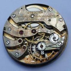
    • Right now I'm making do with a similar micrometer (the one below is $45 shipped but you can find better deals) and a $20 stand. You do have to be excruciatingly careful measuring jewels, since there's no table, but if you don't have the $500 to throw around, it's a nice option.
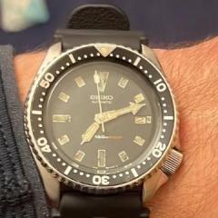
    • As  I kid, I'd watch Godzilla stomping over buildings and cars and I'd think to myself: Tokyo is a really dangerous place to live... . Cool watch!!
    • Next one up an AS 554, looks like a bit more to this one. First job is to check thickness, most springs are somewhere between .3 and .4, this one measures .35, that matches in with the .4 spring steel i ordered. So for marking up a permanent marker comes in handy to colour up the steel to be marked later with a scriber once its dry. Bestfit provide the extra bit of info for the jumper spring that is missing.
×
×
  • Create New...