Leaderboard


Popular Content
Showing content with the highest reputation on 08/17/18 in all areas
-
Can I suggest you practice on some scrap steel first before trying it on a watch case, much better to make the learning mistakes on some scrap than something valuable. I've not ever tried to refinish a case so will be interested to see your results1 point
-
Here is a link to P/W parts photos these came from IHC185 club by John D. Duvall https://www.dropbox.com/sh/27ej5vl7etzaqzi/AADuOsY6QNnl8heHIweN3OcGa?dl=01 point
-
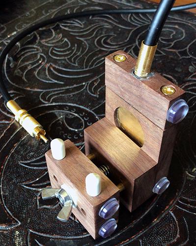
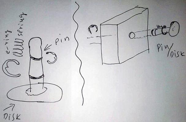
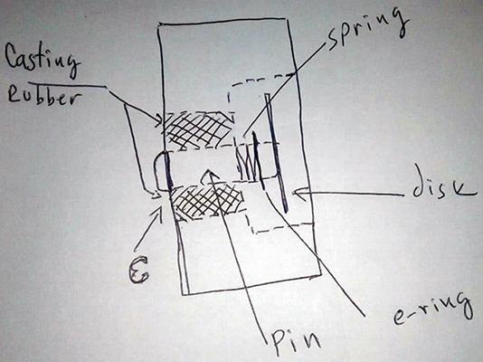
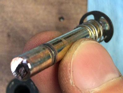
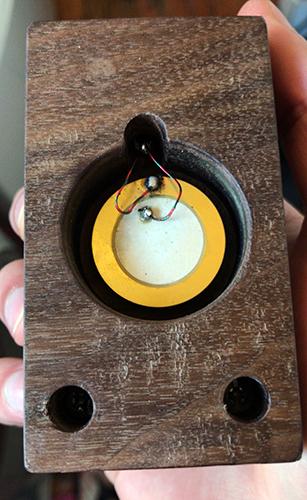
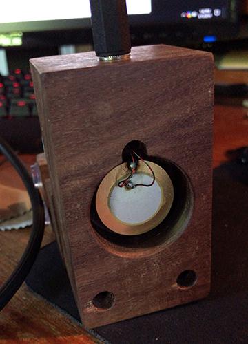
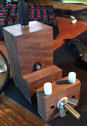
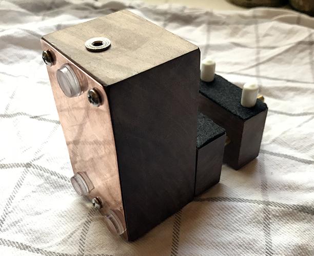
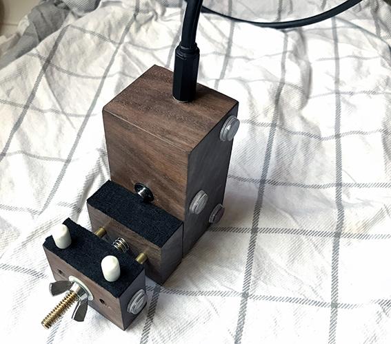
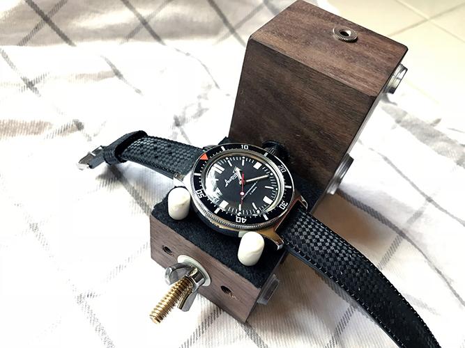
I've already posted this on another popular watch forum, but I think it better fits here. I'm sorry if this post get too lengthy due to all the images. Hey everyone! I would like to share a project that I've been working on for a while. After a few different variations, I think that this is my final design for the time being. Project background: For many in this hobby, applications like Toolwatch are great because they allow you to determine daily rate, but it doesn't provide anything beyond that. Those of us who enjoy tinkering with watches should have a way to also check the amplitude and beat error. Sure, I could have purchased a timegrapher from China but I thought it would be a fun project to attempt constructing one myself (with the help of several resources). I used these microphone stand plans for reference and made some changes. There are also plans for a DIY pre-amp on the Watch-O-Scope website, but I followed the instructions from my good friend Guido (also posting on this thread) and modified a PYLE pre-amp by removing a capacitor from one channel and replacing the electrolytic capacitor with a ceramic capacitor on the same channel. The first iteration gave promising results but I wasn't entirely pleased with it. It seemed like the audio levels were somewhat inconsistent and I would get a ringing or echoing noise depending on the amount of pressure against the piezo disk (the contact microphone element). After some discussion with a friend, we came to the conclusion that many professional timing stands never have direct pressure against the piezo element - instead, the metal clamp that holds the watch is coupled with the piezo using a different piece of metal that transfers the vibrations. We came up with these sketches for a better design. Completed and polished pin before attaching it to the piezo. Pin installed. Soldered some thin cables from broken earbuds to a 3.5mm connector mounted in the stand. The results are good. Now it's time to add a copper plate to the back to reduce electromagnetic interference. Another good idea is to add some felt so I don't scratch any crystals when testing the dial down position. Finally, the build is complete! I'll admit that this might not be the most beautiful creation, but it's definitely functional and it does exactly what I need it to do. I have ideas for further improvements, but they are not necessary and are really just a challenge to get the cleanest audio signal (there's still quite a bit of static). Waveform from Watch-O-Scope (highly recommended software, made by a fellow WUS user). This is amazing software that I pair this microphone stand with. An alternative is TG Timer, but Watch-O-Scope definitely is the better option. Quick audio recording I made: Test Recording #1 - Mega.nz
 1 point
 -
This guy always seems to have loads https://www.ebay.co.uk/sch/ramps333/m.html?_nkw=&_armrs=1&_ipg=&_from=1 point
-
Hi Fred, Welcome and yes, we all find the old mech watches very interesting. I fix them mainly but spares are a real problem at times. Quartz are OK with me as well . I have little in the way of likes and dislikes with timepieces. I do not collect! All good wishes to you. Regards, Mike.1 point
-
Welcome to this friendly forum.1 point
-
Try here; http://www.timezonewatchschool.com/WatchSchool/Glossary/glossary.shtml or for a downloadable .pdf version; http://people.timezone.com/mdisher/WatchSchool/pdfs/TZIllustratedGlossary.pdf1 point
-
Welcome Fred, Enjoy the forum.1 point
-
For those who have not serviced /repaired a 400 day clock I thought I would show (by vids) how absolutely everything must be correct for a successful outcome. The first vid is after cleaning and re-assembly using the original suspension spring. At first all looks OK but It was running slow and I just run out of adjustment. When I measured the original spring it’s thickness was 0.0019” the correct thickness (using my 400 day ref: book) should be 0.0023”. When the new spring was fitted it ran with a better rotation but it then suffered with what is called “flutter” This is where the escape runs away uncontrollably for a brief period. To remedy this the folk that operates the escape was moved up the suspension spring a fraction.Also there was a slight wobble when the pendulum rotated this was traced to the lower suspension block not being absolutely centred and on the skew ( very marginally) if anything now it has to much rotation but it is keeping excellent time. Before correct spring fitted IMG_2575 (1).mov After the correct spring is fitted (with tweeks) Vid 11.mov1 point

.jpg.6225a64433578a11e0218b27c20b13f5.thumb.jpg.d82b0cd1e370f3a3a59a06afa957d184.jpg)