Leaderboard


Popular Content
Showing content with the highest reputation on 07/10/17 in Posts
-
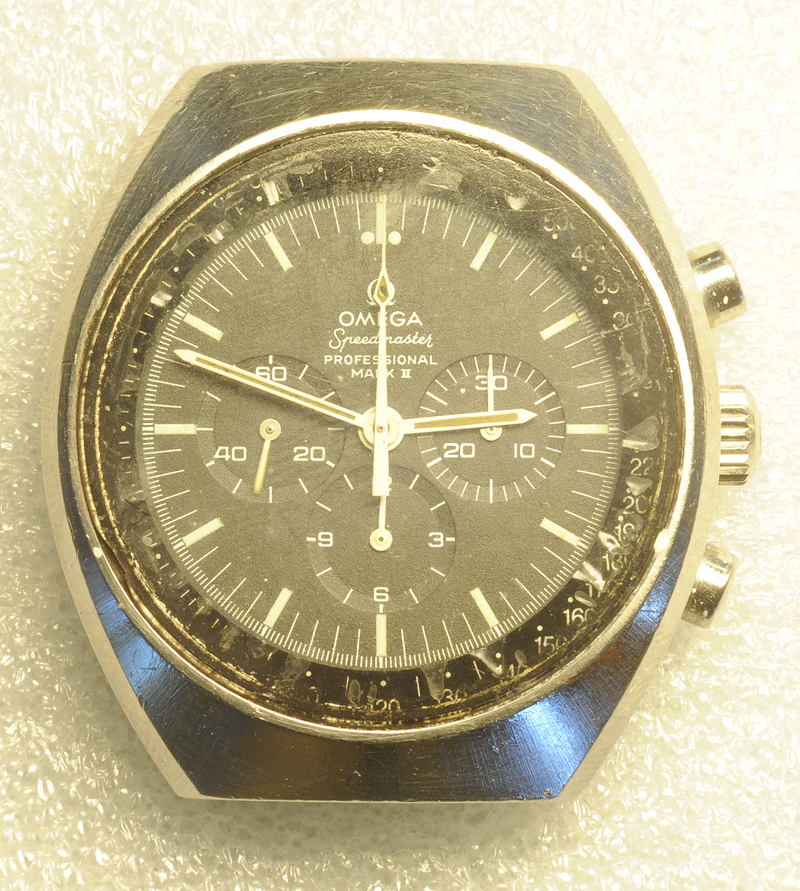
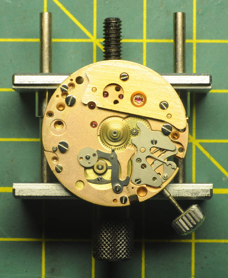
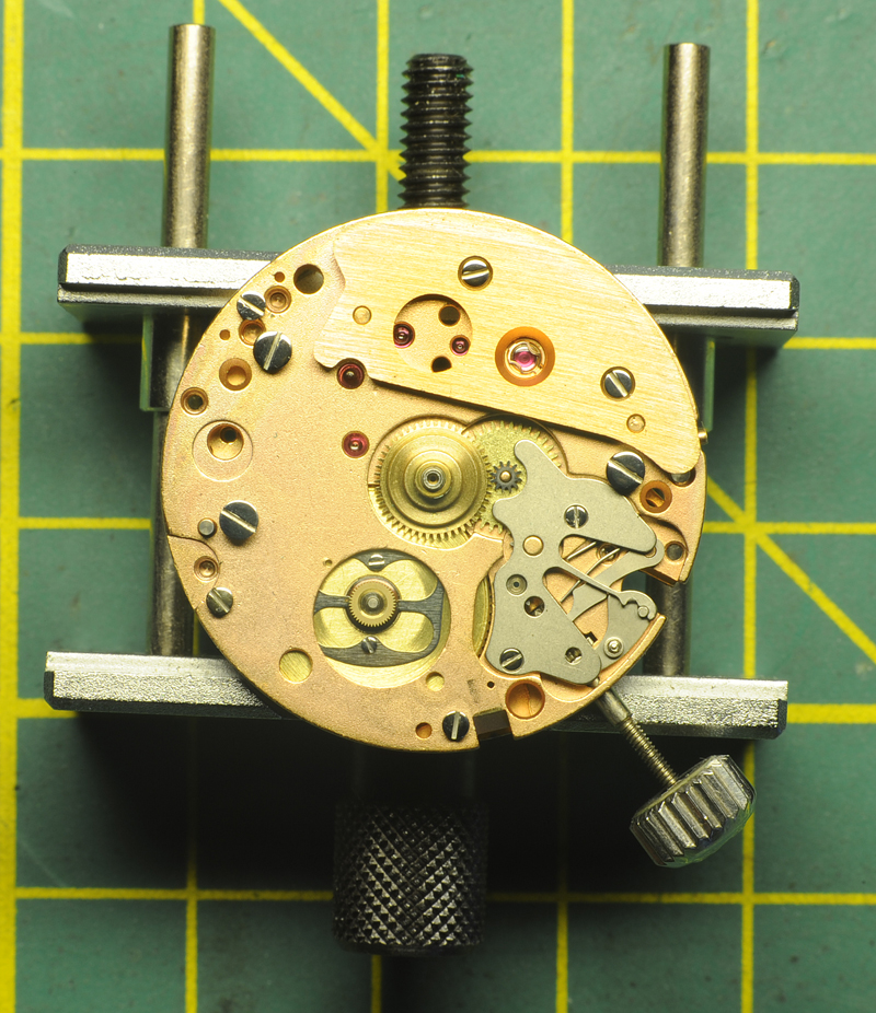
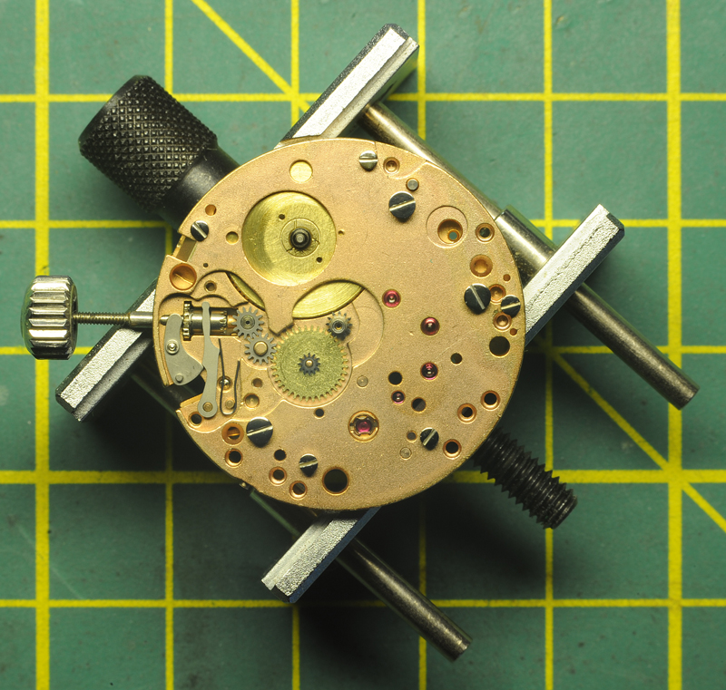
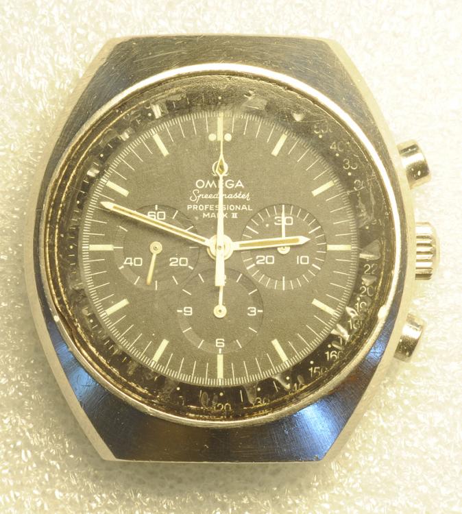
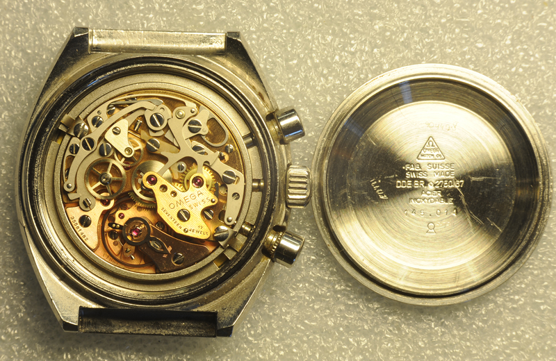
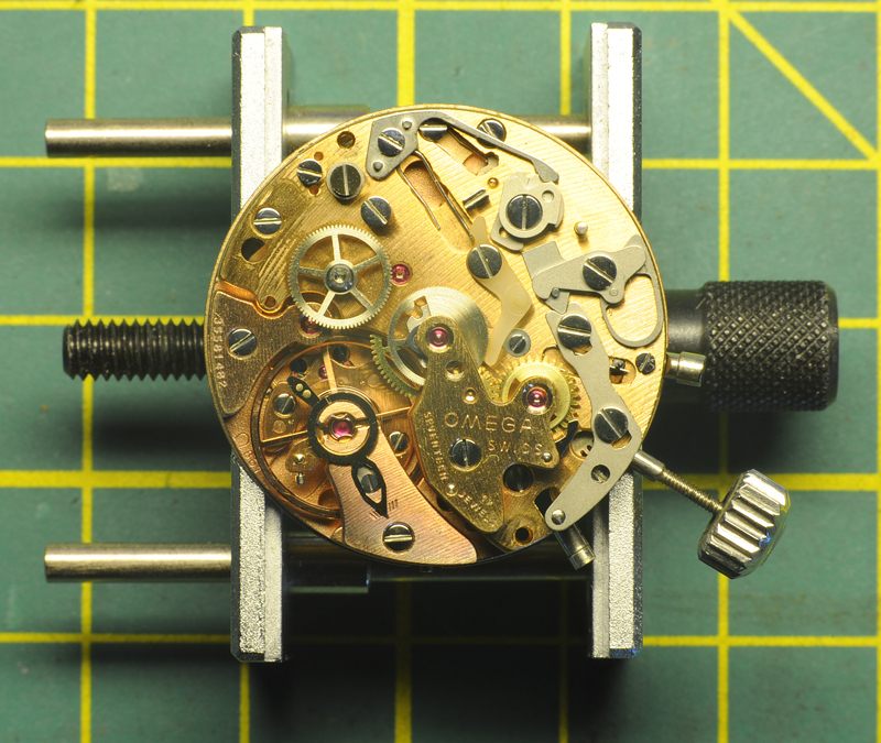
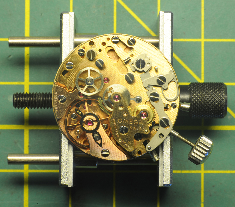
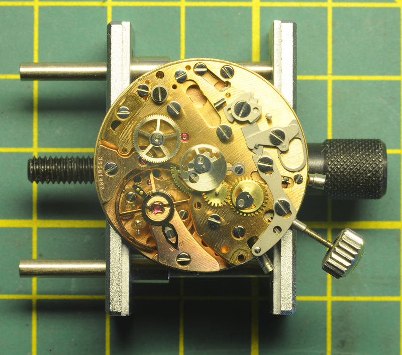
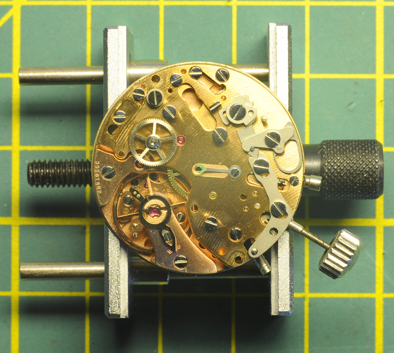
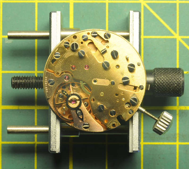
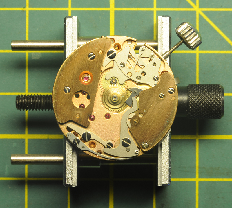
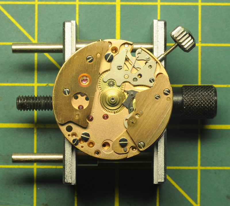
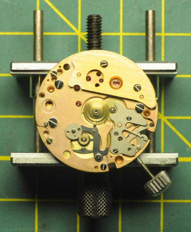
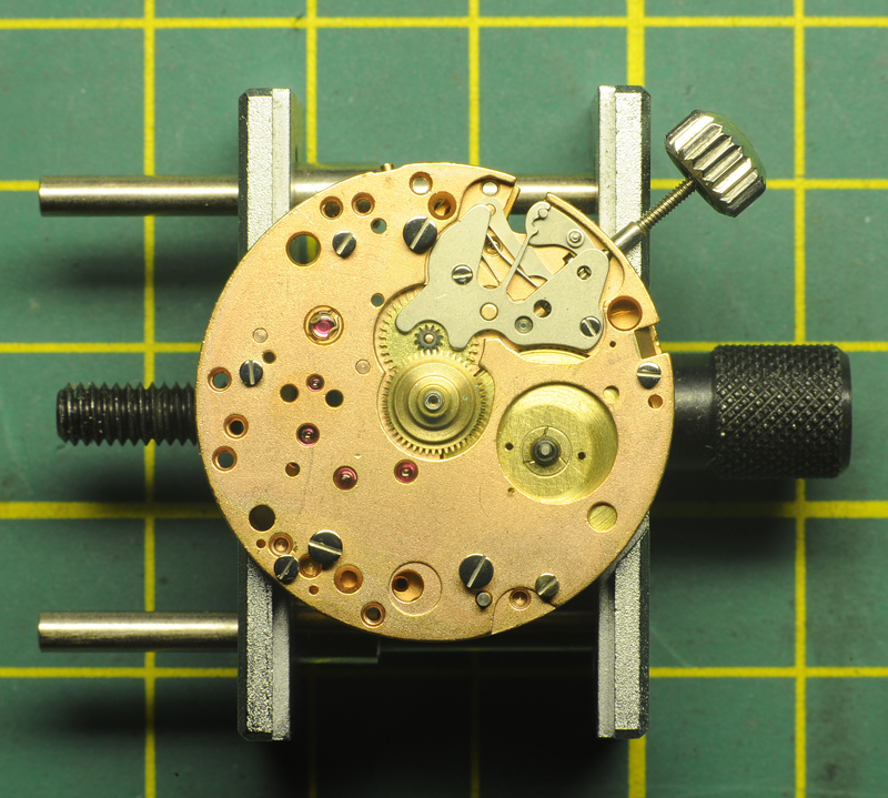
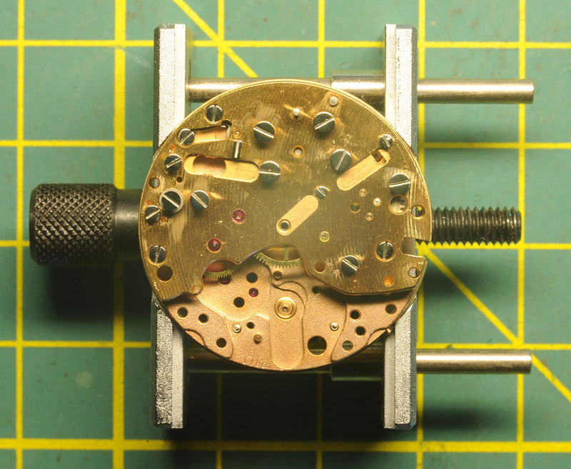
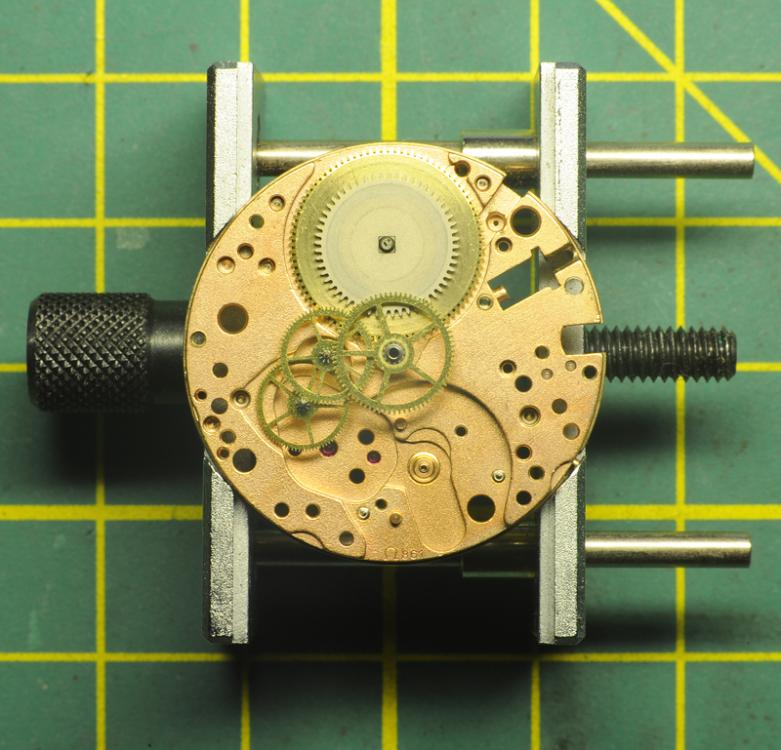
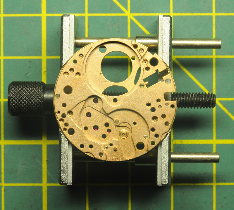
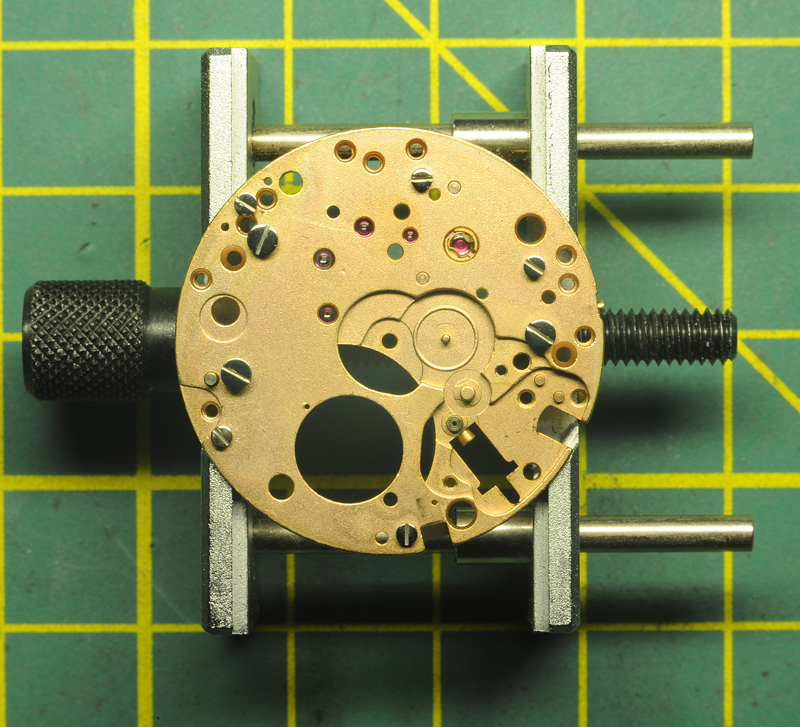
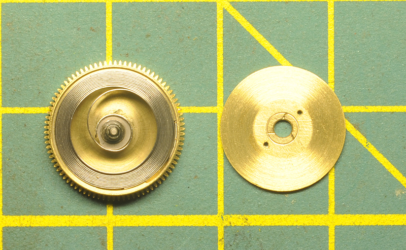
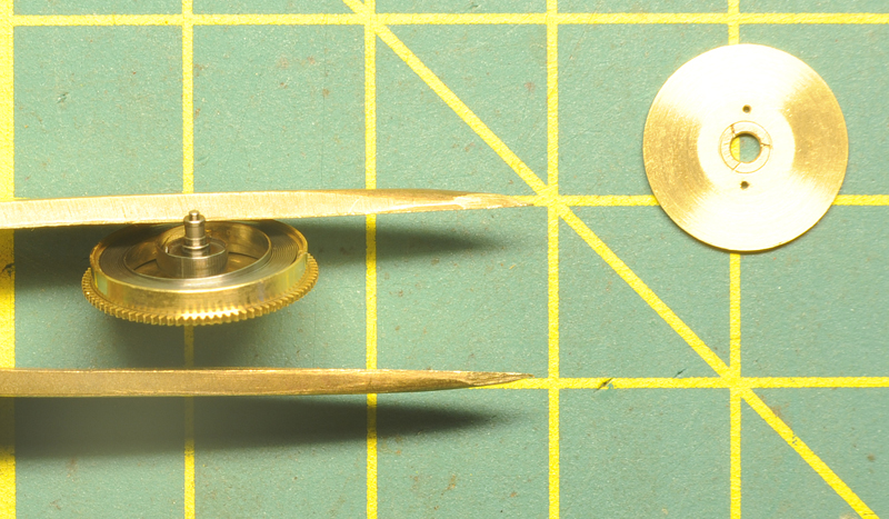
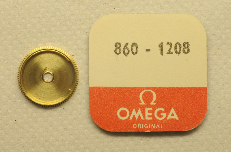
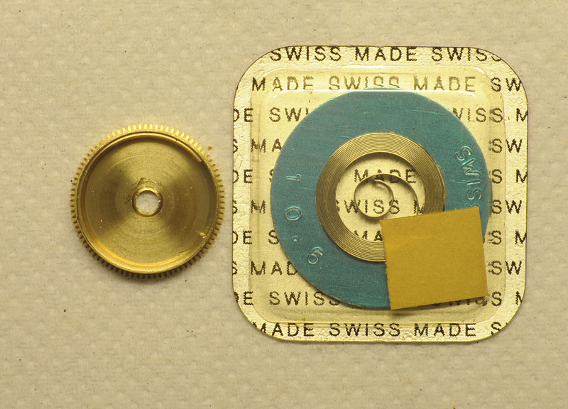
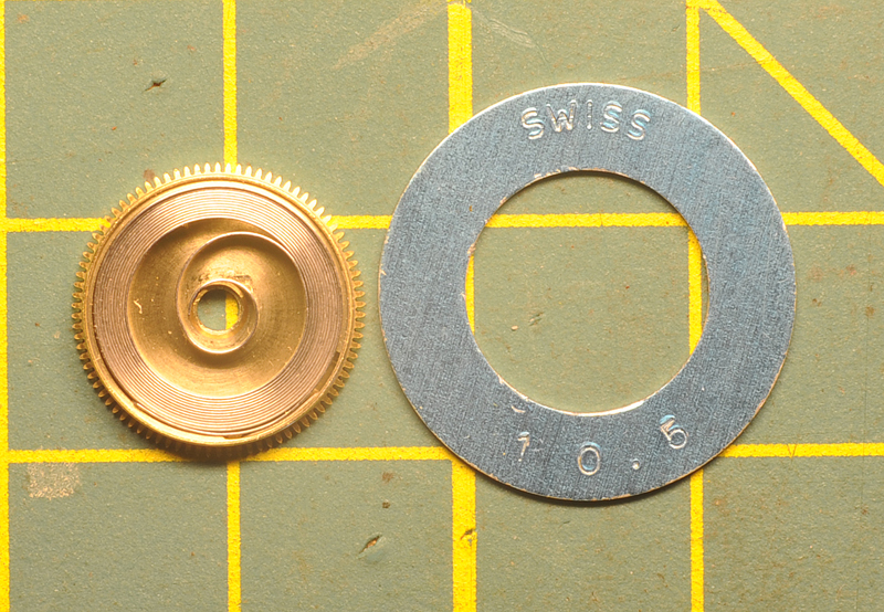
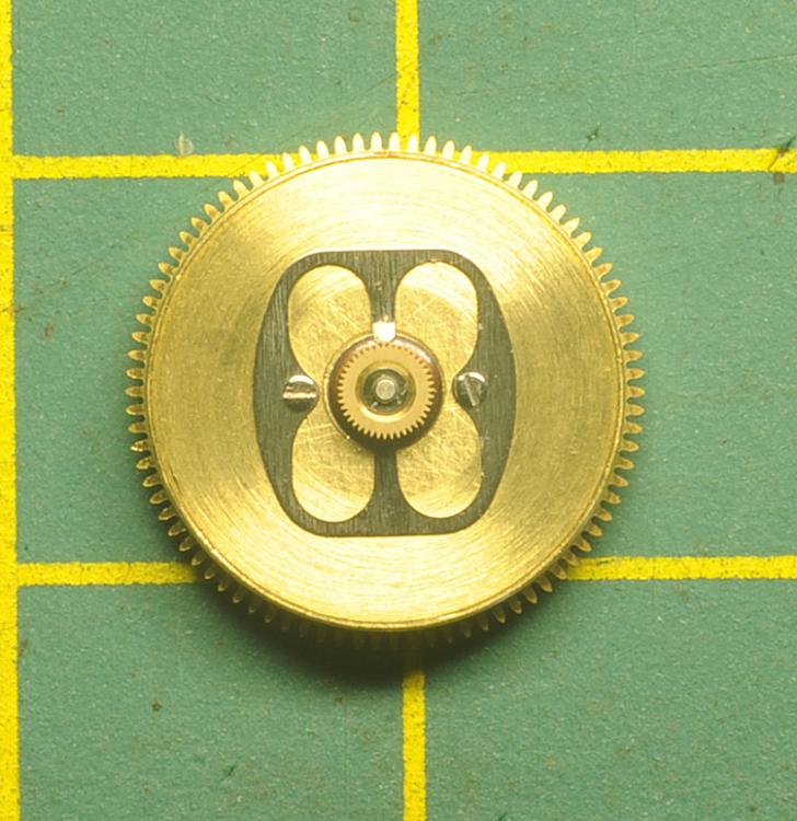
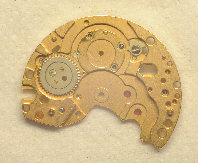
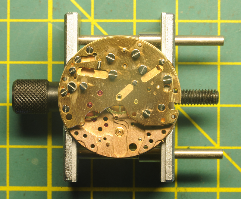
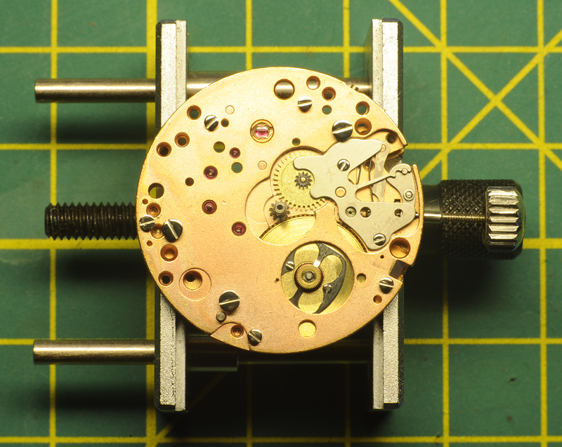
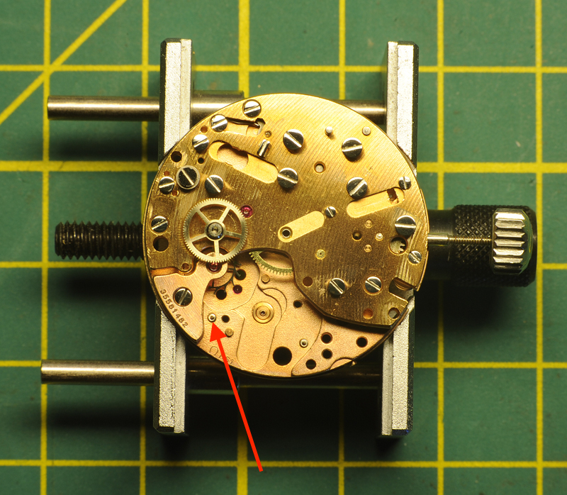
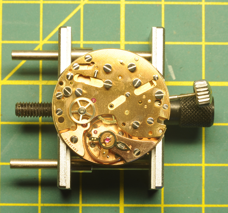
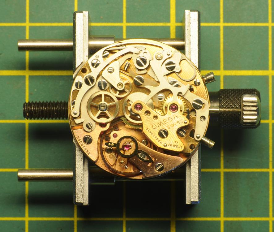
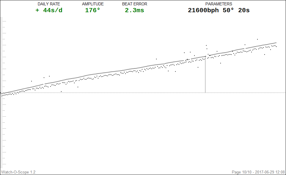
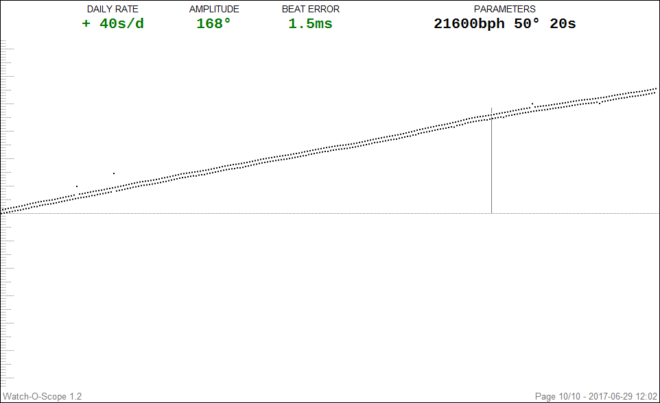
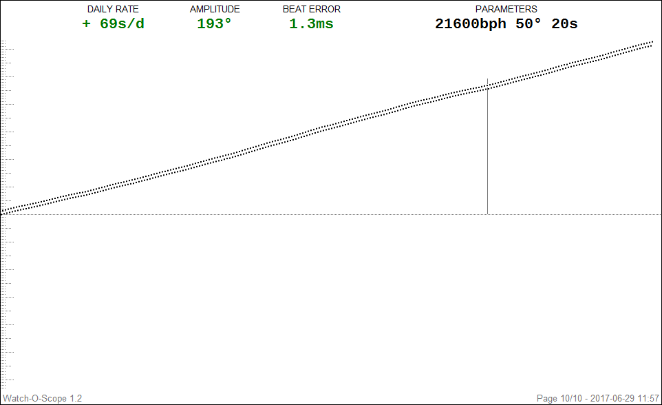
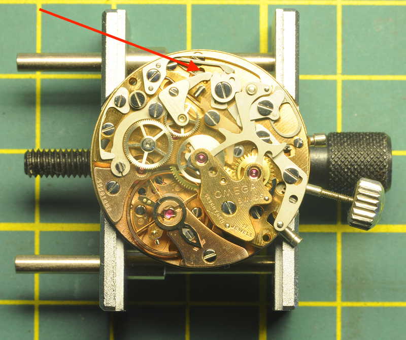
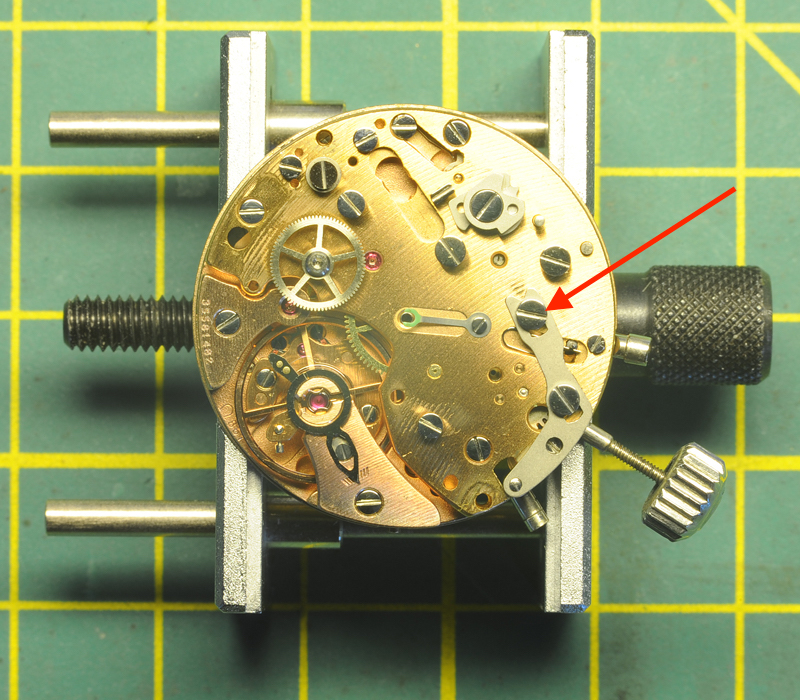
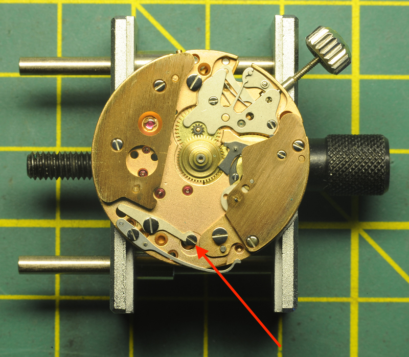
Hello All; On my desk landed a 1975 Omega Speedmaster professional Mark II. It was in a sorry state and water ingress was suspected. The last services were quite a few years ago, mid '80's towards the '90's. Those services were performed by a watchmaker working for a local highly reputable jeweler with a glossy facade. Instead of using the proper tools (a guide-ring) to replace the glass, for ease or necessity the official seal-ring was taken out and the glass was placed using a black sealing-kit. The back-cover received the same treatment, instead of the correct O-ring, the O-ring groove was filled with the same black sealing kit and the cover was thereafter closed. By a stroke of luck, the Omega was replaced by another watch and has for 20+ years been stored in a drawer; until recently. The owners current watch was sent away for a service and the Omega had to fill the gap. Unfortunately the Omega came in contact with water. The owner suspected water ingress and as soon as his current watch was back from servicing, the Omega was sent to me. Though time, the black sealing kit has eaten away the printed Tachograph-ring and made its way onto the edge of the dial. The task on hand; a full service of the movement, installation of a new mineral glass and replacing all seals. Perhaps some new luster to the watch-case........ Whether I show the full restoration of the watch-case needs to be seen, but I like to start off with a walk-through of the 861 movement. Two Omega 861 manuals were of enormous help; Omega 861 service manual.pdf Omega 861.pdf I printed them out and best is to read and cross reference both manuals before starting. Each manual contains important information, not necessarily mentioned in the other manual ! Once the information is combined, then there is enough information to do a proper service. For chronographs like this one, I replace each screw after the component has been removed. This avoids screw mix-ups, but can cause some problems too ...... read installing the pallet-fork bridge. Without any further ado; Here is the watch as I received it; Luckily the inside looked pretty okay and no visual signs of water. BTW, the black sealing kit on the back was already replace by a proper O-ring. Took some Watch-O-Scope shots (lift angle 50 degrees) Dial up: Dial down; Crown Up; Crown down, this one was harder to get due to a weak signal; All in all, not too bad.......... at least not "devastating" differences in the four positions. The movement is attached to the case with two clamps and a spacer ring. Remove those plus the winding stem and the movement can be taken out. Clearly visible is the black sealing-kit around the dial edges, starting from 5 till 10-o-clock. Pay special attention when removing the little hands, these have different tube sizes. I stored them separately, each in their own container; Left, Bottom and Right. Taking ample pictures was a great help to me as well. I had to consult them a few times during the assembly. Another remark I like to make is that the movement doesn't sit comfortable in an universal movement-holder. The movement-holder I used was a Bergeon 4040 and with great care it can be done, but later I've spotted on eBay Omega 861 movement holders for reasonable prices ..... On the picture below, the Joke 1774 has been removed. This exposes and give access to the click (see arrow). The main-spring can now be disarmed. Next is the hammer-spring 1734; it sits on two center-pins and has to be lifted at its heel. The hammer 1728 sits on a post and can be lifted straight off. Remove coupling spring 1731 and coupling yoke 1724. Be aware of the eccentric screw, it clearly has a different shape. I left the unit (wheel bridge 1716 and coupling wheel 1712) in one piece. Later I dismantled the unit and attention has to be paid which way around the coupling wheel is mounted. Removed the plastic blocking lever 1726 and blocking lever spring 1733: in the manuals different names and number are used for seemingly the same item. One end of the spring has a "hook". This "hook" has to face upwards against the blocking lever. Next to remove is the cam-jumper 1845. Next is the chronograph bridge 1037. The manuals are not very clear if one does this for the first time. Underneath and fixed to the bridge is a thin spring for the minute recording jumper. This spring will come together with the chronograph bridge. The spring pushes against the minute recording jumper 1767, which is attached to a post underneath the bridge. While lifting the chronograph bridge, the jumper 1767 may, or may not come as well. I my case, all lifted in one piece. By turning the bridge around, it all becomes clear .... Das "Aha Erlebnis" ;-) Remove chronograph runner 1705, minute recording runner 1708 and intermediate wheel for minute recording runner (1714); note which way around of the wheel ! Remove operating lever 1841, operating lever-spring 1842 and connecting lever 1840. Attention: The operating lever 1841 sits under tension. After I removed the screw and attempted to lift the lever 1841, the connecting lever 1840 had its personal launch ...... luckily not that far ...... Remove operating lever 1720. In my case, the "Glossy Facade Watchmaker" left a surprise; the top screw was sheared off right under the screw-head and screwed in by literally one thread (red arrow, picture above). I later attempted the remove the remaining stud, but no success. After consulting the owner and this being the second, more a guiding screw, the decision was taken to repeat the GFW-trick. The screw held for many years, so hopes are it will do it again. Remove (and note position) upper cam for hammer 1844, remove lower cam for coupling clutch 1843, remove stem for "Zero pusher" by undoing the screw, remove bolt-spring 1752 and bolt 1759. Carefully, use Rodeco, remove fragile friction spring for chronograph runner 1735. Carefully remove the driving wheel 1710; I managed to lift it using two hand-levers. I then removed the balance & bridge, the pallet fork-bridge & pallet and the escape wheel bridge & escape wheel. Flip the movement over; Remove bracket for operating lever 1784 (note position), remove hour hammer spring 1794 (not described in both manuals, note how it engages) and remove hour recorder stop lever 1750. Be aware: as soon as lever 1750 is lifted, spring for stop lever 1793 will jump free !! Remove spring for stop lever 1793, remove switch mounted 1779. Watch out !! Little screw at tail end is an eccentric (see arrow above) ...... do not touch !! Remove hour recorder bridge 1775; Remove hour hammer 1783, hour recorder runner 1788. Next is, according to the manual, removal of the friction spring for driving pinion 1792 and driving pinion 1791. I did this according to the manual, but found out that the removal of the friction spring 1792 and driving pinion 1791 can be done (much easier) later when the main-spring barrel is removed. Remove support bridge for dial 1776. Remove hour wheel and keyless works, note the two intermediate wheels. Remove canon-pinion. Flip movement over; Remove barrel bridge. Note crown wheel and click are underneath barrel bridge. Also note that ratchet wheel lays on top of the barrel. Remove wheel train; Open barrel and note spring position; Note arbor position; Install new spring; Install arbor, grease/oil and close barrel. Mount driving pinion for hour recorder 1791 and friction spring 1792. Grease as per manual. Service crown wheel and click. In my case the little screw of the crown wheel center was too tight and deemed not worth the risk. Applied some oil in the wheel groove. Now as for replacing the screws after each removed component; During the assembling I encountered a problem placing the pallet fork bridge and good pivot engagement of the pallet fork. After quite a few nerve-wrecking attempts, I noticed that a replaced screw on the other side of the main-plate stood proud of the main-plate and prevented the pallet bridge to seat. Once corrected, all fell in place ....... Assembling of the chronograph is the reverse of the above. Greasing / oiling is done as per attached manuals. Below; the movement is back together, running and all functions work ..... Tomorrow adjustment of the daily rate & bear error. As said, I may or may not follow up on the case restoration. Cleaning the dial is another challenge ....... Hope this walk through is to somebody of any use ....... ;-) Roland.


 2 points
 -
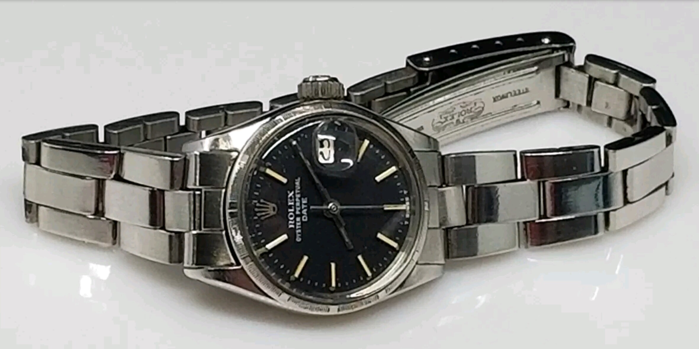
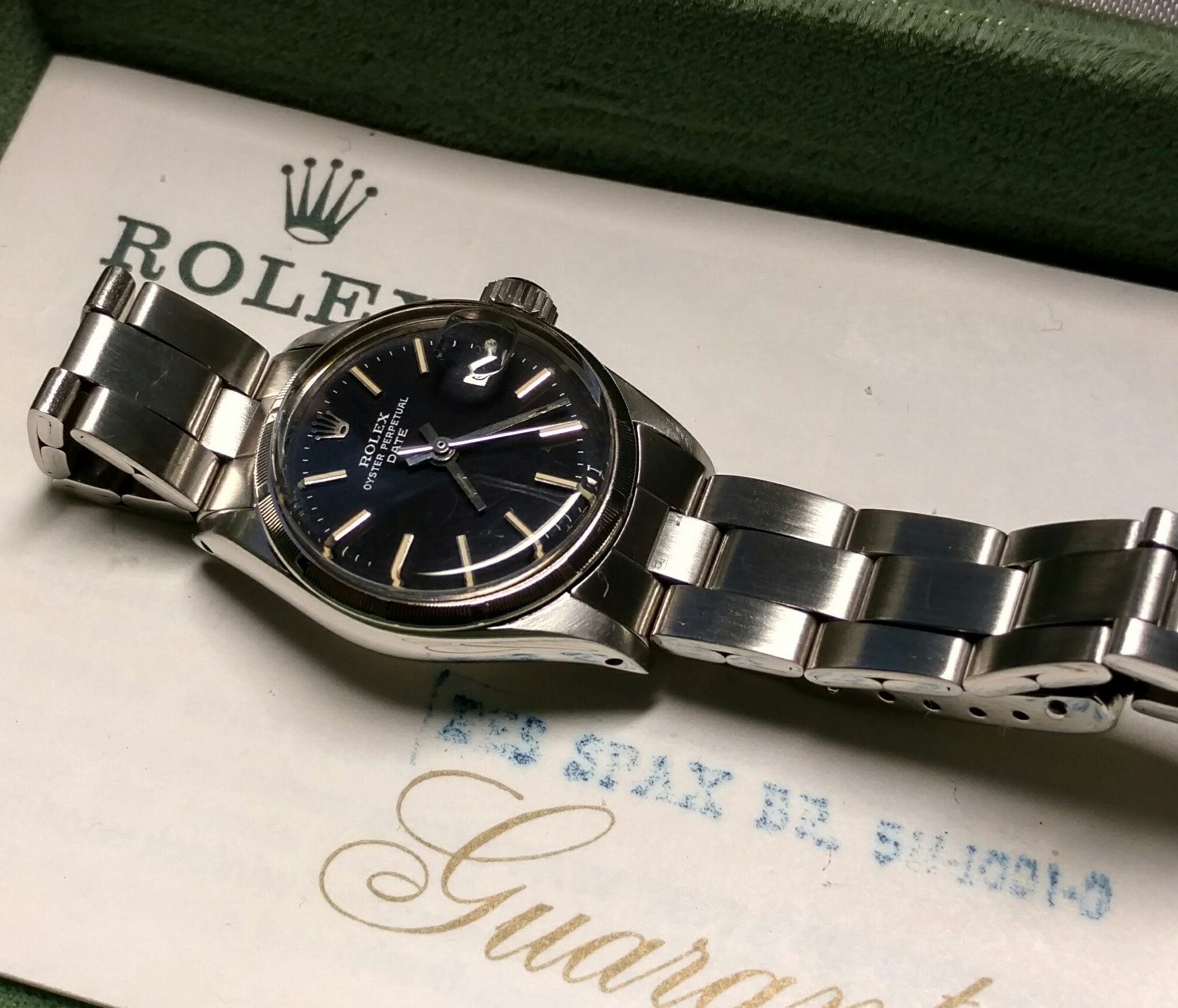
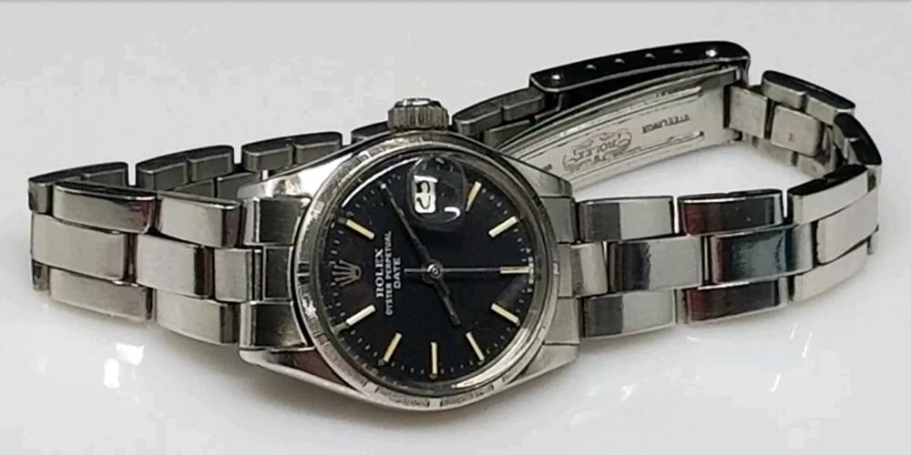
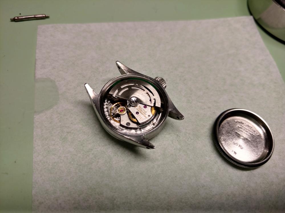
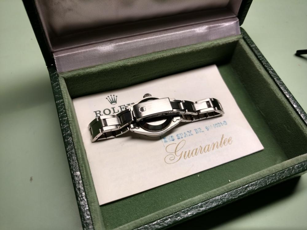
I got a great deal on this woman's Rolex model 6519. Nobody bid on the very low starting price of $599. That made me kind of nervous when I won it with the only bid...I'm thinking what do I see in auction pictures that everyone else sees and prevented them from bidding on it... Luckily, when it arrived it was was in better condition than the auction pics..I posted a pic of it from the auction... It was polished by someone who didn't know that it should have a brushed finish. (First picture) all other pics are during disassembly, reassembly and after refinishing the case.. Also came with original box and warranty paperwork...from 1971!


 2 points
 -
Still waiting for other Italian suppliers to get back to me but I just remembered I got some spare links from Toshi of KKHServices in Guilford. Give him a try, very helpful guy. http://www.kkhservices.co.uk/contact-us/ Sent from my Honor 5c2 points
-
Depending on where the shim is, it could be either to reduce or increase end-shake. If the shim is outboard of the screw, it will tilt the balance cock inwards and thereby reducing the effective distances between jewels. If the shim is inboard of the screw, The tilt will be upwards = increasing distance between jewels. This way is not ideal as the jewel holes will not be inline and the pivot will sit an an angle. One possible scenario is if the pivot had mushroomed. It would be possible to remove the trace of the 'mushrooming' but this will leave the pivot slightly short. Shimming may be a way to reduce the resulting endshake. Any hack is to reverse the cap jewels as this gives a very slight reduction to the endshake. Anilv2 points
-
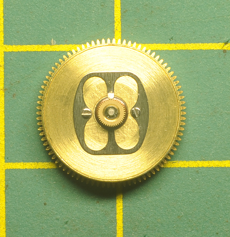
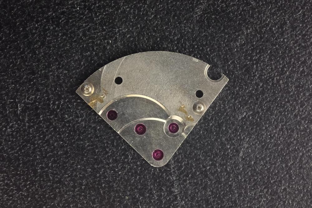
Just wanted to show something odd that I ran across, and see if anyone might have an idea of why someone would do this. When I opened up this watch, I found that a previous repairer had shimmed the train bridge with paper at the OD. After further disassembly, I saw that there were also dimples on the other side of the bridge, I'm presuming they were put there to increase end shake. At this point, though, they are worn down enough that they can't be doing very much. So a bit puzzled, I proceeded to clean and re-assemble the movement, without the shims or renewing the dimples. The train bridge was a bit tricky to get in place, being more of a cock than a bridge, but once I had everything lined up and tightened down the wheels all moved freely, and as best I could tell end shake was good. So, the question is, what was all that hacking of the bridge about? An attempt to make it easier to get the bridge lined up? Inquiring minds want to know!
 1 point
 -
I would buy a 1 mm mineral crystal with I gasket maybe 33,7 or 33,8 . As it comes with the gasket also. If you go with the old gasket? which is not really recommended? I would try 33,1 and 33,2 . It's difficult to say and you could maybe end up trying a few different sizes before you get the right one? https://www.cousinsuk.com/product/100mm-with-igasket-sternkreuz-msi1 point
-
SwissForniture.it replied Don't stock it [emoji20] Still waiting on another to get back to me. Sent from my Honor 5c1 point
-
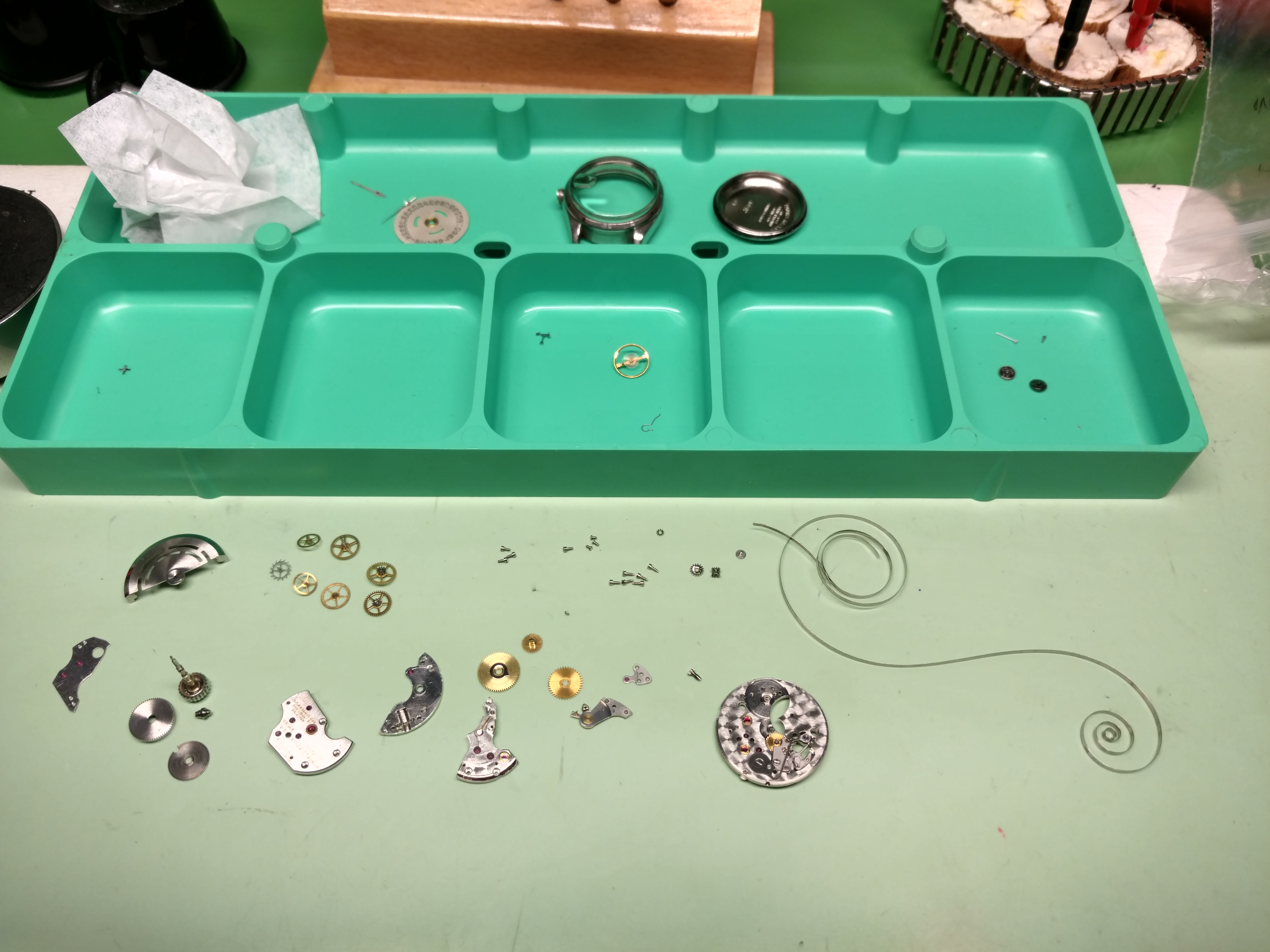
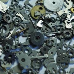
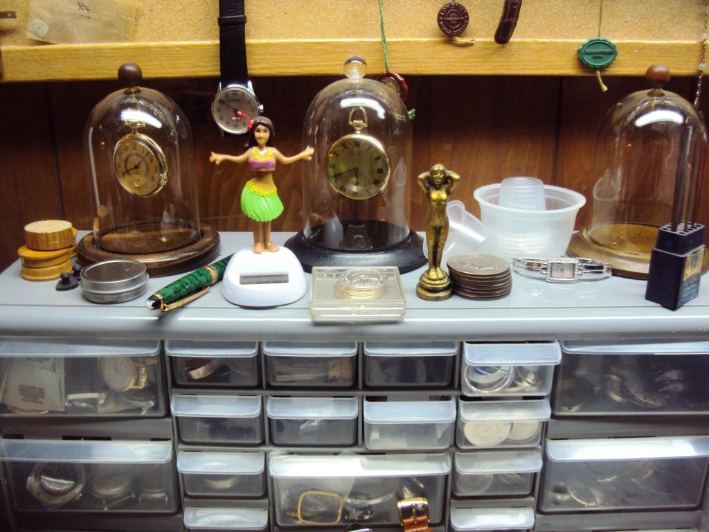
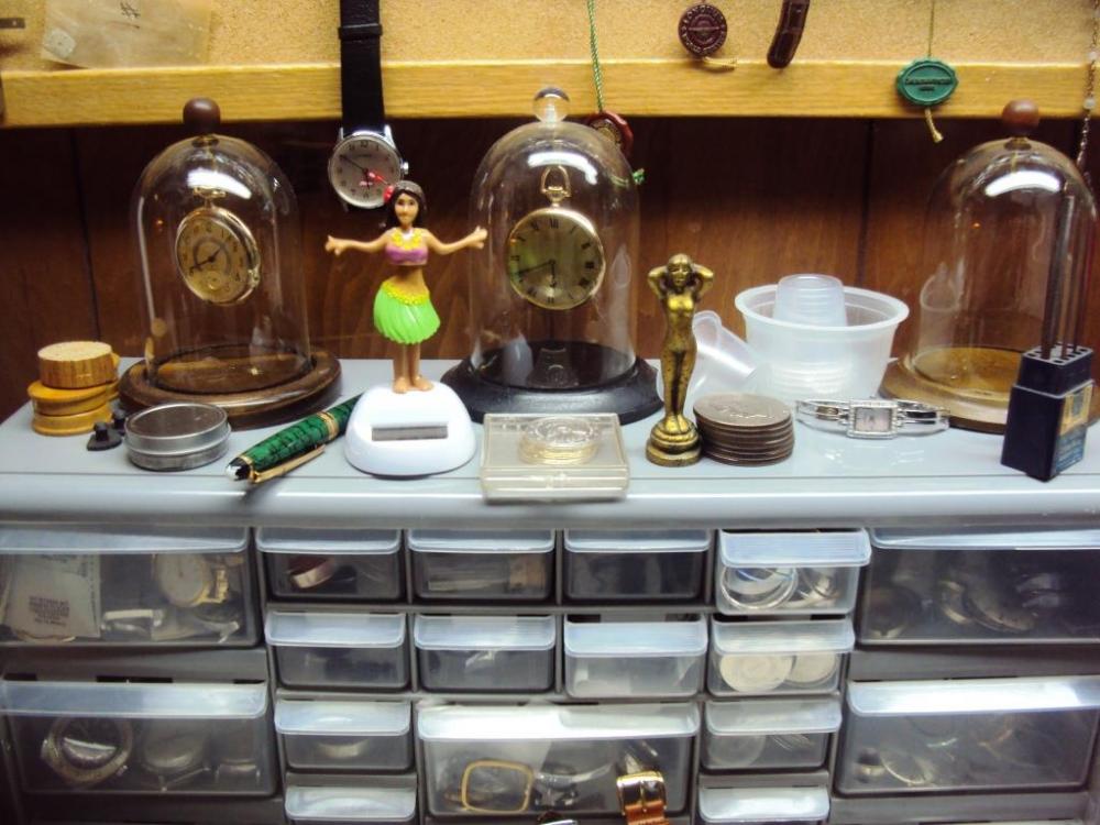
I started on the kitchen table, went to the computer desk, next to mud room on a folding table and now half of the storage room. A combination of office storage, leftovers and what ever else I come across. This is typically how it looks, organized chaos when I get into mode for eBay sales. About once a month I tidy it all up and say yes this is how it is going to stay. But, than I get in a fresh lot and it starts all over again. The solar hula dancer is how I checking the timing....j/k
 1 point
 -
Aren't they part of the same group that also owns Goldsmiths ? [emoji4] Sent from my Honor 5c1 point
-
well, at least someone knows what it is. vin1 point
-
You may be able to buy the part, but will need the part number. Starting point is the complete reference number. This will be on the case back. The first 4 digits are the movement number then you get the case number. Sometimes you will get lucky and find that Boley, Jules Borel or Cousins lists the parts for that case. For example http://boley.de/en/case-parts/citizen/15756?l=7&q=Q01661, although in this case only one pusher type is listed. Once you have the part number you then need to try Jules Borel, Cousins, Esslinger, eBay, etc to see if you can find one. You may find someone on the Seiko and Citizen Watch Forum who can look this up in a catalogue if you are still struggling.1 point
-
You might find another model Citizen of the same era uses the same part and is less than 150 gbp! Cheers Neil Sent from my iPhone using Tapatalk1 point
-
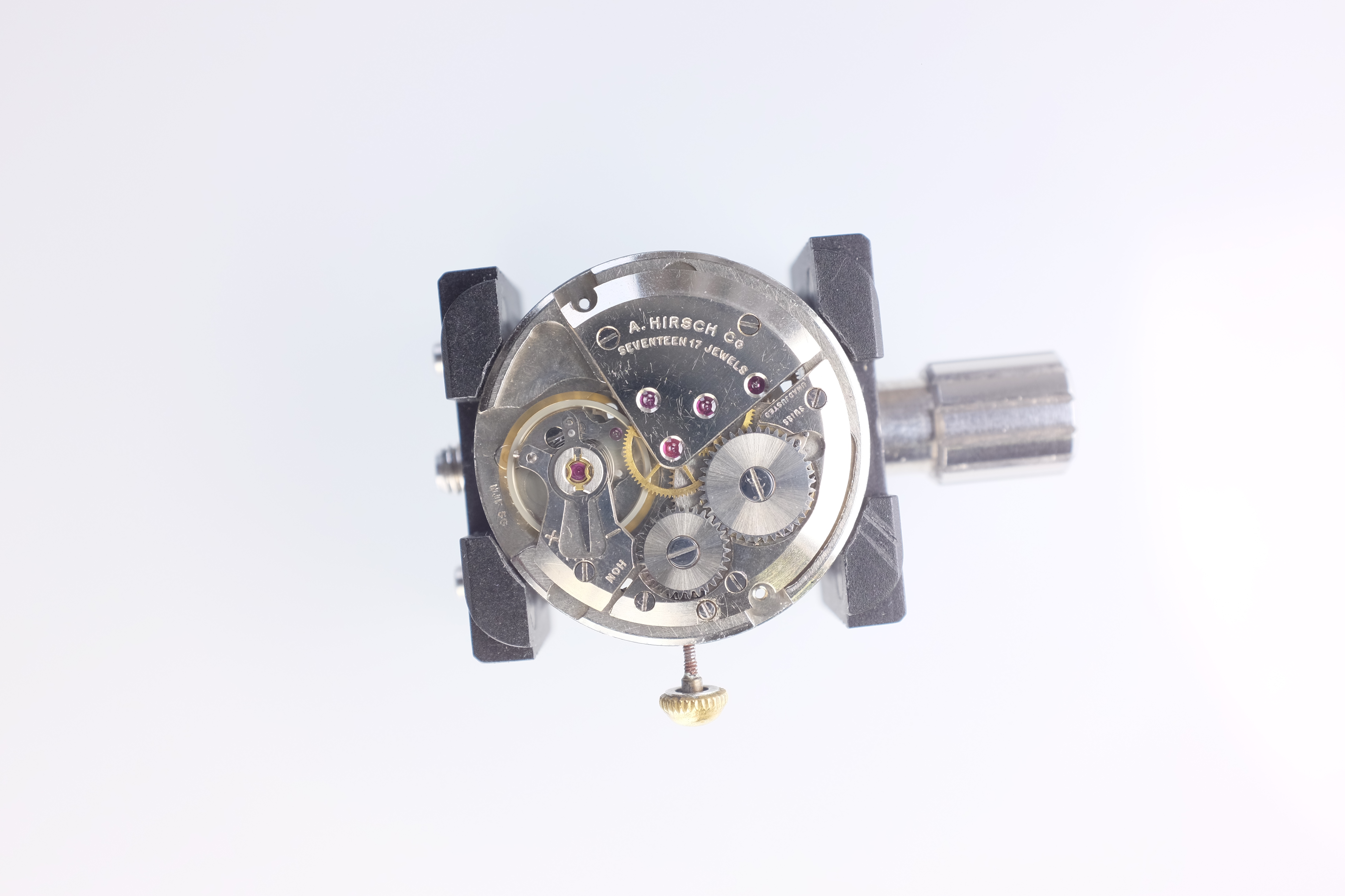
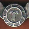
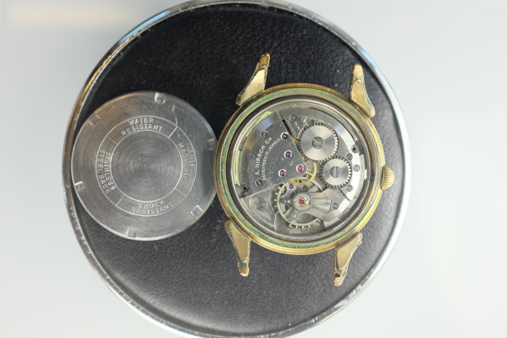
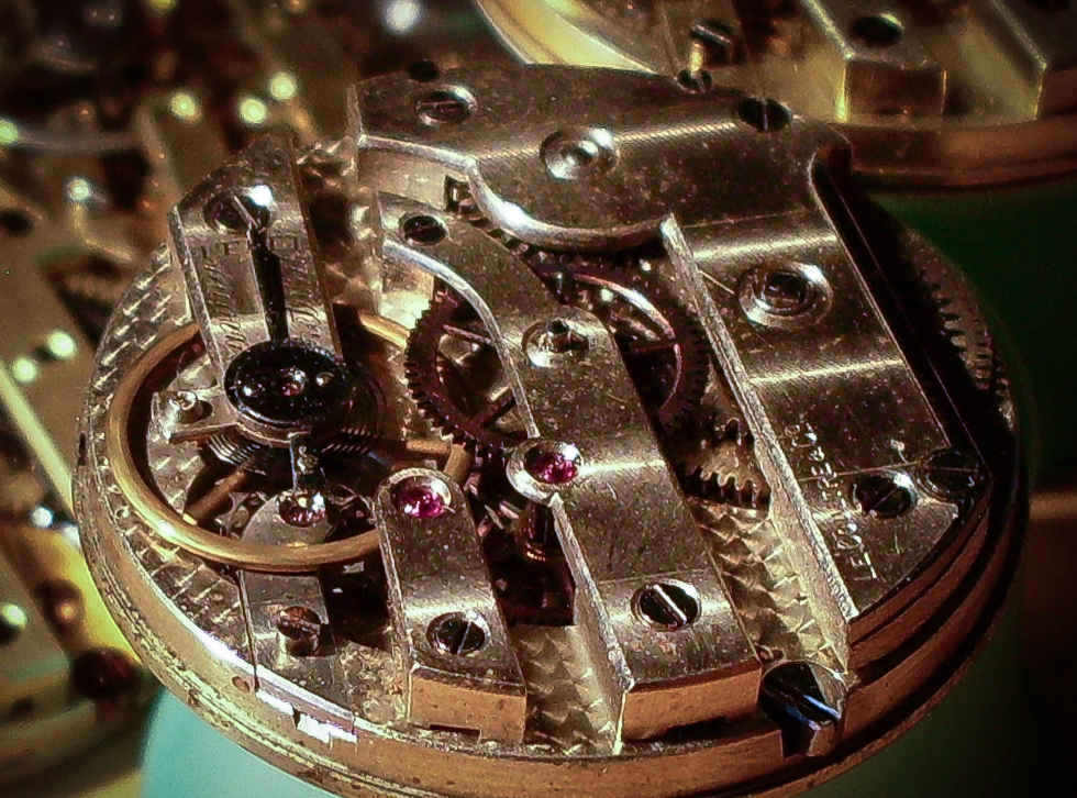
Hello oldhipply...happy to contribute if I can. For those unfamiliar with a cylinder escapement there is no pallet fork controlling the interface between the balance and the escape wheel...the escape wheel meshes directly with (if that is the correct term) or passes through, the balance wheel staff by means of an undercut hollow slot formed in the staff itself. This configuration is a form of 'dead beat' escapement known as a 'frictional rest'...as I understand it there is always a tooth in contact with the staff at any and all times. The problem I had was - as there is always a tooth in contact with the staff, I had to marry up the position of the tooth with the correct position it should be at during its cycle as it passes through the lips of the hollow - if not correctly aligned then the balance wont be able to transfer an impulse to the next tooth as it isn't releasing the tooth it's currently in contact with. An added problem is that since there isn't a pallet fork there is nothing to hold the normal turn and a half of the button to charge up the main spring to set the escapement on it's merry way - all power escapes immediately without the staff/cylinder in place. The solution was found in Fletcher: Watch Repairing as a Hobby: p57 of the 2012 edition...and was actually pretty simple once explained (thank goodness). I had to look for a marked slot on the rim of the balance, and then line this up with the middle dot of three set in the pillar plate. By good fortune all marks were present, and, as I was working on a movement that I knew had a perfect balance set up before I removed the cock, as soon as I set everything up and provided a half turn of power...off went the balance...! Learned something new...but if there is another way I'd appreciate the knowledge, as this movement is one of a job-lot of nine I've just picked up on ebay and the marks may not be present on those. Here's an image of the movement (sorry about the quality...using an old camera in poor light).
 1 point
 -
Hi all, Just been emailed the stems info below:- 065.453 - 1800 Length 065.533 - 2400 Length 065.557 - 2400 Length How do I measure length of stem required?1 point
-
Finished the lettering on the outside of the case today. Still waiting on tritium and luminous paint before reassembling though.
 1 point
 -
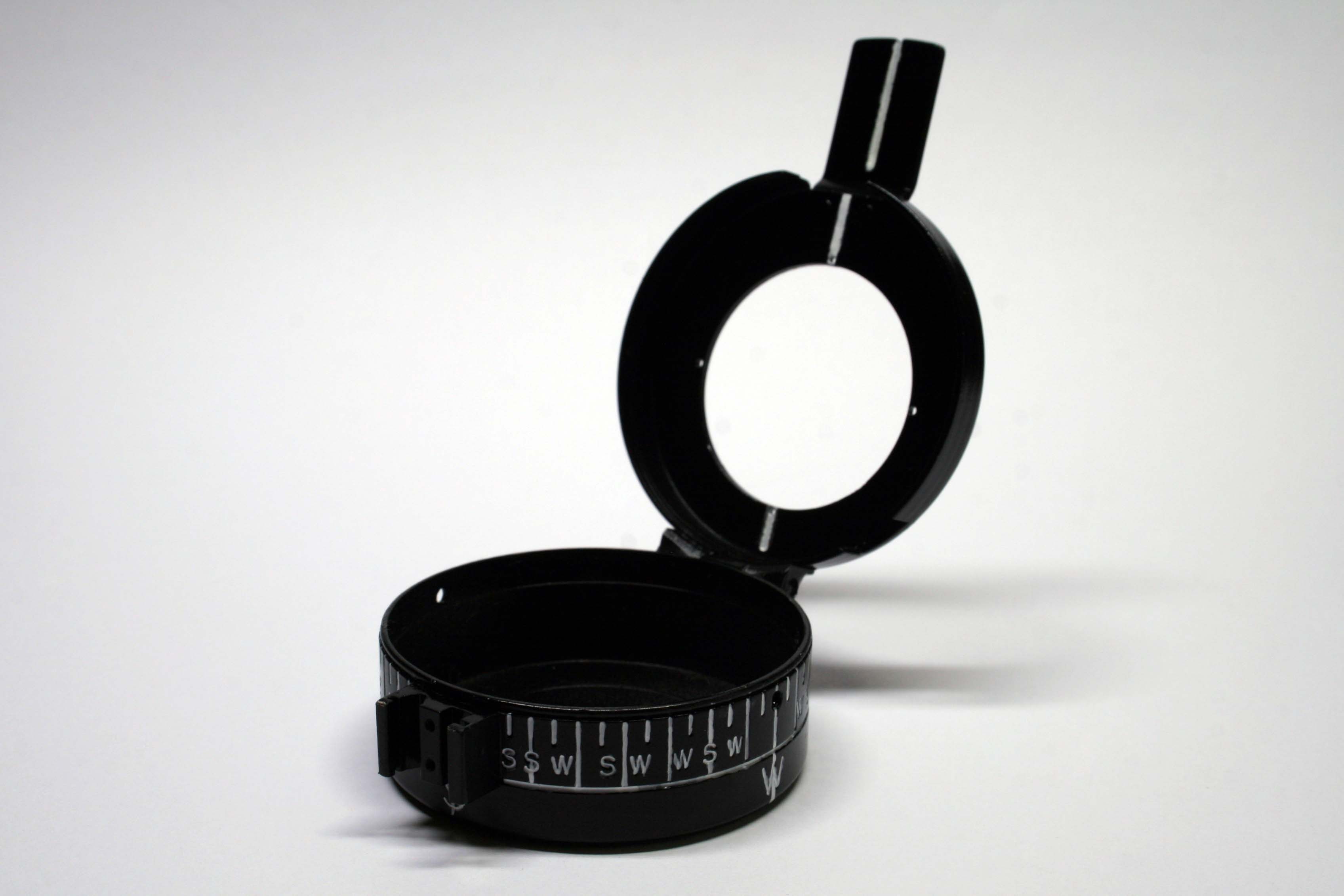
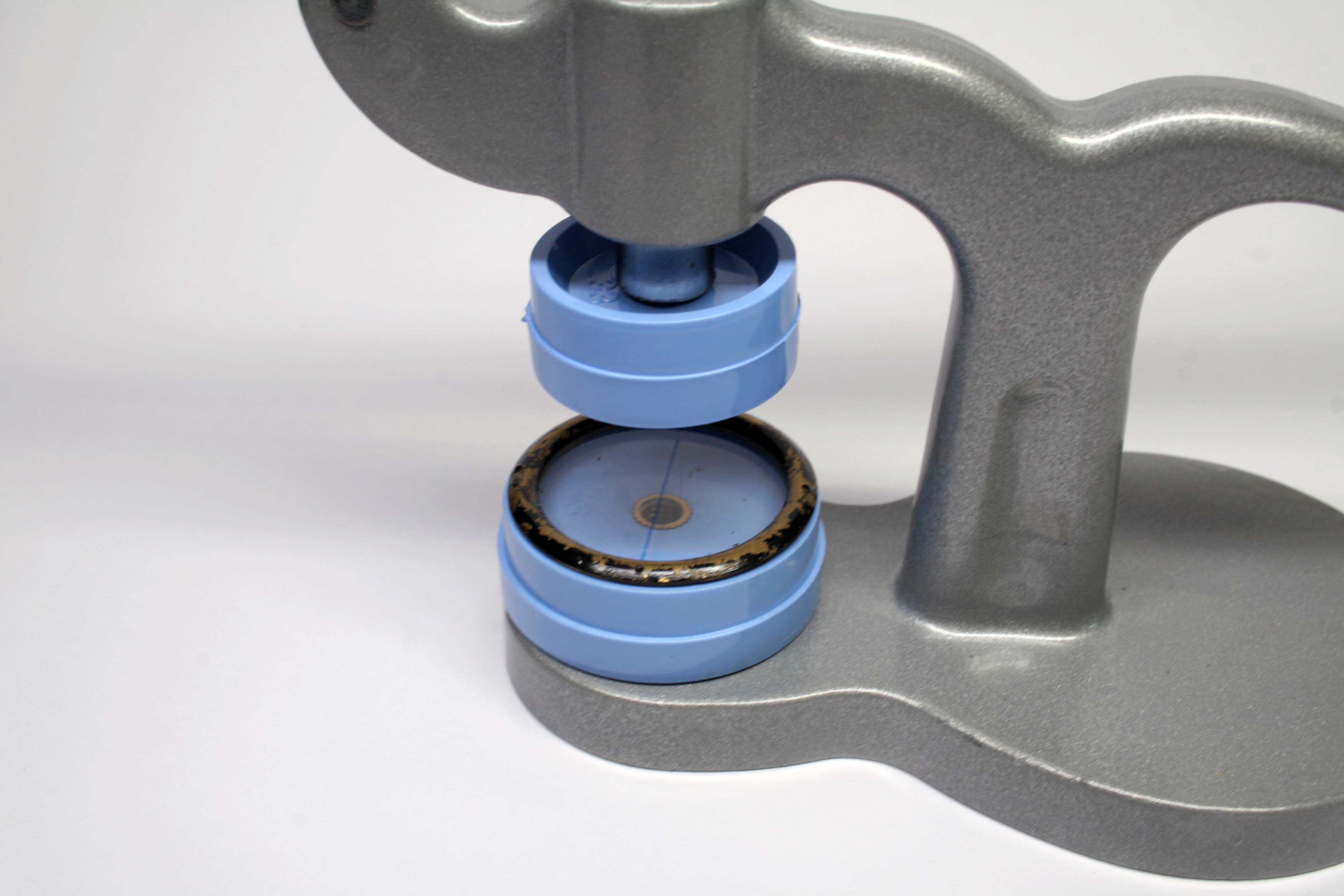
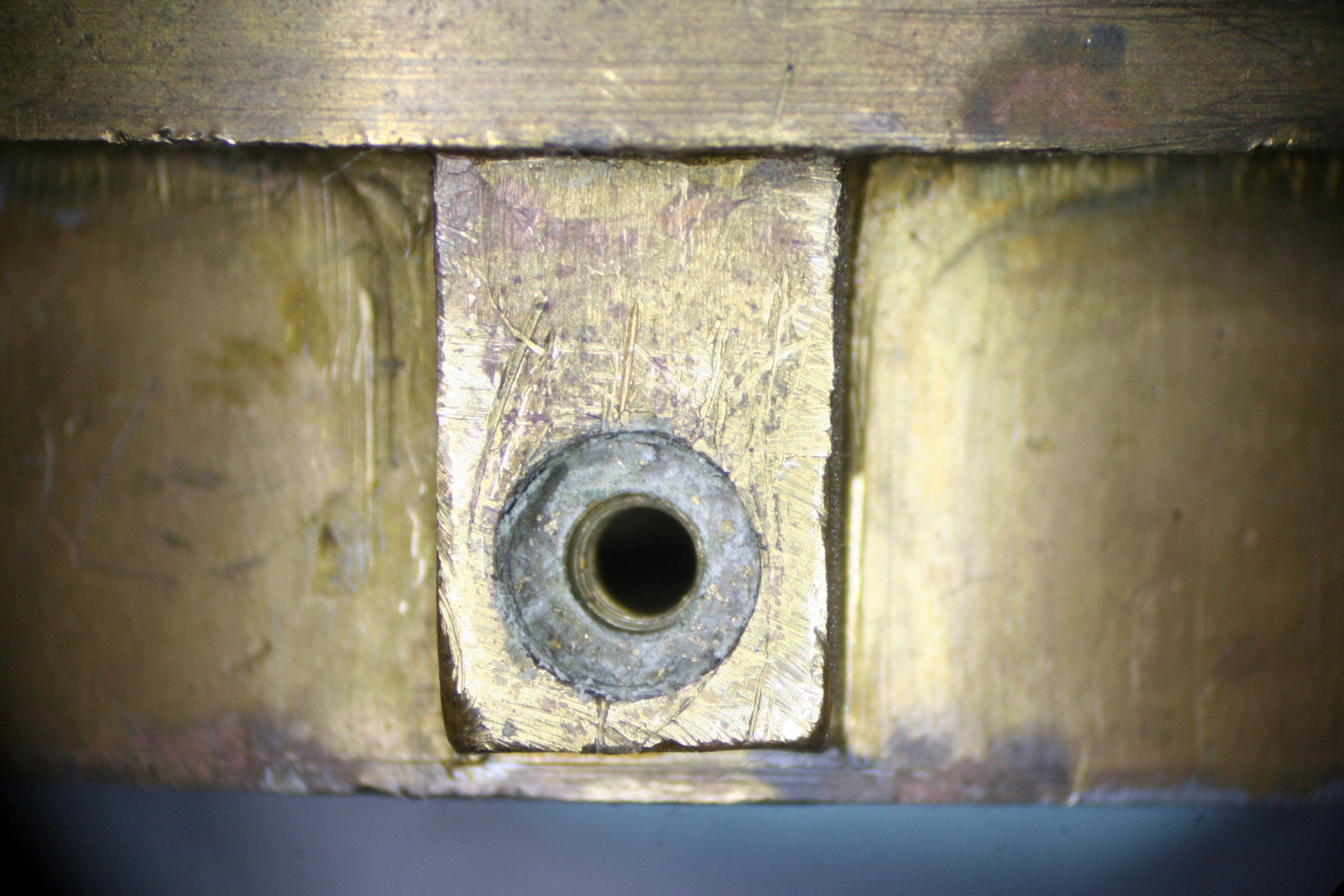
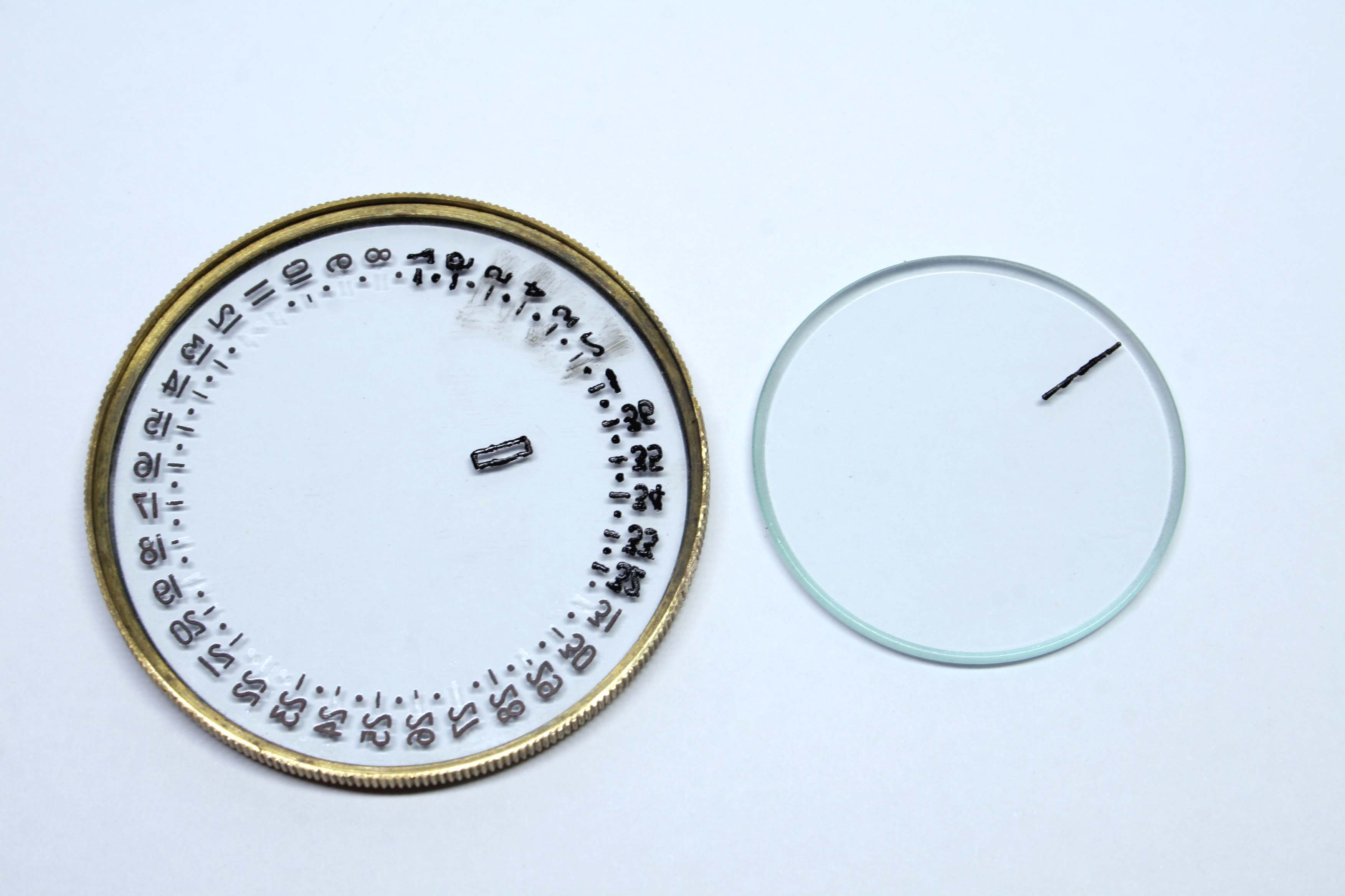
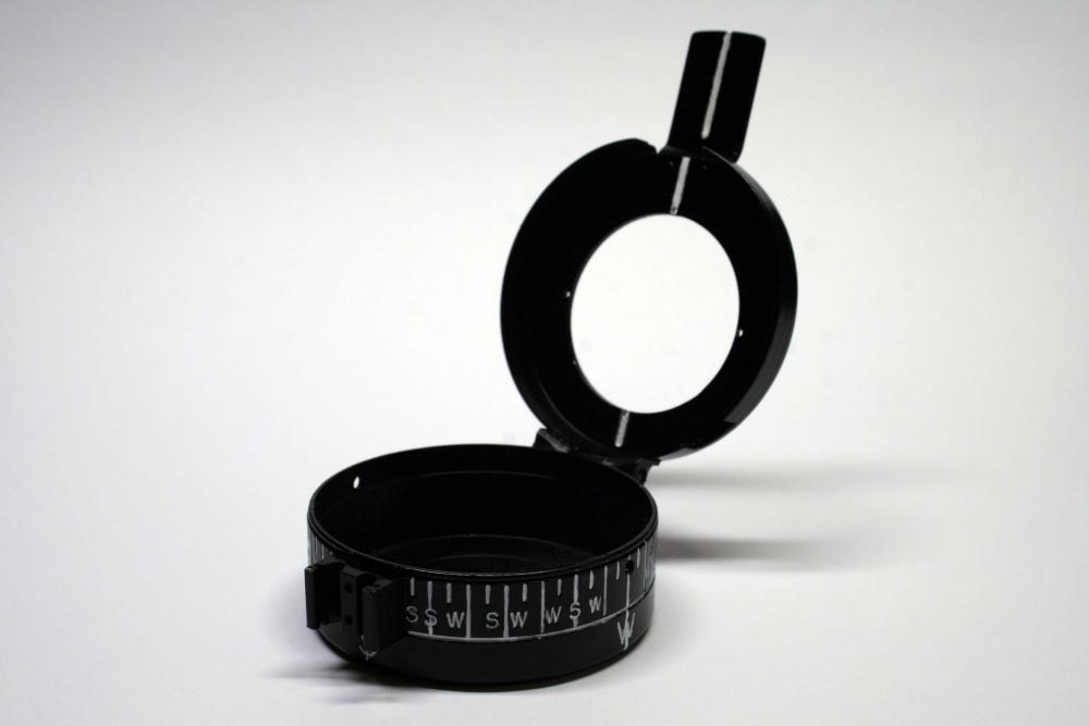
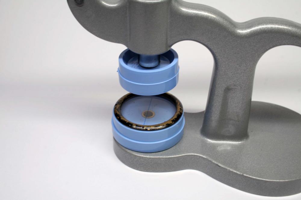
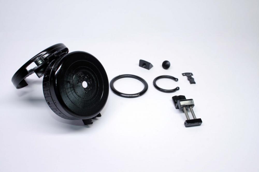
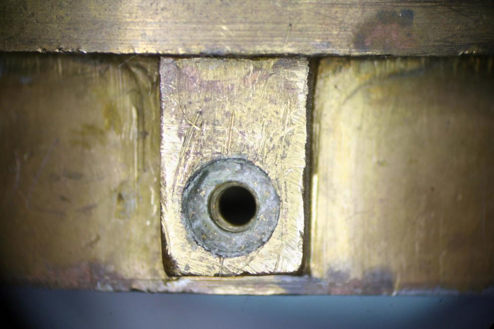
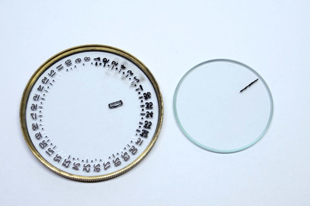
Update on the compass project- After stripping the case clear of paint I found that I forgot to strip the brass ring containing the top crystal, so the crystal was pushed out with the press and the ring stripped of paint. For whatever reason this particular part was not plated prior to painting but was simply black paint on brass. All the parts where then primed and painted with black lacquer. I tried to match the original look by selecting a semi-gloss but kind of wish I'd gone for a simple flat black. Regardless, I'm sure it will look fine in the end. I'll allow the lacquer to cure for a few days before repainting the markings on the exterior of the case in white. Setting the parts aside to let the lacquer cure, I returned to the compass bowl which had troubled me as the filler plug was secured quite well. A good soak in thinner and a proper sized screwdriver eventually freed the plug from the bowl. The fiber gasket was soaked with varnish as well and needed to be coaxed carefully from filling hole- I'll need to find a replacement that is just the right size. Below you can see the gasket still tightly glued in the hole. Lastly I turned my attention to the crystals. The crystal for the bowl was badly stained but this cleaned up with a bit of Dialux compound the rotary tool. Sadly the lubber line had become a bit faint during cleaning. The same happened with the degree markings on the rotatable crystal. Since the degree markings and lubber line are etched into the crystal, I simply needed to fill the etchings with a bit of black enamel. When the enamel dries, some thinner and pegwood will be used to remove the excess from outside the etchings. The crystal for the case lid was chipped and didn't survive being pushed out of the ring so a replacement was ordered yesterday. I also ordered a couple tritium tubes to replace the luminous radium paint. More to come soon.
 1 point