Jump to content

Recommended Posts

Posted (edited)
17 hours ago, yankeedog said:

are the heating coils removable?

I would say not. The entire assembly is and I was hoping to wire in the Elma Heater. Working on the assumption that you turn it on, it gets hot enough, you use it, then you turn it off again. I think the Elma element must be self regulating, or designed to operate at a certain temperature. Looking at the Elma spare part in the catalogue, there is a simple two-wire connection, same as this one.


IMG_1538.jpg

10.jpg

Edited by Moose
Added Elma Element image.
Posted (edited)

It looks like an old fashioned stove element to me, or possibly a very old kettle element. What are the dimensions of the space it needs to fit in?

Is the thing on the metal disk a thermal fuse, or a thermostat?

If it is a stove element, then you might be able to adapt a modern one to fit.

https://www.ebay.co.uk/sch/i.html?_odkw=6%40+stove+element&_sop=15&_osacat=0&_from=R40&_trksid=m570.l1313&_nkw=6"++cooker+element&_sacat=0


https://www.ebay.co.uk/itm/futura-kettle-element/192929243765?hash=item2ceb7aa275:g:9oIAAOSwH5xc6nm3

https://www.ebay.co.uk/sch/i.html?_odkw=5"++cooker+element&_sop=15&_osacat=0&_from=R40&_trksid=m570.l1313&_nkw=kettle+element&_sacat=0

You may need to add in your own thermostat to get these to cut out at a reasonable temperature, I'm pretty sure you don't need to boil a Rolex to get it clean.

https://www.ebay.co.uk/itm/5PCS-KSD301-Temperature-Switch-Thermostat-50-C-150-C-Degrees-Celsius-NO-NC/272790891850?hash=item3f839aad4a:m:mqXL_j-yLhgkW5JDPzzM-ug

Edited by AndyHull
Posted

Don't forget to ensure the thing is correctly earthed and that you are on an RCD protected circuit if you are testing any modifications, we don't want any hair raising incidents. Bangs and electric arc flashes may make good youtube content, but only if you are not part of the fireworks.

Posted (edited)

One further thought, if you are feeling particularly brave, you could purchase the nichrome wire and re-make the element, however you would need to know the specification of the original coil, its total hot resistance,  the gauge of the wire, its total length and the resistance per foot/meter of your chosen wire, so you could make something to match.

https://www.ebay.co.uk/sch/i.html?_from=R40&_sacat=0&_nkw=nichrome+wire&_sop=15

.. but a suitable kettle element (or perhaps two in series) and a suitable thermostat sounds like a much simpler substitution.

Edited by AndyHull
Posted

The basic dimension is shown in the photo, 75mm diameter. The other “thing on a metal disk” is the replacement heating element for the Elma RM80/90.

What would be useful to know (but not information I can find online), is what diameter the Elma replacement is and, if it is also a 240 volt element.

if anyone out there uses an Elma 80/90 it may be easy to see it in the bottom of the drying chamber. Or maybe a circuit diagram was supplied with the machine.

At £45 for an Elma element, I’m not sure I want to take the risk of buying one just see if it will work.

Otherwise, I will just as likely refurb it without a heater, and keep an eye open to see what might come up. I can always blow some hot air in from a hairdryer or something to get a drying effect.

Posted (edited)

it looks like all the sections are still there . it's just a coil of nichrome wire.Form the ends so that you can hook the sections together, it will work. for how long is anybody's guess, all you need is continuity.

Edited by yankeedog
content
Posted

I dont know about the ID of the coils but you could also cut sections , of oh say 12 AWG solid conductor wire and insert them inside the coils connecting the sections together.just so it's inserted for a few turns on each side. it will get hot.

Posted

I'm certainly going to explore some of the options mentioned here, thanks. From what I have found out, is that the heating output is around 200 watts, so not too much. 

Posted

If you decide to fix the existing heater I would tackle the problem as follows.

Count the coils.

Figure out the diameter of the coil.

The total length of wire in the existing coil is is Coil Circumference multiplied by number of coils or if you prefer...

2 * Pi * 'Diameter' * 'Number of coils' 

... since the diameter of the coil is much easier to estimate.

Nichrome wire is rated in Ohms/meter, this figure will be on the spool. The exact figure depends on the gauge of the wire,  so you should be able to work out the total resistance of a new coil.

The old coil can be cobbled together by twisting (not soldering) the coils together using bits of copper wire, per Yankeedog's suggestion.

You can then measure its approximate resistance, which should be close to what it was when new, or at least close enough for the purposes of this game.

You can probably get a rough estimate on the old coil's resistance using a micrometer to work out the wire gauge, then multiplying that by around the figure obtained from new wire of similar gauge, or even by guessing at 4 Ohms per meter.

More details here -> https://en.wikipedia.org/wiki/Nichrome

In other words, it should be possible to create your own coil, using a spool of cheap nichrome wire from ebay, a suitable round stick to form it on, and a little arithmetic. It can't be that hard, since the Victorians had this figured out long before we came on the scene. Mind you, they were still starching their hat brims with mercury, so perhaps health and safety wasn't their strong suit. 

Ohms law states that for resistive power in a DC circuit, Watts = V^2/R so you should be able to tell if you are in the right ball park with your calculations, based on that and your estimate of 200 Watts.

The fact that we are actually dealing with AC power and the fact that the resistance changes with temperature mean that this is an estimate, but probably close enough to tell if we are in gentle heating or explosive melt down territory.

I do, of course, completely absolve myself from any responsibility if your experiments set the cat's tail on fire, or result in lots of smoke and loud profanity. Also 240v AC is dangerous etc.

In summary, get the correct gauge of nichrome wire, wind the correct number of coils of the correct diameter, try it, but don't forget your safety glasses,  and work on a heatproof surface, since hot globules of exploding nichrome can be very "interesting".

Posted

All excellent advice.

BUT...

I have decided to purchase a modern 200W PTC heating element. It looks much like the one used by Elma in their new machines. It's about 75mm by 35mm rectangle shaped and can be mounted on the existing heatproof plate without issue. As standard is gives me 200W heat output at 220/240 volts and is self regulating - all I need to do is turn it on and off. 

To be honest, I did consider re-constructing the original, but then if more modern (and safer) technology is available, I may as well use it. I suspect it is a better solution that trying to hand produce a new element for a 50's or 60's heating element, as interesting as that might have been to actually try. Bottom line is that what I need is about 200 watts of safe, controllable heating. A PTC heater is the safest option for me.

Mind you, if anyone out there wants my old element to try to repair it, they are welcome to it for the postage cost from me to you.

If anyone is interested, the cost of the element is only £25 from Farnell, vs £45 to get the official Elma element from HS Walsh. For my money, it's exactly the same thing, only the Elma version is mounted on a steel plate. If you take a look at my earlier photo, you can see the PTC heater mounted on the circular plate.

200w 220/240v PTC Heater

Posted

I have recently purchased a National, Electric Watch Cleaning Machine. Attached is a photo for reference and identification of the model type. As can be seen, it has a fairly typical design, reminiscent of many other types, particularly Elma Super Elite. In fact, I do wonder which came first - the National or the Elma. My musings on this point later.

This is a very old machine, circa late 1940’s, 1950’s, but they seem to turn up sometimes on eBay, in various conditions ranging from the “beyond hope” and only really suitable as a donor for parts, and the “old but serviceable” and might-be-worth-a-punt-on machines.

This one fell into the middle somewhere, as it was a bit tatty and the heating element did not work. On the plus side, it had all its original cleaning fluid jars and lids, and the motor and speed control gave smooth, controllable spinning and no play in the bearings. I went to visit the seller to inspect it and we did a deal on the spot. This is not always possible on eBay, but as the seller had listed it as for collection only (due to its weight), it was a possibility on this occasion.

Once I had it home and gave it the once over, I decided that I would have to either do without heating for the drying stage, or find a replacement element. At the same time, it was very obvious that all of the original cabling was not safe to leave in place and it would all have to be removed and replaced. Any other electrical parts deemed unsafe would also be replaced as I inspected them. So - the idea of a restoration (of sorts) was born.

Now - it is not my intention to restore it to the point where it could pass current electrical safety standards, but I will be making it as safe as possible, without losing any of the essential character of the original machine. This is not going to be for resale, so being safe to use is an acceptable compromise, in my opinion. I will however, perform testing on it once the electrical work is done, to make sure that the essential aspects of earth leakage, earth bonds and polarity etc. are passed. (PAT Testing included.)

Whilst this is not likely to turn into another example of a superb restoration of an Elma Super Elite (as seen elsewhere on these forums), I hope at least to have at the end of it, a perfectly serviceable watch cleaning machine, and a restoration story - of sorts - of a vintage piece of English watch making and servicing machinery.

So first off - the before pictures. This one is a good view of the machine and its cosmetic condition, as purchased. The base is a heavy, cast alloy jobbie, with its original crackle paint job beginning to flake away in places, where the years of cleaning chemicals have attacked it,  but generally sound. The jars still had residues of cleaning and rinse chemicals present. The first wash jar (front left), was particularly grotty and can’t have been cleaned for years. Fairly ironic not to clean the thing, that cleans the things! Maybe it was just left unused and unloved for many years.

The mains cable was a cloth-bound type I have not seen in years and could well have been original as it still had the old UK wiring standard colours of red/black/green. Also adding to the vintage-ness, was a very old, Bakelite three pin plug. This must have been one of the first of its type as I have not seen one in brown Bakelite before! (And I am 62...)

Anyway, that’s enough for now, as I’m not even sure anyone wants to read much about such an old machine. If anyone is interested though, please add comments and I’ll add to the story as I make progress.

At the very least, I hope I have found a potential solution to finding/ making your own heating elements for these old machines, which could also include providing replacements for Elma Super Elite, RM80/90 HCS511 etc. Machines. More details later...

4E0834D1-5363-4131-8789-3A777EA54219.jpeg

  • Like 2
Posted

Looks like a fun project. I suspect there is little that would stop it passing modern electrical safety standards, so long as it is earthed, has the correct rated fuse, and a suitable mains cable attached.

How does the speed controller work? Some of these old speed controllers use an interesting arrangement of compressible carbon disks as a variable resistor.

I have an old Singer sewing machine that uses this arrangement, and a slightly newer Kenwood Chef mixer that uses a triac speed controller. Both are 1970s vintage, and both work well.

I would inspect any capacitors associated with the motor assuming there are any, and perhaps replace those with modern suitably rated ones, but the rest I would suspect is fine. If the motor runs, then it will probably keep running.

If this is a brushed motor, you might like to take the opportunity to clean the commutator with a bristle brush (not a steel wire one) and inspect the motor carbon brushes too. If the brushes are badly worn or damaged, they can kill the commutator pretty quickly.

  • Like 1
Posted

Well, where do I start? 

The speed control is a rather scary looking, three layer, open wound, wire-wound resistor/rheostat. As the mains connectors and the resistor itself is open from the underneath, that alone is enough to kill any chance of it meeting current standards. It would need to be completely replaced with an enclosed, mains motor speed controller to comply. Remember I did say 1940’s early 1950’s vintage for this machine. Not even close to 1970’s technology or practices.

The motor itself is fine and I will be inspecting the brushes and commutator as a matter of course.  But a quick visual inspection before purchase showed nothing for concern.

Here is a photo of the rheostat - in situ - for some idea... I have cut out some of the old wiring, which as you can see, is very old and fabric wound. I think Noah last used that stuff when he re-wired the Ark!

Bear in mind that this is what you are exposed to, as soon as you turn the machine over. This is how it was built! No guards or covers have been removed - none were ever built in. All that mains wiring and connections were visible and accessible at all times.

i will likely restore it as is, but then give some serious thought as to how to give protection from all that exposed stuff.

745CF2E3-100D-409F-AE9B-21DDF9BF325E.jpeg

Posted

Take it easy around that wiring, one thing I did think of after I posted is that some of the old wiring and indeed that rheostat may well contain asbestos. It will be safe enough unless you start chopping it about.

I would grab yourself a triac speed controller and bin the rheostat and its associated wiring.

There may be some suppressor capacitors that might need changing (although judging by the age of the machine, possibly not) and when the thing is running I suspect it will blast interference all over the radio spectrum, and buzz all over the local radio stations, but probably not enough to travel next door and annoy the neighbors.


Posted

No suppression in sight. Again, typical of its age I guess. I am also a licensed Radio Amateur so well aware of looking out for and solving interference problems. As well as not annoying the neighbours, I have no intention of wiping out my HAM radios either. ;)

All those plates you see on the rheostat almost certainly contain asbestos as mentioned, but they are bonded into those plates and are in very good condition for their age. I have "fabricated" a plastic insulation shield that encloses the rheostat and provides much increased protection. Having said that - I have also, already ordered a more modern 240v motor speed controller as well which will arrive today. I'm pretty sure that even with the "new" protective cover - I still would feel uneasy putting this back into service, so will likely panel mount the new controller in the space vacated by the rheostat. I hope the measurements I took off the replacement are accurate, as it should be a straight swap (if I am lucky). I may even be able to use the original rotary control knob and maintain a bit more originality...

Anyhoo...

Having cleaned and painted the base (with rattle-can black Hammerite) I turned my attention to sourcing a replacement for the heater. My main design criteria was that It had to perform like the original, and fit in place of the original. Clearly finding a spare part (even if likely, which it is not, not without cannibalising another original machine and goes against the grain somewhat), would mean that I was re-introducing an old (unsafe) element, after taking away an old (unsafe) rheostat. This did not make logical sense. So something new was needed.

Thee replacement heating element for the Elma Super Elite (RM80/RM90 etc.) are still available and they look like they would do the job, but are £45.00 plus postage from everywhere I could find them.

This is the specification for the Elma Machine and a photo of the spare part. The spec. shows that the power consumption of the heater is 200W, which is important to know. A quick examination of the wiring diagram (found elsewhere on the forum) shows that the heater has no external temperature regulation circuitry, and therefore must regulate its temperature by itself.

I recognised the heating element (the rectangular thing) as they are the sort of heater used for equipment cabinets etc. for frost protection and providing other low level heating needs. They are PTC elements, available in a variety of outputs and crucially, can be switched directly across mains voltage and self-regulate their temperature.

They are easy enough to find as the likes of RS Components and Farnell (other suppliers are of course available). So - I ordered a 200W 240V element for about £23. This would provide the perfect solution for my application.

Incidentally - As the Elma cleaning machines themselves are somewhat "vintage" these days, their original spare part heating elements are also likely (if they are not already) to become rare things. Therefore, knowing how to source replacements is useful to know. The Elma spare part comes with the circular metal disk (heating plate), but having a look at how the element fits onto it, looks like it just slides into those two grooves.

Anyway - the solution to my National machine was sourced and the next instalment will cover fabrication and installation.


IMG_0120.jpg

IMG_0094.jpg

  • Like 2
Posted

I forgot to actually show the original heating element. So in the interests of full explanations and detail, here are some photos.

The first shows the heater in the base of the front right corner. It is normally covered by an alloy copy of the glass jars used for cleaning, but with no bottom. (You can see this in an earlier photograph.)

The heater is a circular, pot-ceramic element, typical of its age, and contains a long 'nichrome' wire element to provide the heat. It is simply switched across the mains input to provide whatever it's rated output was. (I have not been able to find this out, but guessed when looking at this machine's descendants, for it to be around 150W to 250W heat output.)

There was a simple protective mica disk over the element, once again something of a give-away as to the age of this design, and also again, not particularly safe, as the Mylar is quite flexible and it would be easy enough to lift up at the side of the disk and touch the element whilst at mains potential.

After disassembly. you can see the channel where the heating wire fits. As can also be seen, is the reason for the auction listing describing the heater as non-functioning. The coil was broken in many places and sections were missing.

Replacing this to get the National Electric Watch Machine's drying capability back in action, was seen as essential during my restoration/repair/refurbishment of this fine antique! (Slightly tongue in cheek there... :P)

8.jpg

IMG_1538.jpg

  • Like 1
Posted

Some more of the "before" photos.

Rear facing shot.

Motor rating plate.

Swing-arm and clamp. Very old fabric sheathing on the twin-flex wires to the motor.

Rheostat housing and motor speed controller.

2.jpg

3.jpg

5.jpg

6.jpg

Posted

Interesting, I may look at using a PTC heater on my 3D printer bed. I suspect that since it is a purely resistive load, it should be possible to use one of the inexpensive triac motor controllers and a few resistors and a NTC thermistor to give rudimentary maximum temperature control.  

Something like this.

https://www.ebay.co.uk/itm/NEW-200W-AC-DC-220V-77x62x6mm-PTC-Thermostat-Aluminum-Heating-Ceramic-Heater/262875357015?epid=892675962&hash=item3d34979f57:g:PhUAAOSwwVBbeDLn

... and this ...

https://www.ebay.co.uk/itm/Mini-DC-5A-Motor-PWM-Speed-Controller-3V-35V-Speed-Control-Switch-LED-Dimmer-A/254124806948?hash=item3b2b04d324:g:BLoAAOSwSYRbnMMT


...  controlled by a conventional relay by the 3D printer controller. I suspect it would heat a lot quicker and provide more even heat than the ubiquitous aluminium PCB types. 

Posted

Last two pictures for now.

The cleaning baskets are what you expect from this machine and have been seen before on the forums. I was intrigued by these, as in most of the threads, it is said that they measured around 80mm or thereabouts, and that two of the current Elma parts dividers would fit inside the National's outer basket. This sounded like a good idea and I very nearly sourced a couple when I got the machine. I'm glad I didn't!

When I got it home, I measured it to make sure all was as I was expecting - but it was not. The overall diameter of these baskets is 64mm - the same as the Elma, therefore the Elma dividers could not fit inside the National Basket as it's internal diameter is only around 55mm.

SO - as others have posted, their models did indeed come with 80mm fittings, as evidenced by dimensioned photographs. It is also true that mine came with a 64mm fitting. SO, a little more digging may be needed to see what was fitted as standard.

IMG_0116.jpg

IMG_0117.jpg

Posted
8 minutes ago, AndyHull said:

Interesting, I may look at using a PTC heater on my 3D printer bed. I suspect that since it is a purely resistive load, it should be possible to use one of the inexpensive triac motor controllers and a few resistors and a NTC thermistor to give rudimentary maximum temperature control.  

Something like this.

https://www.ebay.co.uk/itm/NEW-200W-AC-DC-220V-77x62x6mm-PTC-Thermostat-Aluminum-Heating-Ceramic-Heater/262875357015?epid=892675962&hash=item3d34979f57:g:PhUAAOSwwVBbeDLn

... and this ...

https://www.ebay.co.uk/itm/Mini-DC-5A-Motor-PWM-Speed-Controller-3V-35V-Speed-Control-Switch-LED-Dimmer-A/254124806948?hash=item3b2b04d324:g:BLoAAOSwSYRbnMMT


...  controlled by a conventional relay by the 3D printer controller. I suspect it would heat a lot quicker and provide more even heat than the ubiquitous aluminium PCB types. 

Are you sure? That linked PTC is rated for 220V AC or DC, but your controller is only rated to provide 3V to 35 DC output. My guess is, it's nowhere near the PTC's operating voltage.

That PTC element is designed for a 220V input. You either need a PTC with a lower voltage DC input, or a controller with a higher rated output.

This is the one I will likely use. its a PWM AC Motor speed controller. adjustable from 50v to 220v output and 2kW max. (Although I personally would take with a pinch of salt the 2kW rated output. Mind you, I only need less than 800 Watts or so anyway.)


PWC.jpg

Posted

Well spotted. I included the wrong link. Something 220V AC rated, more like this perhaps (although I don't think I would try to crank the stated maximum 25A out of them) ->

https://www.ebay.co.uk/itm/2000W-AC-Motor-Speed-Control-Controller-Adjustable-Voltage-Regulator-50-220V-YJ/382850170457?epid=3020717857&hash=item5923a5fe59:g:gKQAAOSwAuZbN2gD
 

I already have a couple of similar ones "in stock" as it were, i.e. lying around in one of my component bins.

Posted

Yes - I know what you mean about posting the wrong links... I won't go into a time when I posted the wrong link to something... Oops. :ph34r:

I think that one is the same as the one I am likely to use. And I agree about the power rating looking, well,  let's just say "optimistic" and leave it that. I think for the National Watch Cleaning Motor, I'm unlikely to need more than 100 watts of motor power anyway, so that would be more than adequate.

Thanks for the comments so far.

Posted

I haven't pulled the trigger on a watch cleaning machine, yet, but if/when I do, I suspect I would go for something vintage, 'cos half the fun for me, is in restoring it.

I've still to bring home a colour laser printer I picked up on ebay, which is currently in my office, and which is no doubt larger than my wife expects, so I may need to wait for a suitable diplomatic cooling off period before I introduce any more junk useful items in to the mix.

  • Haha 1
Posted (edited)

With the PTC Heating Element arrived, it was time for some metal bashing. 

Actually, it briefly got a bit more "high tech" that that. I needed to try and replicate the Elma Heater, based upon what the Elma spare part heater looks like from catalogue pictures. A quick estimation on my part seemed to indicate a mounting plate size of around 90mm diameter (the element being 75mm on it's long side). Where to sort it from? 

A quick conversation with an old work-mate turned up the opportunity for a catch-up and a bit of "metal bashing" for the cost of a light lunch.

A bit of mild steel around 1.5mm think was run through his laser/plasma cutter in no time and I had my mounting plate. Once back home, it was drilled to attach the heating element. So that job done, now to mount it in the machine.

In my opinion, it's not a bad replication of the original Elma spare part and I cannot imagine that it would be any less efficient.

SO - if you cannot get hold of the Elma Heating element, all you need is a relatively cheap PTC Heating element, and a good mate with around £35,000's worth of plasma cutter!


IMG_1554 (1).jpg

IMG_0094.jpg

Edited by Moose
  • Thanks 2

Join the conversation

You can post now and register later. If you have an account, sign in now to post with your account.
Note: Your post will require moderator approval before it will be visible.

Guest
Reply to this topic...

×   Pasted as rich text.   Restore formatting

  Only 75 emoji are allowed.

×   Your link has been automatically embedded.   Display as a link instead

×   Your previous content has been restored.   Clear editor

×   You cannot paste images directly. Upload or insert images from URL.


  • Recently Browsing

    • No registered users viewing this page.
  • Topics

  • Posts

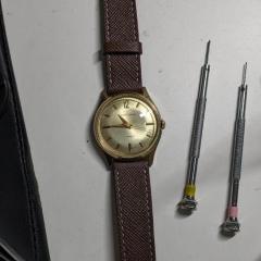
    • Hi All, I’m having a hard time finding a balance assembly or even a working donor movement for a Gruen 330.  Any leads appreciated.   Gruen doesn’t stamp the caliber number of the movement but lust in the case back.   
    • Why do you think this is Fontainemelon ?  The balance staff you will need to source separately.  But first it's important to accurately identify what you have there. Research Ebauches Sa, see who was in group, to find the brand that made this movement. 
    • Hi Watchrepairtalk, I have some questions about part sourcing I was hoping someone here might be able to help with. I'm working on an FHF 180 movement with a broken balance staff, broken regulator pins, and damaged cap jewels (both top and bottom). Some Googling says that this is similar to other FHF calibers like 150s, 160s, 180s and so on but I can't figure out what the functional difference is between these movements.  Is there any reason I wouldn't be able to acquire a donor FHF 150 or similar (with no shock protection) and use parts from that or would it be smarter to source replacements individually? Also are there any sources someone could recommend to get bulk cap jewels like this? Thank you for the help!
    • Hello and welcome to the WRT forum.
    • interesting video nice to see the machine what it can do now I wonder what it costs and I'm sure it's not in my budget. Plus the video brought up questions but the website below answers the questions? What was bothering me was the size of his machine 4 mm because I thought it was bigger than that? But then it occurred to me that maybe they had variations it looks like four, seven and 10. With the seven and 10 being the best because way more tool positions in way more rotating tools. Although I bet you all the rotating tools are probably separate cost https://www.tornos.com/en/content/swissnano   Then as we been talking about Sherline. Just so that everyone's aware of this they have another division their industrial division where you can buy bits and pieces. I have a link below that shows that just in case you don't want to have the entire machine you just need bits and pieces. https://www.sherline.com/product-category/industrial-products-division/   Let's see what we can do with the concept I explained up above and bits and pieces. For one thing you can make a really tiny gear very tiny like perhaps you're going to make a watch. Then another version the center part is not separate it is all machined from one piece. Then fills gear cutting machines have gone through multiple of evolutions. A lot of it based on what he wanted to make like he was going to make a watch unfortunately eyesight issues have prevented that. Another reason why you should start projects like this much sooner when your eyesight is really good or perhaps start on watches first and then move the clocks then local we have from the industrial division? Looks like two separate motors and heads. Then it's hard to see but this entire thing is built on top of a much larger milling machine as a larger milling machine gave a very solid platform to build everything.   Then like everything else that had multiple generations are versions the indexing went through of course variations like above is one version and the one below was the last version. Now the version below I mentioned that previously and somewhere in the beginning to discussion and somebody else had one in their picture. As it is a really nice precision indexing. Then I wasn't sure if I had a the watch photos here is his unfinished watch. No he wasn't going to make a simple watch like none of his clocks were simply either what would be the challenge and that.    
×
×
  • Create New...