Leaderboard


Popular Content
Showing content with the highest reputation on 04/22/18 in all areas
-
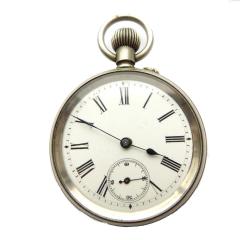
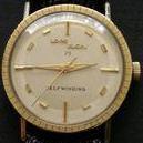
The movement is a Aegler who made many of the early Rolex calibres Aegler was based in Rebberg in switzerland so these movements are described as Rebberg movements, they where also supplied by Aegler to other watch companys and where not exclusive to Rolex, Gruen also used this movement badged as a calibre 806. If you want to research your movement, this would be a good start point, http://www.vintagewatchstraps.com/aegler.php2 points
-
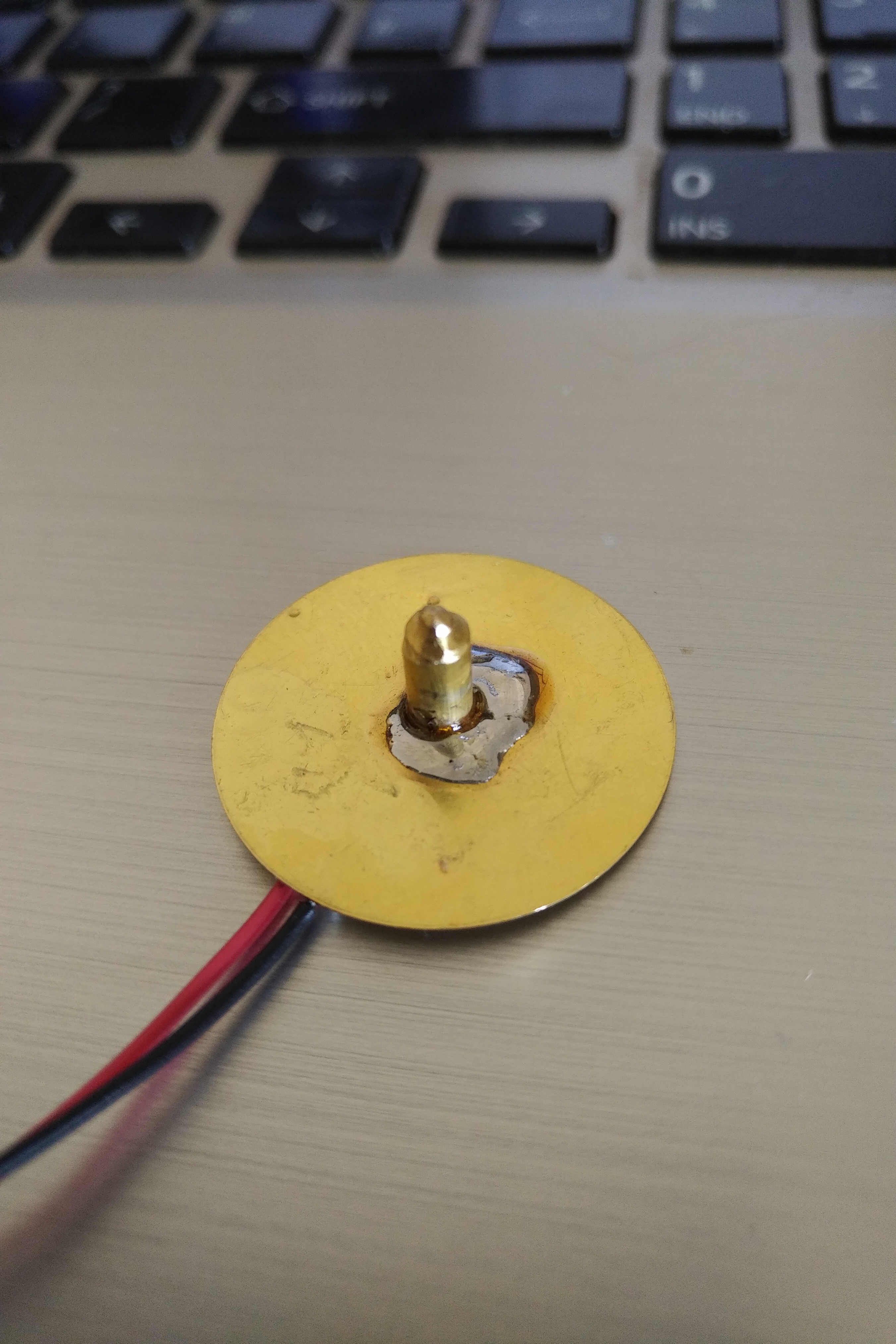
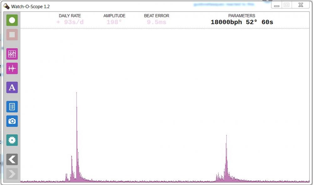
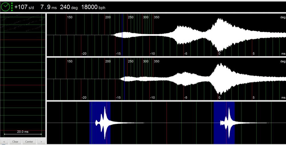
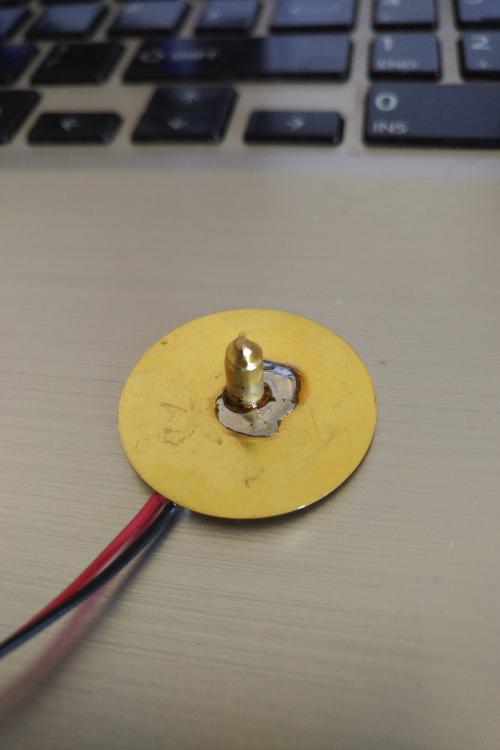
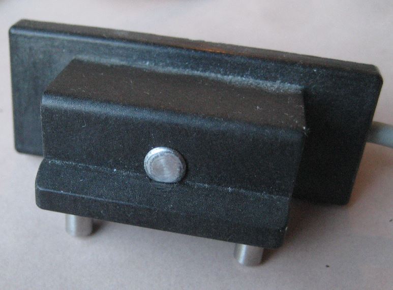
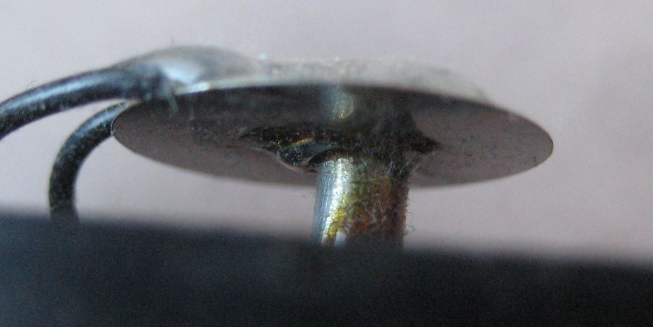
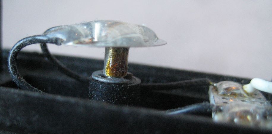
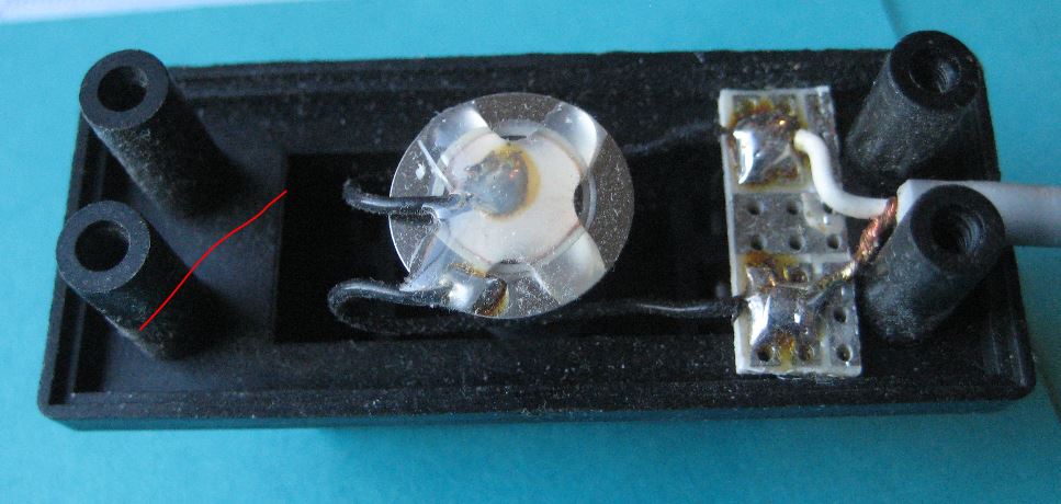
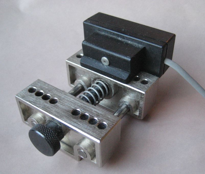
Not getting much time to fiddle with this (or the watches) lately, but managed to try the piezo again. I soldered a brass pin to the piezo and when that is contacted with the stem or backplate of a movement it generates a good signal. No preamp - just wired direct to the laptop mic socket. This is just me holding the movement on the pin on the sensor. Depending on time I want to try and make a better holder, then I compare mic setup's better.
 1 point
 -
if there's no suitable company in Sweden then maybe a company in the UK would be more amenable. There's http://www.crystalfit.co.uk/ who can make bespoke crystal shapes and "can form complicated shapes and profiles". No harm getting a quote I guess and see if it's in line with the one from the US.1 point
-
use an on-ship service like https://secure.comgateway.com/home when you sign up with them, they give you a US address. you ship to them and then ship it to yourself.1 point
-
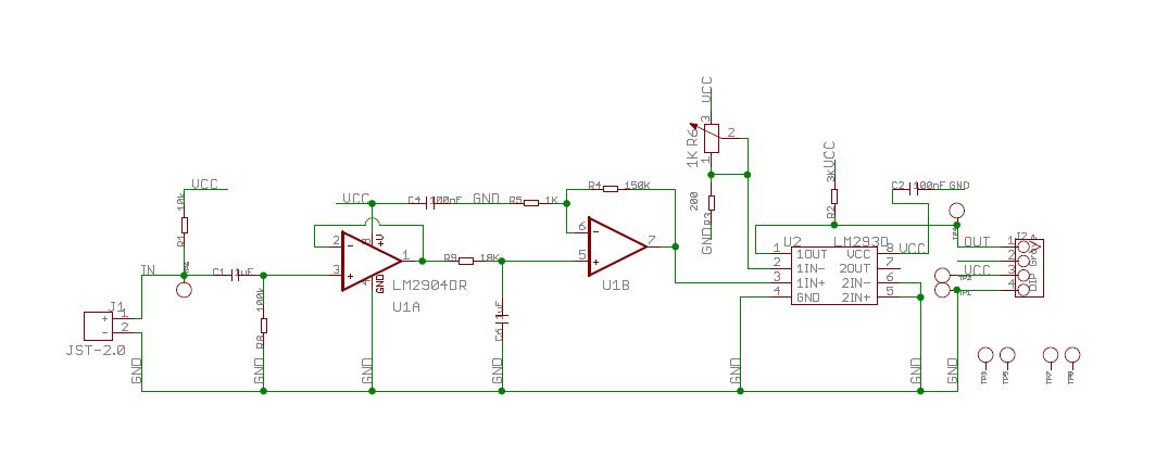
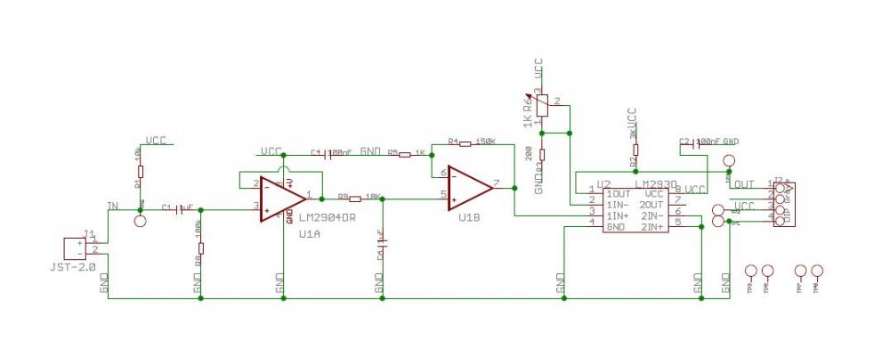
So documentation is interesting the picture of yours doesn't match the picture of the one at the link or the documentation is. But I'm guessing that the circuits are the same. Then the description gives the impression that it might be a linear device where it is actually outputting a digital signal. I'm attaching the schematic which may be similar to yours probably is. So a dual op amp two amplify the sensor outputting to a digital comparator. So just tap into the output of the op amp use a capacitor before feeding into the computer. http://wiki.seeedstudio.com/Grove-Piezo_Vibration_Sensor/
 1 point
 -
These little guys look fairly nice as well for not too much money. http://www.julesborel.com/s.nl/it.A/id.32628/.f
 1 point
 -
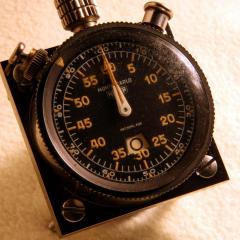
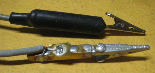
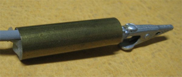
One of the problems with the timing machine software discussion is how many pages have accumulated. So interesting ideas or pictures have been shown such as the two pages below. So I'm extracting out some of the keys stuff. So the clip on microphone is relatively simple to make As you can see from the images below. There's more to it than just a disk attached to the alligator clip. Also attached images of their watch pickup. On one of the pages below there is also the Microset version of the watch pickup. Basically the same concept protruding pin to transmit the vibrations the disc. So the disc itself is protected by being a box and isolated from audio sounds. It's why I think of the TimeTrax version they put the hot glue across the desk to minimize sound pickup as a guess. Strangely enough the Microset version just has a disk. So better than the disc would be the Piezo Bi-Morph Vibration Element Found at the link below. Then if we can figure out a design 3-D printers would allow complex designs to be made cheaply. His 3-D printers are more common on people's kitchen tables now or their companies out there now make stuff for you that opens up a nice possibility. https://www.watchrepairtalk.com/topic/3002-d-i-y-watch-timing-machine/?page=6 https://www.watchrepairtalk.com/topic/3002-d-i-y-watch-timing-machine/?page=21 https://uk.rs-online.com/web/p/vibration-sensors/0285784/
 1 point
 -
Welcome.All good wishes. Like dadistic, I have been known to spout off so ignore a lot of what i say. There are however some very knowledgeable people here. Cheers, Mike.1 point
-
Greetings and Salutations! Yes, be careful not to learn form the unskilled like me, who will spout off anyway The trick is learning to spot the difference!1 point