Leaderboard


Popular Content
Showing content with the highest reputation on 09/10/22 in all areas
-
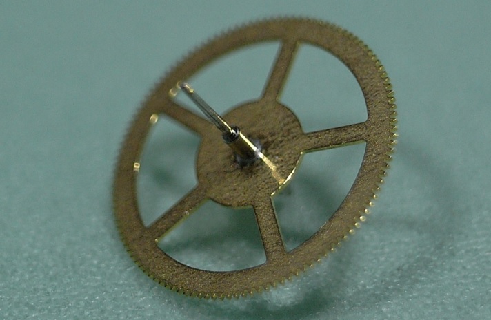
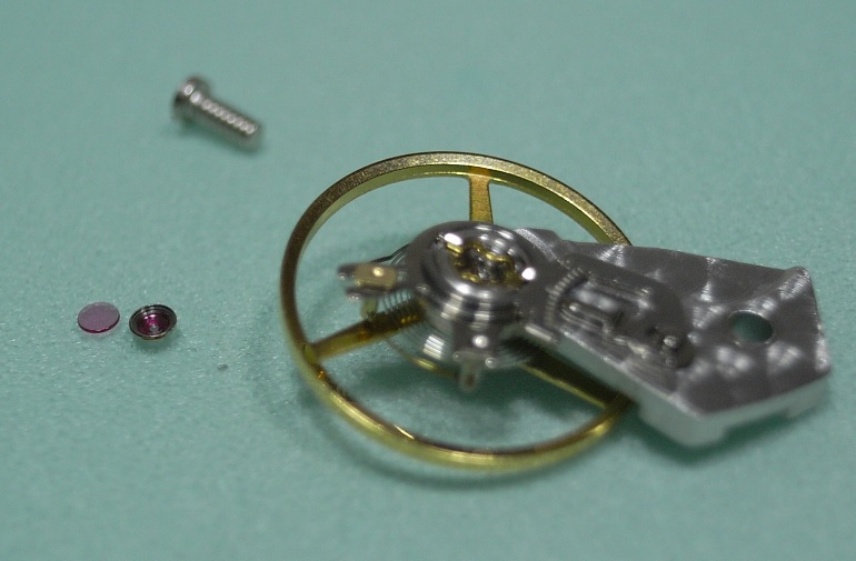
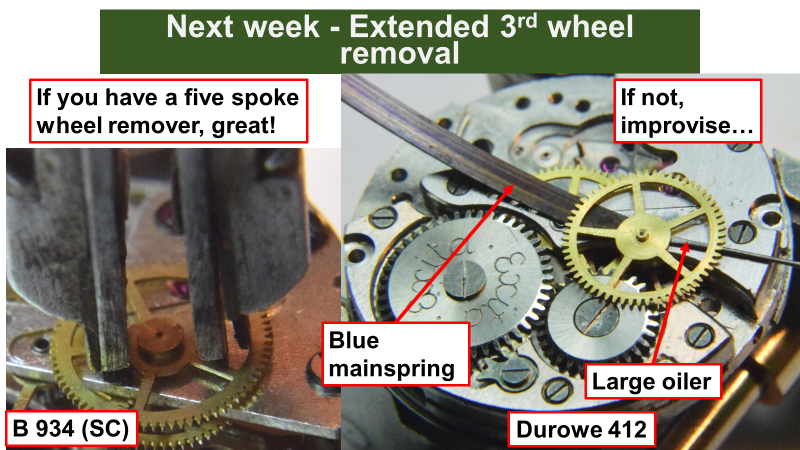
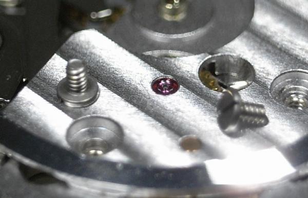
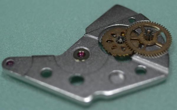
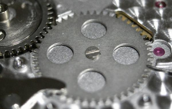
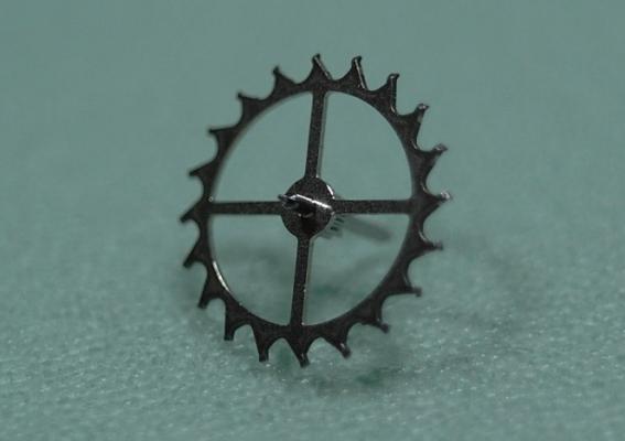
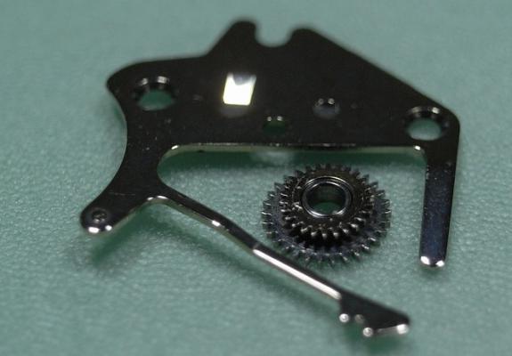
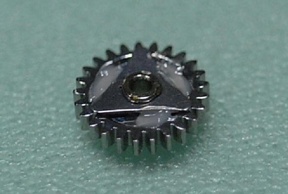
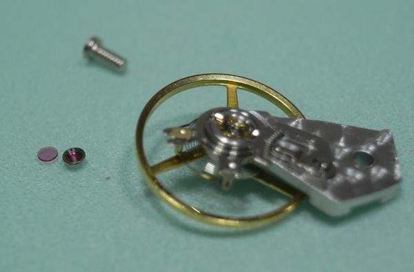
Just make sure you pry off the wheel from the central hub, otherwise you'll bend the wheel removing it. When the wheel is removed check that it is totally flat before assembling back on with a staking tool. Also, the wheel you need to remove is the one with four spokes, not the five spoke wheel, the five spoke wheel is part of the wheel train. So, when staking back the four spoke wheel it is critical you get the height correct so it engages with the sweep second pinion exactly in the middle of it
 6 points
 -
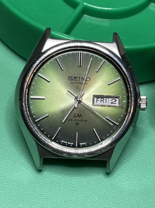
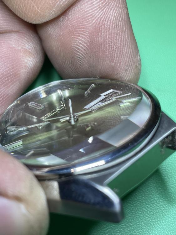
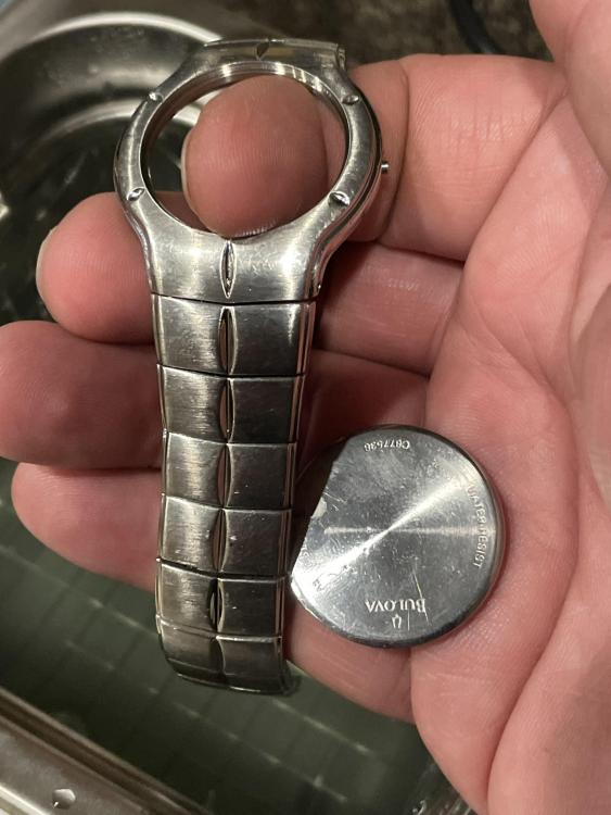
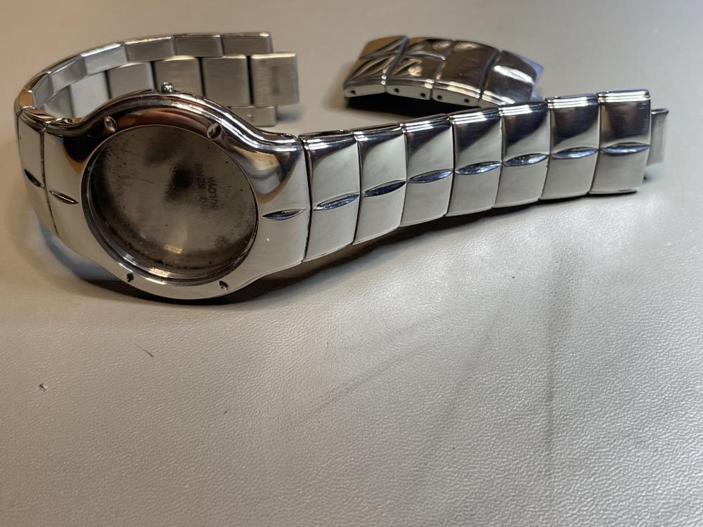
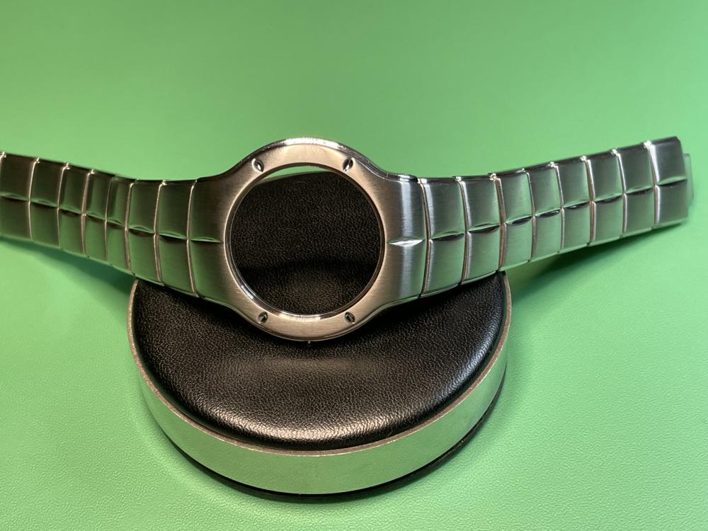
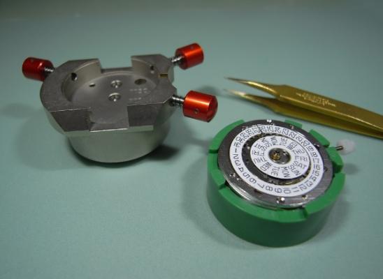
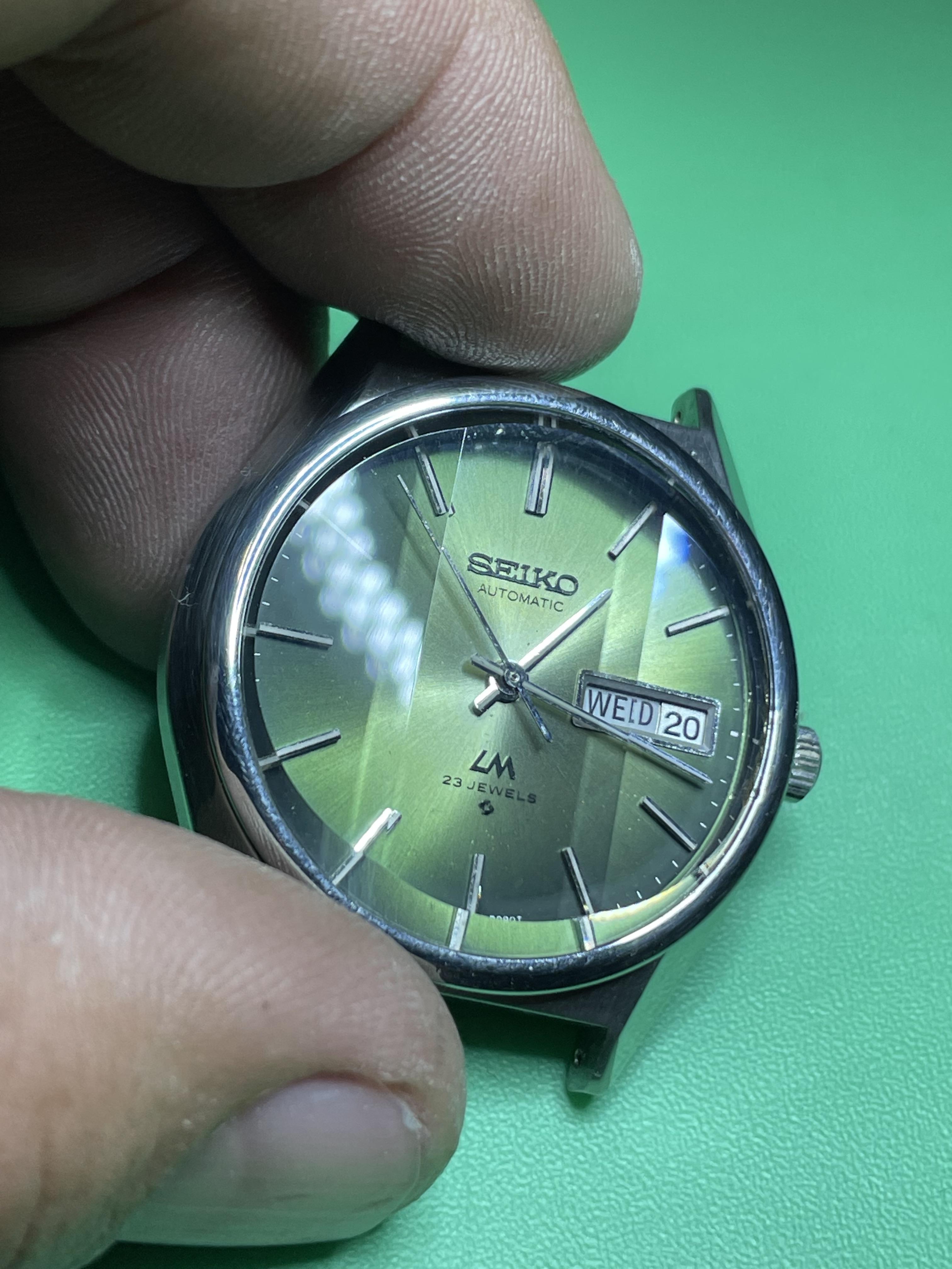
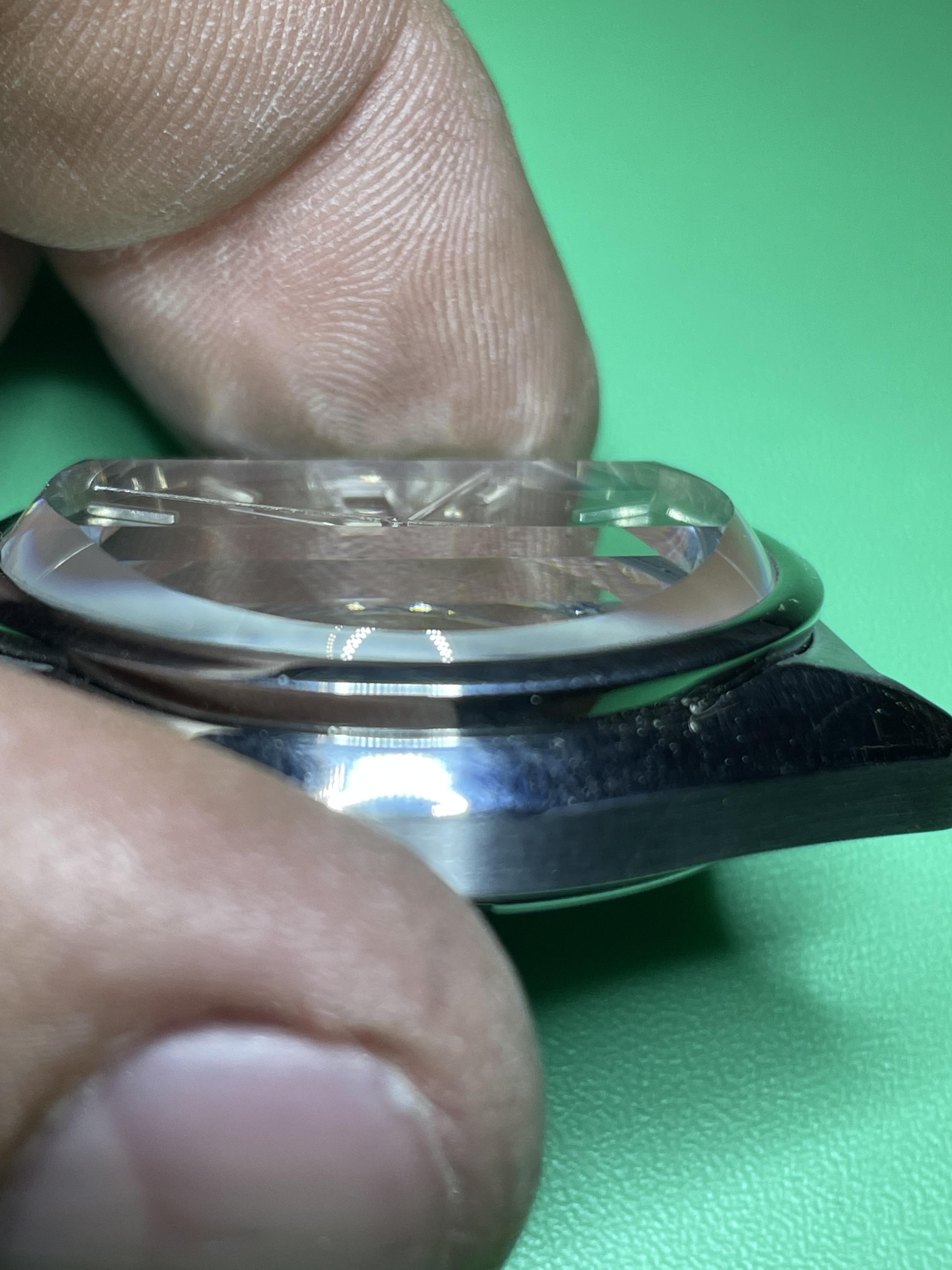
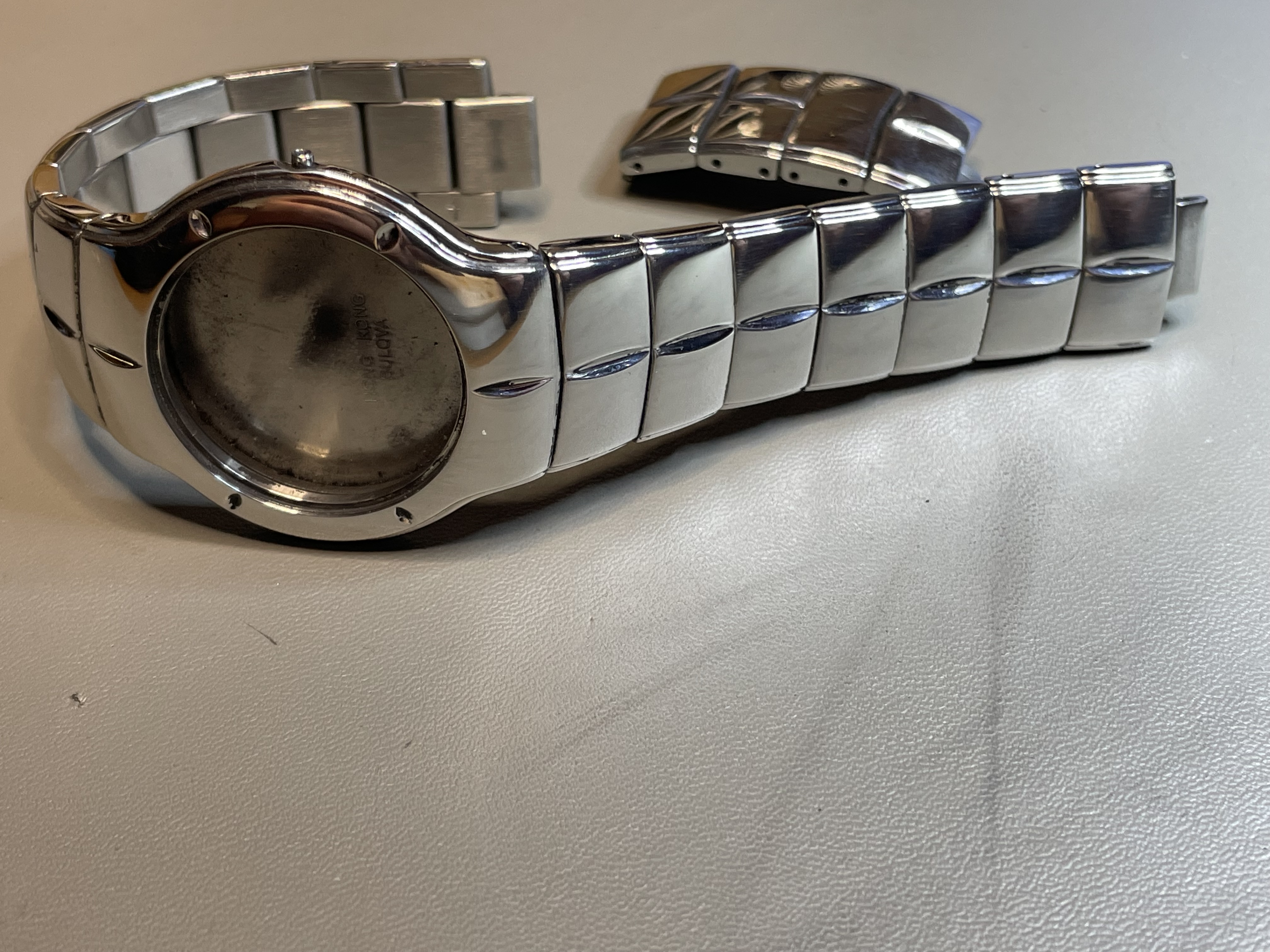
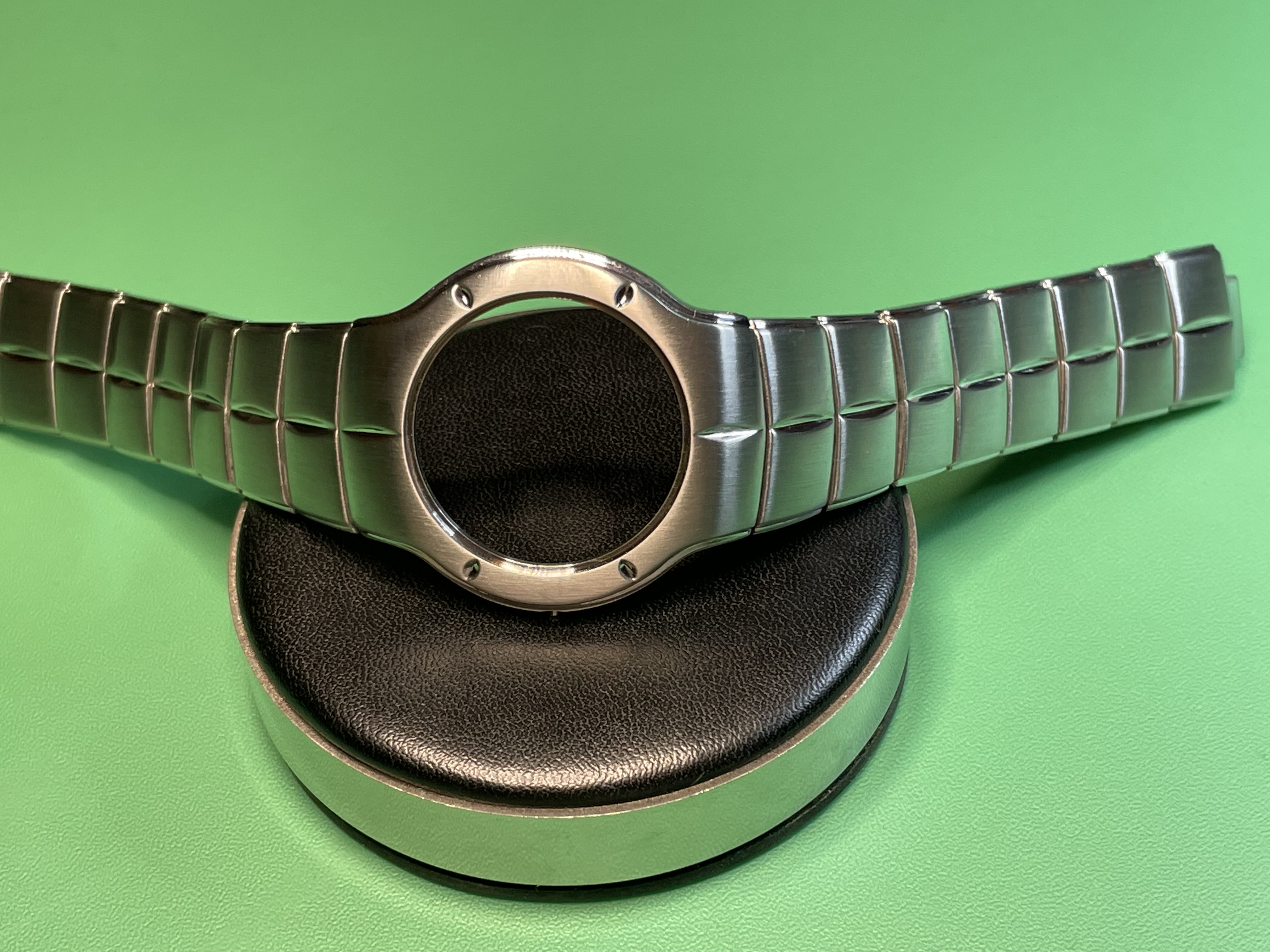
I had previously documented on an earlier thread where I was working on a 1972 Seiko Lord Matic. Here's a photo if you remember the other thread: An original faceted crystal was nearly impossible to find, and when I did finally locate the correct part number for sale, it was very expensive. While doing my research I came across another Seiko part number that by the numbers seemed like it should fit, although none of the documentation I found stated that it was for my particular watch. The 2nd part number was available for a very reasonable price from Cousins, but unfortunately they did not have a picture of it so I took a gamble and ordered it. It arrived yesterday, and when I pulled it out of the package I was very pleased to see that it was of the exact same shape and facet profile of the factory crystal in my watch. When I went to put it on the case I found that was too large to fit in. Not by much, but just enough that I knew if I tried to force it that it would likely break the new crystal. The case ID for the crystal measures to 29.8mm. The new crystal had an OD of 30.1mm. I knew when I bought it that I was taking a risk, but it was so close I decided to try to see if I could make it fit! I'm not sure if this is Seiko's Hardlex, or some other form of mineral crystal, but it certainly wasn't an acrylic plastic. It took a very good amount of time with diamond impregnated sanding sticks and polishing compound, but I began to work my way around the edges of the crystal, taking my time and being very careful that I kept the 90 degree edge on the crystal unchanged. It ended up taking 45-50 minutes of small sessions of sanding, test fitting, more sanding, more test fitting, etc. until I got the diameter of the crystal from 30.1mm down to 29.84mm. Once I reached this measurement on my 6th or 7th round of sanding it felt like it would go in. I got out the press and figured it was now or never! I'm happy to say that I felt the crystal seat into the bezel, and it went in just perfectly. It is held securely in place, and thankfully it didn't move around while seating . I was very nervous about the facets getting shifted and it not being centered after it was pressed in. Here's a couple of photos showing the modified crystal newly installed in the Lord Matic. Please ignore the fingerprint covered case. I didn't take the time to clean it back up before taking the photos. Earlier yesterday while having lunch with a friend of mine who knew that I had been trying my hand at watch repair, he asked me if I'd take a look at a watch he's had in a drawer for a few years that quit running. He knows basically nothing about watches and just asked me if I could get it running and just clean it up a little bit. When he gave me the watch it was a small Bulova quartz watch. It is a pretty interesting looking watch with an incredibly thin case. I knew that I could help him with it so I agreed to take it back with me. I'm assuming it's just a battery on the Miyota 9U13 quartz movement so I went ahead and ordered one last night. After I got my Lord Matic crystal installed yesterday evening I decided to get a little bit of the cleanup done on the watch while I wait for the battery to come in. I pulled it apart and removed the crystal (which will also be getting replaced as it had quite a large crack in it towards the top - not pictured). It had what looked to be an integrated bracelet, but they are really just designed to look that way. The pins to remove the bracelet were very stubborn, so I just decided to clean it as a unit. Once cleaned I could really see how beat up it was. The picture doesn't really tell the full story, but was just covered in scratches and dings. Since his original request was only to get it running and to clean it, I asked him if he'd be willing to let me attempt to get out a lot of the scratches and try to make this thing look a bit better, aside from just getting it running. He agreed. I began with some 800 grit sandpaper, then moved to 1000, 2000, and then some micron sanding papers. I didn't want to sand too much on a few of the biggest problem areas, but I'd say that I got 95% of the issues resolved. I ran it on my buffing wheel with some blue and red polishing compound to bring it to enough of a high polish to use a starting point before brushing: FYI - I did not bother with the back side of the case or bracelet. They had a brushed finish that was in really good shape and did not need any attention. All work was done to the edges and forward facing areas. After about 5 minutes of applying the brushed finish using 3M Very Fine, then 3M Ultra Fine Scotch Brite pads, I'm really pleased with how it came out. I kept the edges of the case and bracelet polished, and brushed the rest. I think this watch is going to be stunning when it gets it's new crystal and is reassembled. Since he's a good friend of mine, we decided that the cost of work would be him covering the cost of any parts, and my lunch! It turns out I really liked doing the case refinishing work. It was a learning experience that I really think turned out well. The lunch was good too, so I suppose it is worth it!


 4 points
 -
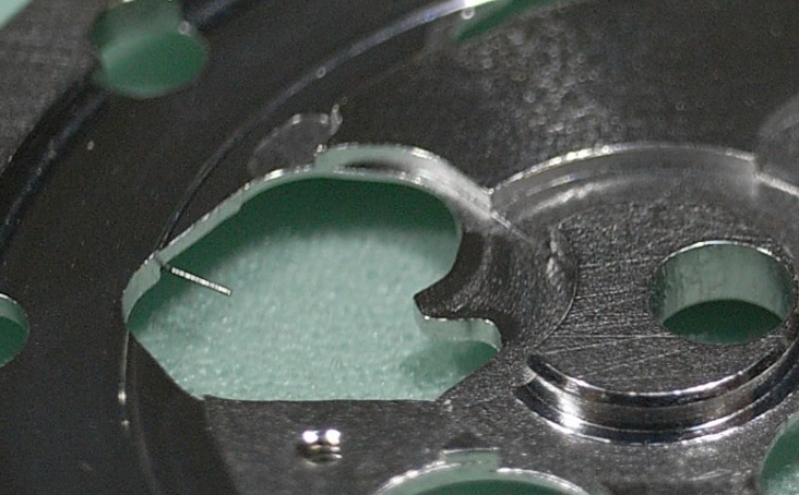
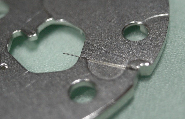
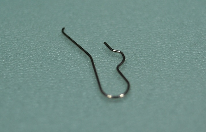
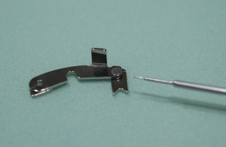
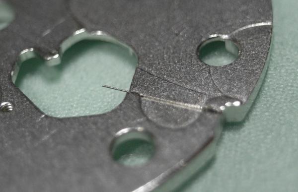
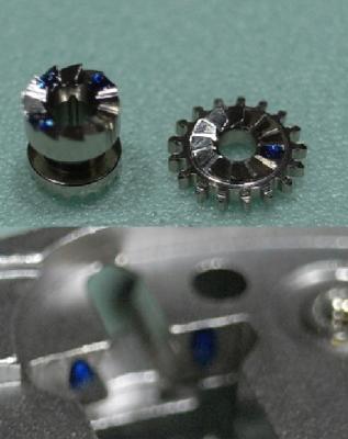
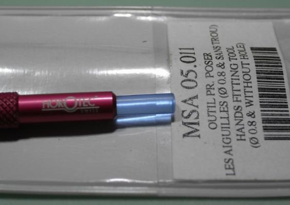
I slide it in as shown - flat side up. The end is very fine. I just used it to remove a roller. It works really well.2 points
-
Water ingress can destroy elecronic components, in some cases the damaged circuitry may not run at all or may run just a few seconds and stop, so you best make sure you have a good movement before you buy stem and crown.2 points
-
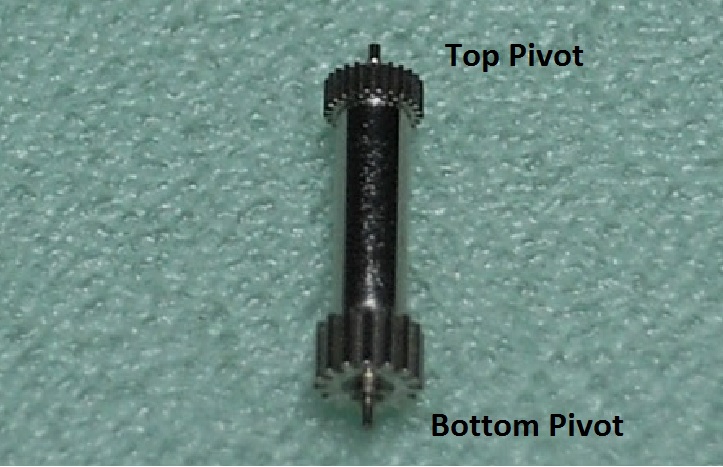
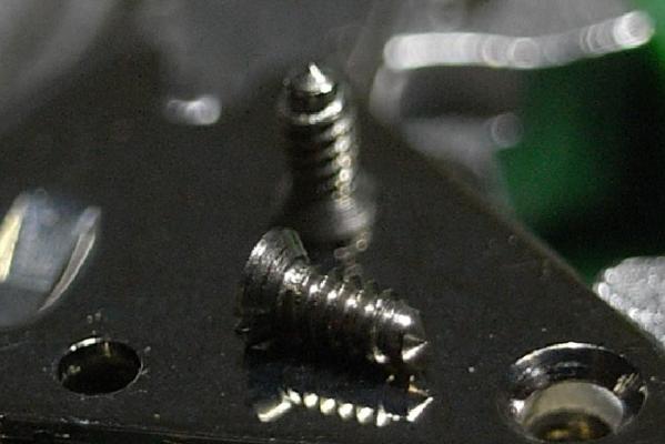
First pic has an intact pivot, second pic has a broken pivot.2 points
-
Bingo .... and thanks everyone. Soaking overnight plus a little very gentle heating with a fine soldering iron and it came loose .... it was a reverse thread as you all thought.2 points
-
Everyone has their own thoughts on wether a mainspring should be replaced or not. When you work on lots of similar movements, you get a good idea based on the stripped main spring wether it should be replaced or not. In many cases I re-use the old mainsprings, but if you see the mainspring is obviously misshapen or can see wear marks inside the opened barrel it means the spring (or in some cases the whole barrel) should be replaced. Its perfectly accepted to re-use mainsprings, but then make sure the old one is suitable. Like I said, if you work on many similar movements you know if the result is correct or not.2 points
-
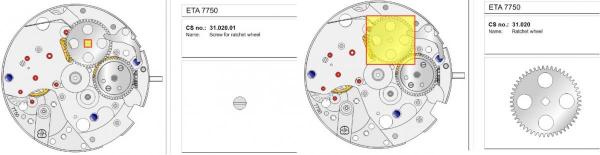
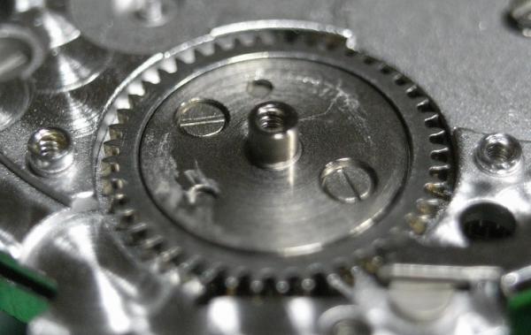
Your ratchet wheel screw doesn't appear to be rusted. Most likely it's a left hand thread. Make sure your screwdriver blade is well dressed to avoid slipping and damaging the screw slot. Apply torque in both left and right directions and feel/look for any movement. Use a gentle force initially, then increase the torque gradually. Sometimes heat is required to loosen the screw. I use a soldering iron to touch the head of the screw for a few seconds to heat it up. Good luck and don't be impatient.2 points
-
when I first came to the shop where I'm working now there were three other watchmakers. I learned from them they wouldn't even touch a watch unless they had the replacement mainspring in their hand. When I inquired I was told it was a liability reason. You'll find in most modern shops if not all modern shops they will always replace the mainspring is just what they do. But is it really necessary? If it's a modern white mainspring and it still looks like it's in decent condition. And in the watch if 24 hours later you have 200° or whatever degrees of amplitude you're supposed to have in other words it seems to be doing the job it's fine. I do find it rather amusing that Omega has a working instruction on recycling a mainspring parol. They explain how to disassemble the barrel everything is supposed to look at which is not just a mainspring. Everything has to look perfect basically. Mainspring is wiped off with a lint free cloth. Then the whole thing is reassembled. But as we have a Swatch group service center in town the watchmakers I talked to they always replace the entire mainspring and barrel obviously this memo and never made it to the service center as I'm typically working on vintage watches incoming before I service I like to pre-time. Iin order to pre-time I just need to get the watch running somewhat and I don't worry about whether the mainspring is set or not. A set mainspring will initially run the watch it just will not run the watch for 24 hours. So you have to be careful in assuming her mainspring is good when you finish servicing because unless you run the watch for 24 hours in not necessarily going to know whether the mainspring is good or not. then do I reuse mainsprings yes. As the mainsprings in pocket watches are getting harder to get if the mainspring in the watch was white it appears to be in good shape all reuse it. In other words if it does the job it stays with the watch. Then the use of blued steel Springs? For variety reasons I will use blued steel Springs like if it's a small Waltham sometimes the only way to get the hook into the barrel is you have to have original spring too much work to make anything else fit. We take blued steel Springs out of the package some of them actually look more beautiful than a moderate white spring they have a beautiful back curve they been sitting in a package for the last I don't how many years and they look better than a modern spring. Others have rusted and come out in pieces some other times they look set but if they look good there isn't any reason why you can't use them. Oh and some modern white Springs that, the package I've seen them looking set they just don't open up for a big. Is unfortunately no guarantee that your mainspring was properly manufactured in the first place even if it's white and new. then I'm not good as a hobbyist if the person doing the servicing is the owner of the watch and you're objecting to the high cost of the mainspring. It's a modern way colored mainspring and it looks fine I would just use it again. Only if it's going to be your every day watch that you really need to know what time it is and it's not making it 24 hours and you suspect the mainspring then you get stuck changing it otherwise I wouldn't worry about.2 points
-
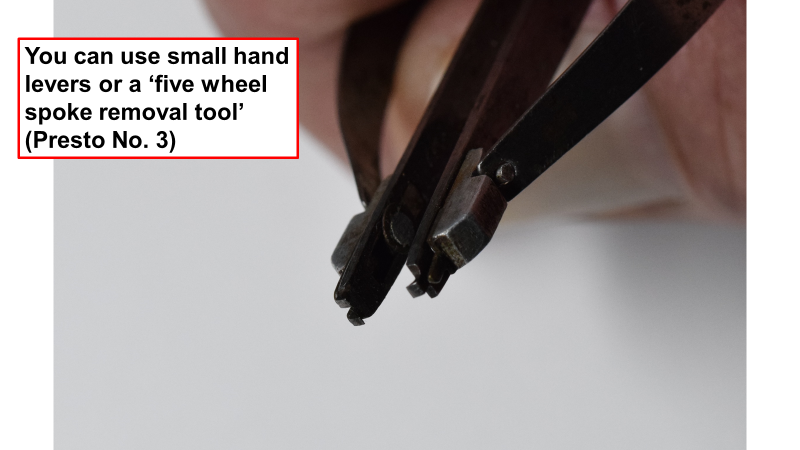
Presto tool for 5-spoke wheels UMF 242 points
-
So i guess the thing to do here would be to find out what the inner barrel diameters of these movements are to know what size mainspring winders you are getting before you order them. To see if any fit the watches you are working on or intend to work on. Or work specifically on these watch movements. If they are close undersize then they may fit other movements. A word of warning though i wound a spring into a winder that was a little tight. It went in but there wasnt enough room to unhook the winder arbor. The spring finished up like an overstretched slinky and the pin of the winder got damaged. This is one reason i refit the spring by hand lol. Also avoid any winders that dont have a steel arbor pin.1 point
-
And the 8200 if for the Miyota/Citizen movement but will also do some Seiko, eg the 7009 etc1 point
-
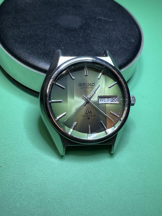
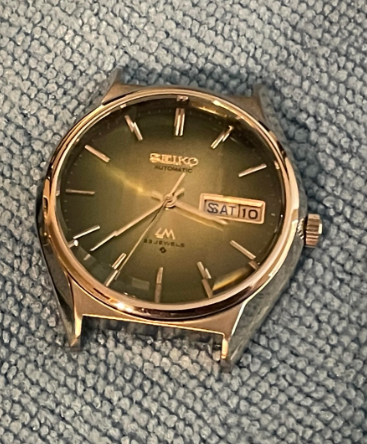
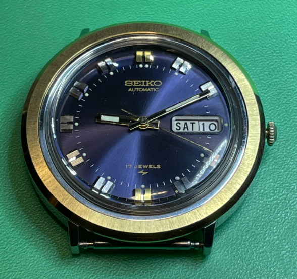
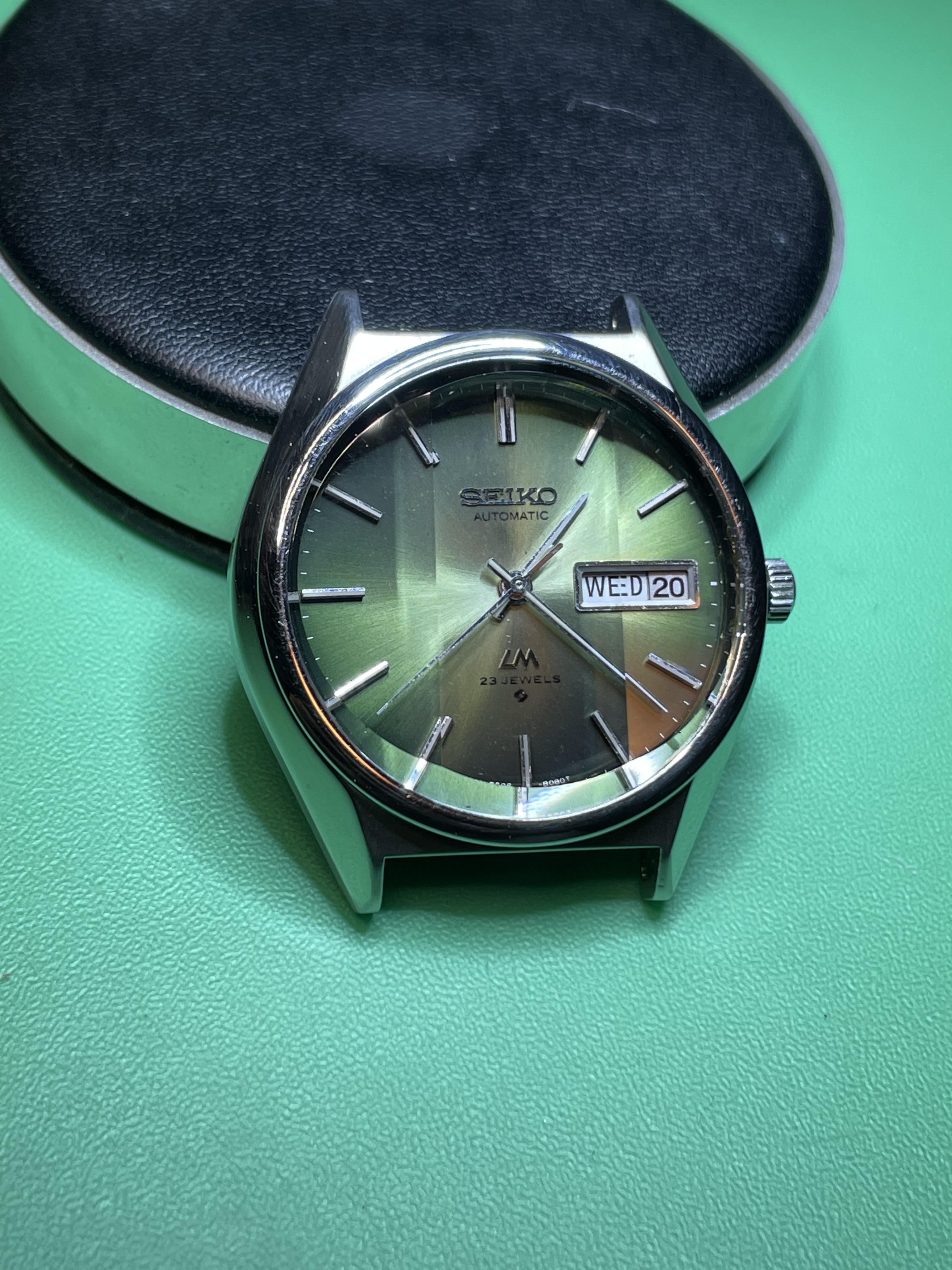
The final parts for these watches arrived on Thursday and today. I documented the adventure I had with the Lord Matic crystal yesterday in another thread. After 4 weeks of shipping time, the bezel for the 1974 Seiko arrived today. I so happy to see these running. I'll order some straps for these this weekend, and by the time I return from my work trip next week, hopefully they'll have arrived. The 1972 Seiko Lord Matic: The 1974 Seiko 7006-8190R There was some surface spots on the bezel, which I was able to remove by using some glass cleaner and a microfiber cloth. It took quite a bit of scrubbing, but I was able to clean it up pretty well without damaging any of the plating. There is only a hint of a spot visible around the 10 o'clock position on the bezel. Aside from the few marks on the dial that I could not remove with Rodico, this thing is in great shape now. Now that I'm looking at the photo I realized that I never pushed the crown back in after setting the time when I took the photo. It's bugging me now, but I don't want to go and take another picture!
 1 point
 -
I'm no expert Ross but as far as i know the number relates to popular movements. Ie. 7750 would be the Valjoux 7750. 2892 is Eta, 8500 i think is an Omega.1 point
-
Good call. Yep you may have nipped it up a bit tighter on your first attempts. I snapped a rachet wheel screw on one of my first repairs. I did know but completely forgot, so used to standard threads from my job. I've screwed that way for years ,( said the actress to the bishop ).1 point
-
Glad you got it sorted mate. Without knowing its left hand threaded HectorLooi's suggestions to sensitively feel for freeing movement is the ideal practice for proceeding with caution.1 point
-
Hm, is the friction spring fitted correctly with slight tension: https://watchguy.co.uk/cgi-bin/media?image=P1090695.JPG&email=&wat_id=35151 point
-
As a home hobbyist, rather than buy the 5 and 6 spoke tools, I bought the Bergeon 6016 tool. Useful for removing wheels, hands, rollers etc
 1 point
 -
If you do not have the correct tool my advice would be leave it alone, you could easily damage the wheel or break the pivot.1 point
-
That 5 spoke Presto tool has been out of stock for months now. It shows stock coming soon, then the date shifts again lol. I’ve been using @Jonmethod above, but I would really prefer to use the Presto tool. I have a few very expensive watches coming in - hopefully that Presto tool is in stock soon.1 point
-
Thank you! It is gratifying to get positive feedback from the members on here. I'm guessing that 99% of everyone on here has more experience than I do at this point, so I appreciate the feedback!1 point
-
I love the description on Cousin’s website. A “Jewel Picker Upper”1 point
-
Wow, nice work on getting that extremely rare crystal to fit and the polishing work on your friend’s watch! I must agree with you, I also really enjoy the case finishing side of things on watches. I haven’t posted some of my latest projects here - I’ve been lazy.1 point
-
Yes. These are vintage. But they do show up on eBay occasionally.1 point
-
Any screw, especially on vintage watches have a habit of being really tight every now and then. I know I mentioned a left handed thread, but I've only read about it and have never come across one on a ratchet screw myself, although I have come across left handed dial screws, which even had three cuts in the heads to denote that fact. No reason to have them as a left handed thread either, buy hey... I would have put it in penetrating oil as well. If you do manage to grip the ratchet wheel, it would be safer than holding back the barrel teeth, as they are likely to break very easily, although depending on how much pressure you have to put on the screw. you might damage the teeth of the ratchet wheel if you're not careful. I would use a 3 mm acrylic stick fashioned on the end like a screwdriver blade, so you can jam it between the bridge and the ratchet wheel teeth. If anything will give first it will be the acrylic stick, rather the a tooth. The thicker the end of the stick is the more resistance before breaking, so experiment and start with a low breaking point and work up. I use them all the time to pry off bridges and hold them down, as well as keeping the ratchet wheel still whilst screwing it down, as they don't flake like some pegwood1 point
-
I dont understand how the top of the jewel and the cap jewel can be cleaned properly if it is left in place. Apart from the jewel hole this area is encapsulated, surely dirt could become trapped inside. Or at the very least a residue left behind from the cleaner and any dirt present to then contaminate the new lubricant. From an enthusiasts point of view using a basic cleaning machine.1 point
-
I agree they are fiddly, but I wouldn't leave them in place to clean, as they aren't going to be cleaned properly, then lubricant is added to a dirty cap jewel. Learning how to remove and replace these springs isn't that hard with the correct tool. I also use a honed down oiler to push the oil through the oil sink.1 point
-
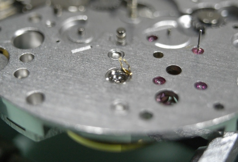
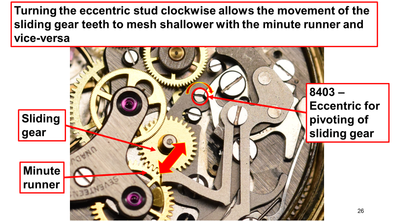
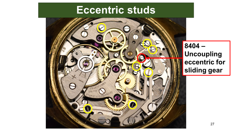
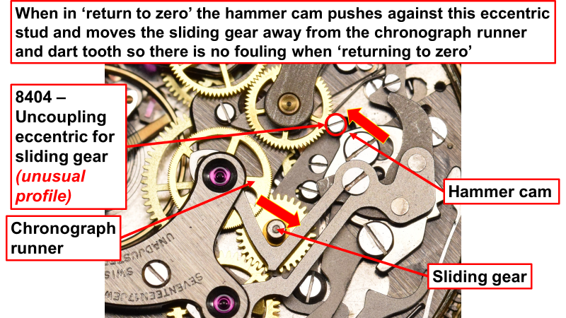
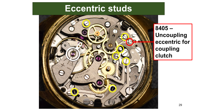
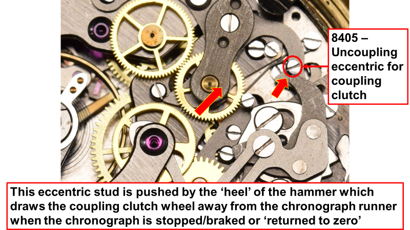
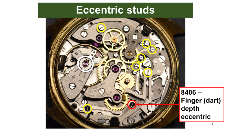
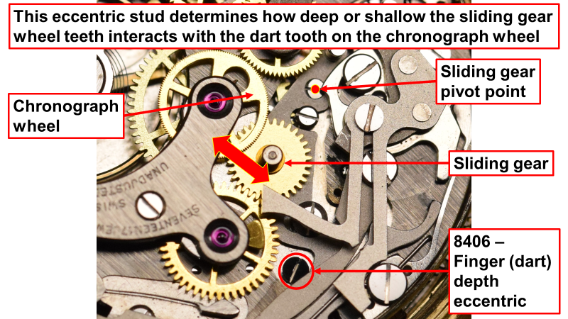
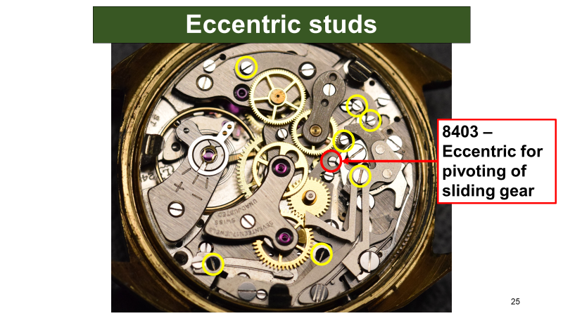
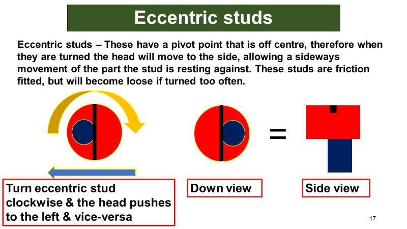
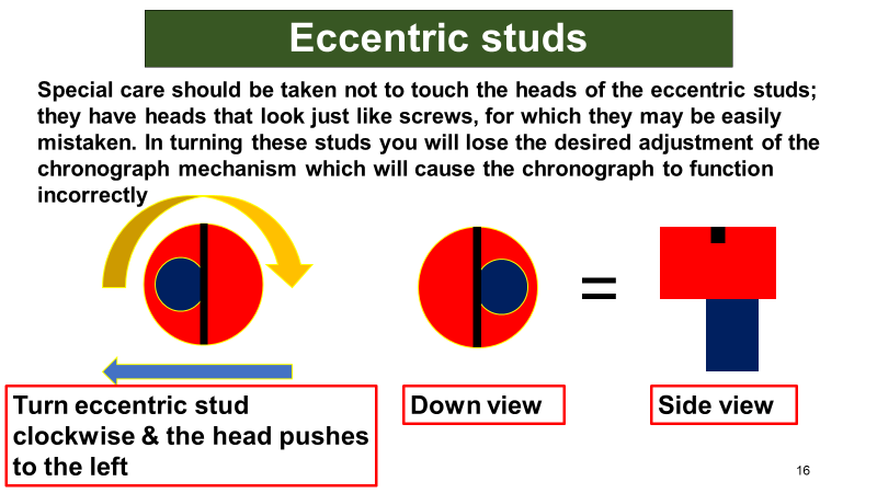
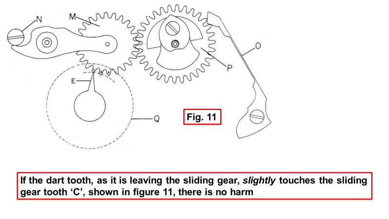
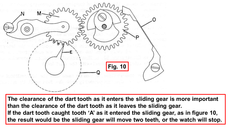
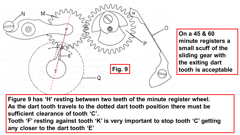
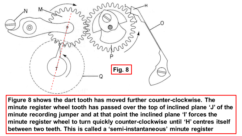
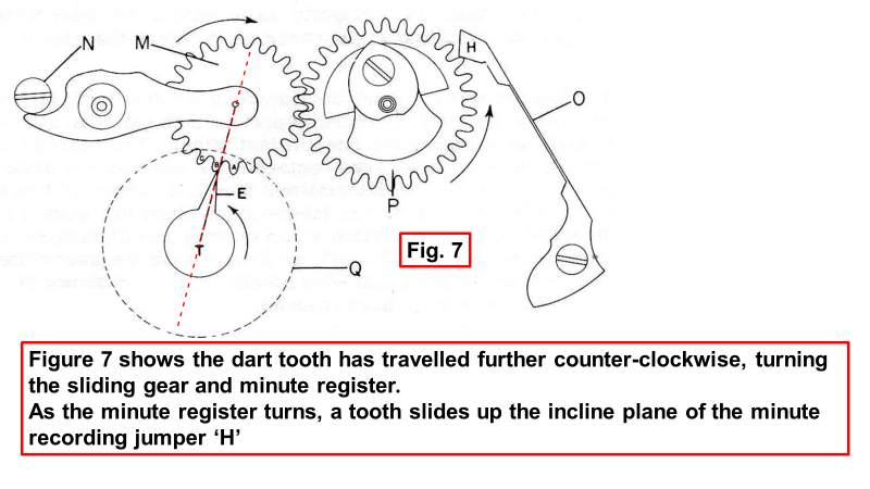
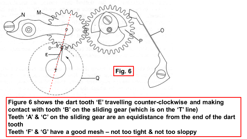
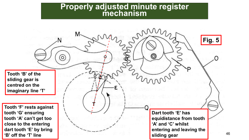
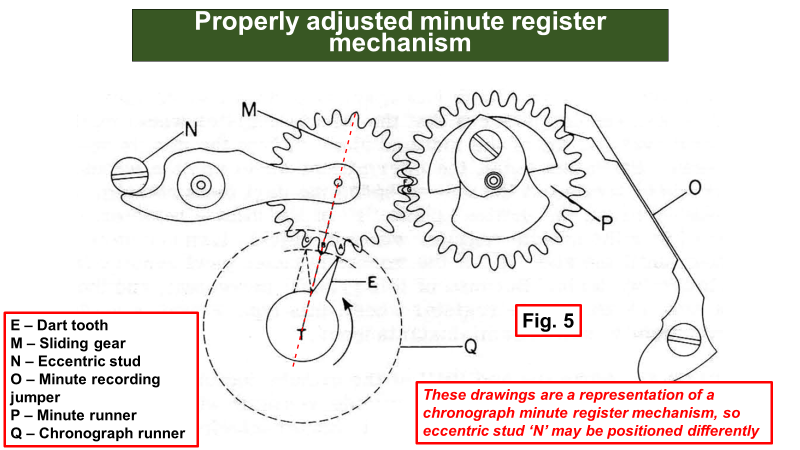
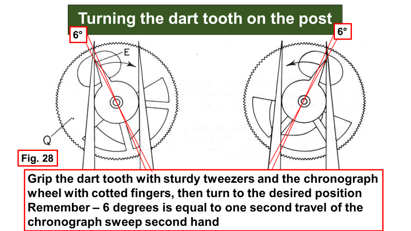
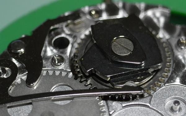
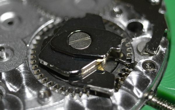
This is slightly different from the Landeron 51, as this is a Landeron 248, so the eccentric studs might be different, but the principles are the same. Before thinking about moving the dart finger, I would ensure the minute register mechanism is set up properly. The slides will help understand the theory as well as the practical application. You have to understand how this works before adjusting anything, as turning an eccentric stud and not knowing what the result will be is asking for problems! These are just a few slides from one of the lessons. There are many other ways to adjust the chronograph work that aren't in these few I have posted, as there are over 300 slides in the Landeron 248 lessons I wrote with the aid of the Ensemble-o-graf drawings. They are a great aid to understand chronographs. The position of the dart finger is incorrect in the photo you posted. It needs to be on the other side of that tooth of the sliding gear. Here's a picture of how the dart tooth should be almost touching the sliding gear tooth, so it travels almost 360 degrees before turning the sliding gear and minute register. If you set the minute register mechanism properly, it may change the position of the teeth on the sliding gear so the dart finger is on the correct side when starting the chronograph, or you may find that you need to turn the dart tooth, as @praezissuggested.
.png.f6ae2040631614914c4a2b30c83ab193.png)
 1 point
 -
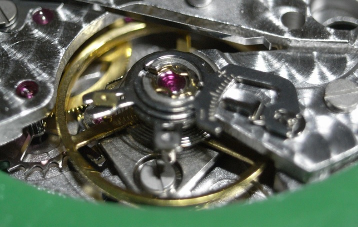
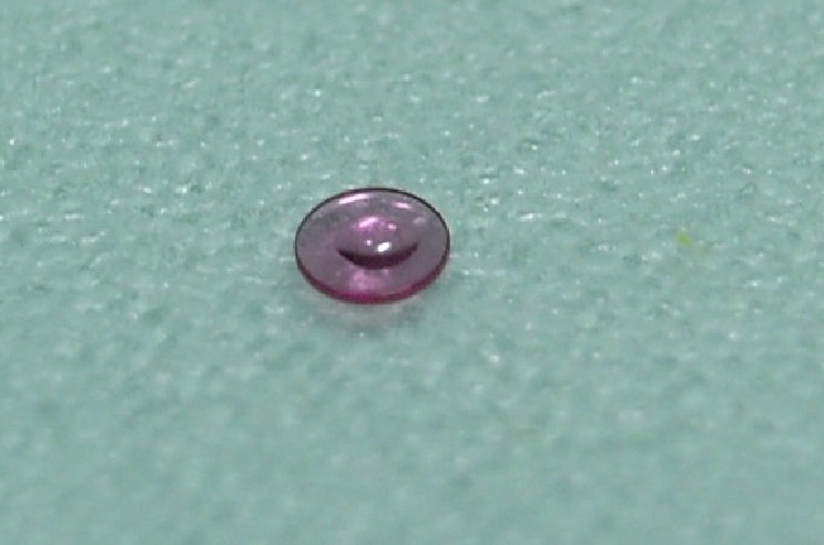
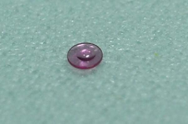
A good way to find if the fluid you are cleaning with is contaminated is put a drop on a piece of glass and see if any residue is left after it has evaporated. I clean my balance and hairspring whilst it is attached to the mainplate using L and R '#111 Ultrasonic watch cleaning solution' then rinse with L and R '#3 watch rinsing solution'. I'll even give them a rinse in 99.99% IPA if needed, as putting it through 'one dip' just doesn't cut it in my experience. If you use the correct cleaner and rinse after demagnetising, then you won't have these problems with a sticky hairspring. The rinse is critical, otherwise you are leaving residue of the cleaner on the hairspring, even if you can't see it. Also a good demagnetiser is important, not one of those Micky Mouse small blue things. They are no good to man nor beast! I use an Eclipse 955 like this: https://www.zoro.co.uk/shop/hand-tools/magnetiser-and-demagnetiser-devices/da955-demagnetiser-single-type-da/p/ZT1002385X?adid=515998013892&dev=c&net=g&pos=&trckid=XEtNjG2p&utm_medium=ps_cpc&utm_source=google&utm_campaign=ps-|-products-|-brands-with-_e_-|-%231&utm_term=da955&utm_content=zt1002385x&mkwid=-dc&pcrid=515998013892&pkw=da955&pmt=p&prodid=&slid=&pgrid={groupid}&ptaid=kwd-384916686616&gclid=Cj0KCQjwyOuYBhCGARIsAIdGQRNNxkN-bCupjy7Uhql_3vxvQ_50ZPZH-YirvSX6zsjWRLFBdNklw3AaAizvEALw_wcB They're expensive new, but you find them on eBay now and then for a good price. I picked one up for £30 a few years ago and it's amazing! You may think it's too powerful for hairsprings, but that's not the case and have never damaged one demagnetising it. You'll never wonder if you demagnetised properly again using this bad boy... BTW, if the balance staff is sitting in the jewel in the pic you showed after cleaning, then the bunching up of the hairspring coils is because the endcurve is badly formed and out of shape. You can see that very clearly. The endcurve should look like this....
.thumb.JPG.b64e4c4aedf8785af9ce6a3614cc8011.JPG) 1 point
1 point -
1 point
-
Woohoo. Thank god, i was about to crack up. Why you've knocked a thou of a mil off his length is beyond me shane. As a fact, men would prefer NOT to have anything knocked off their length.1 point
-
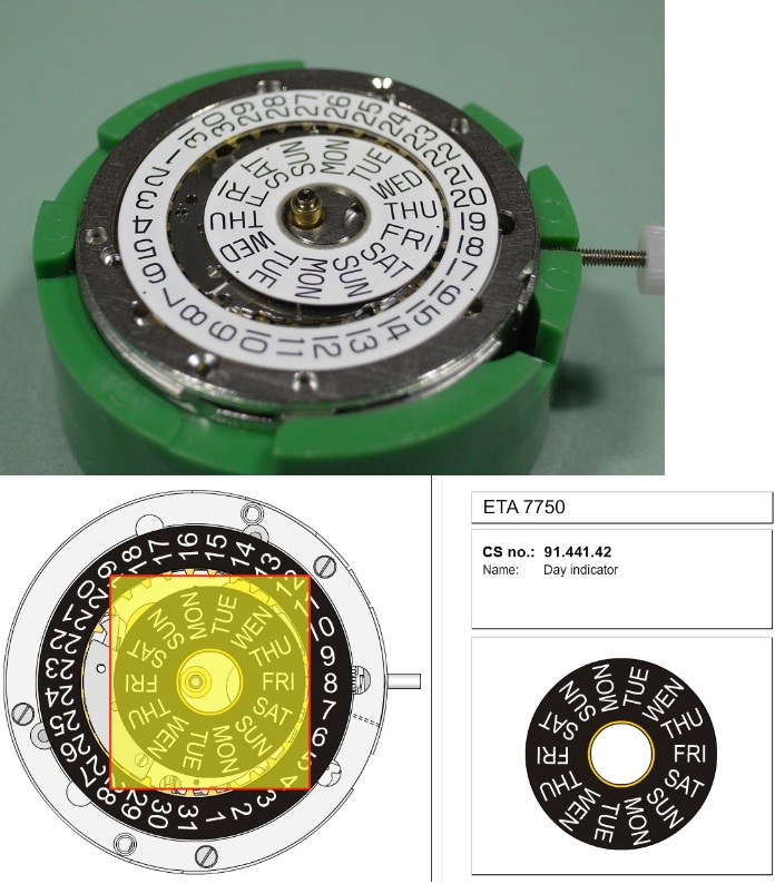
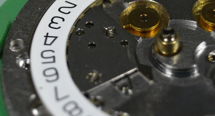
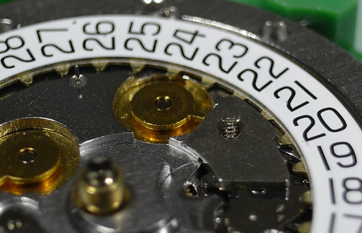
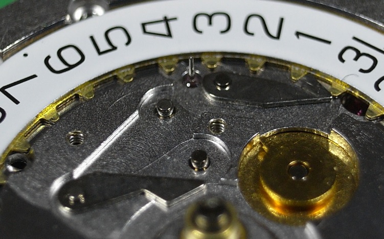
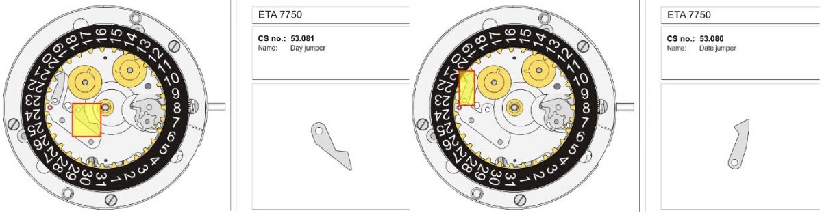
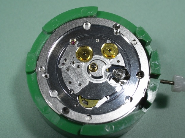
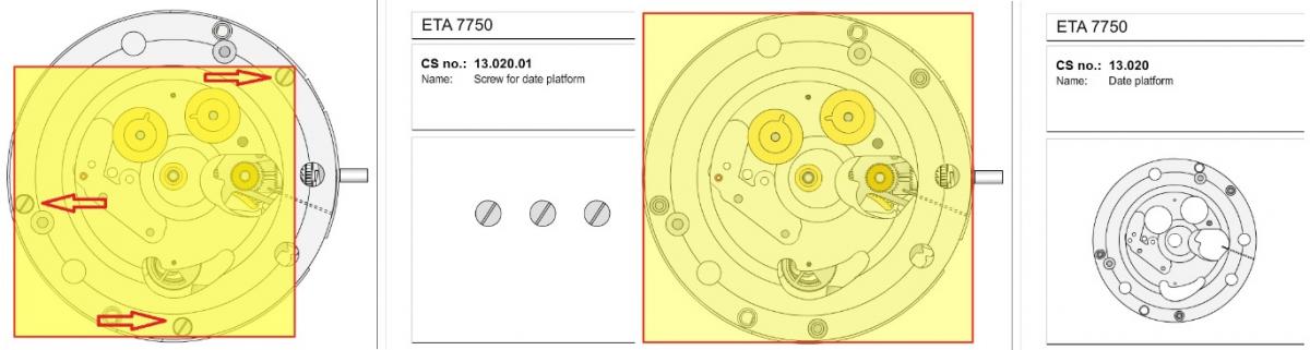
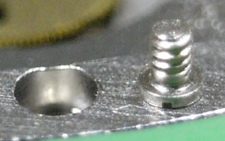
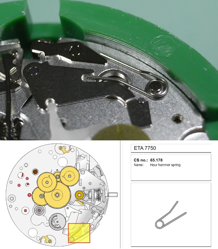
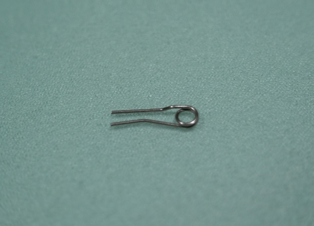
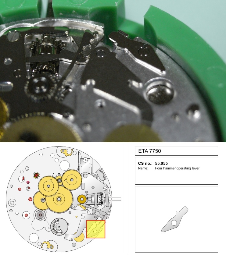
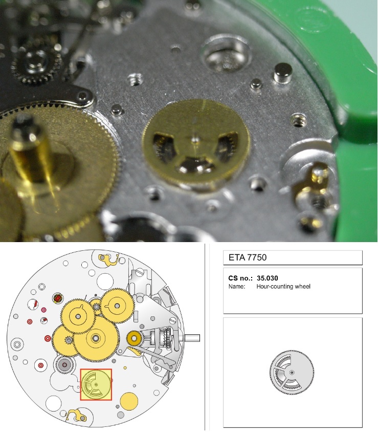
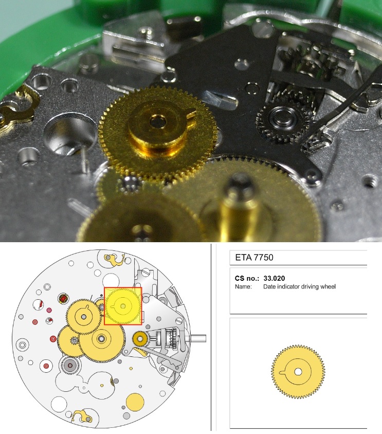
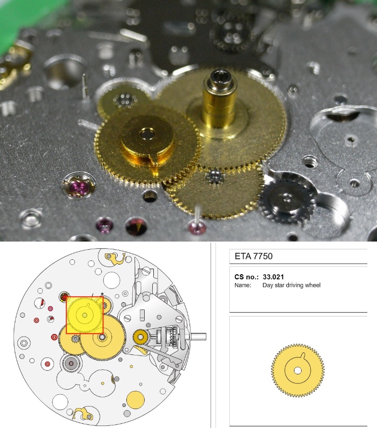
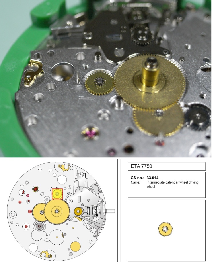
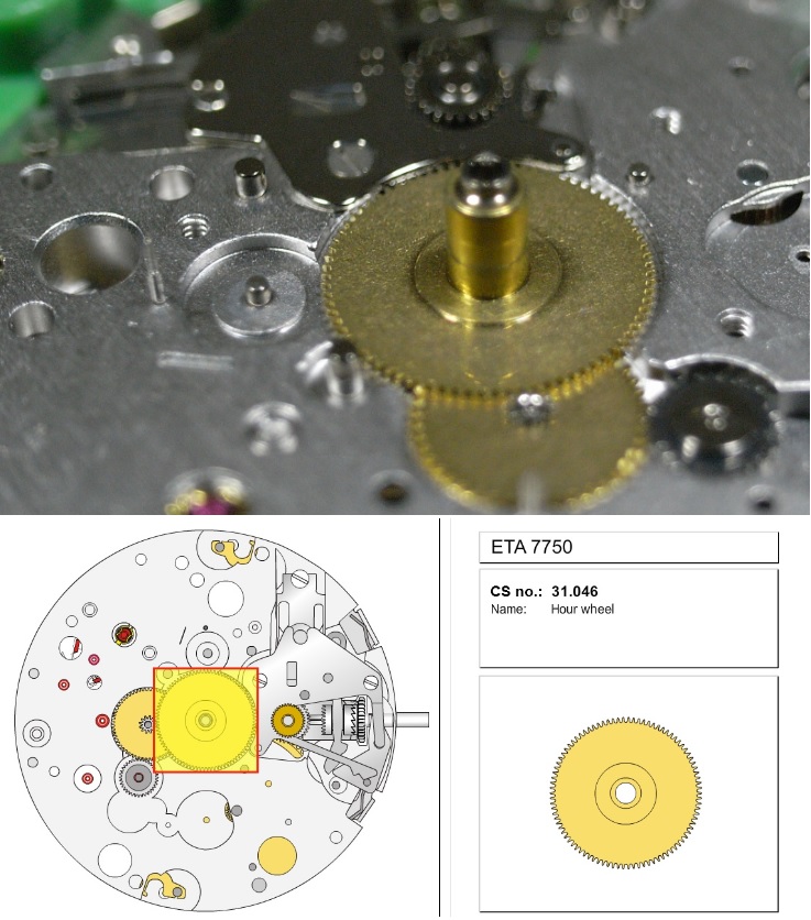
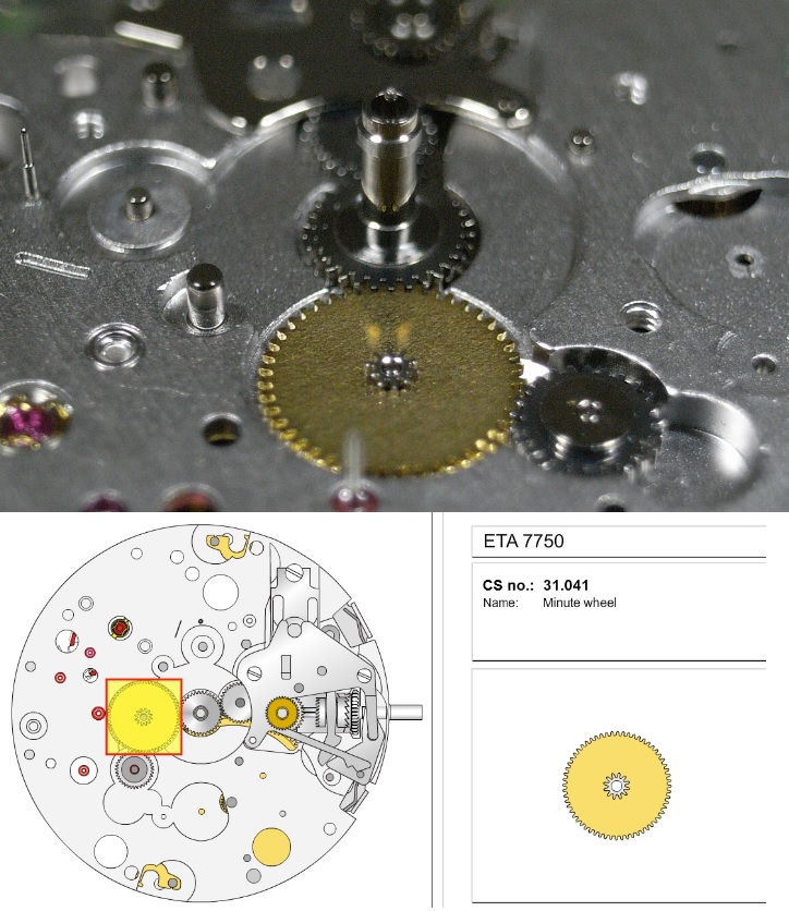
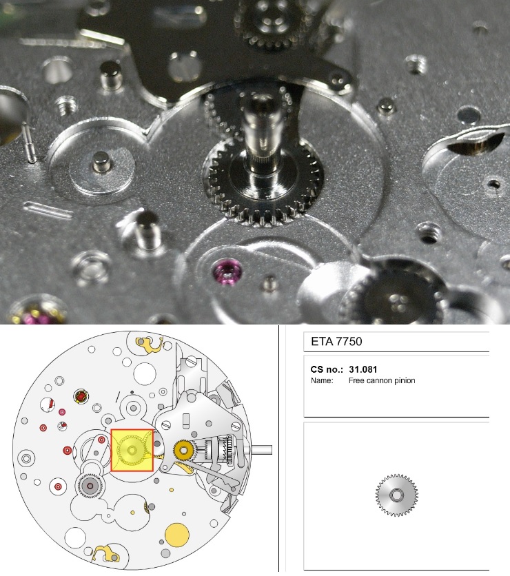
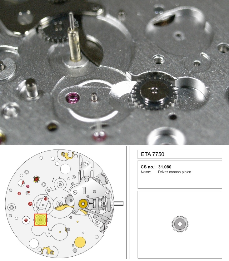
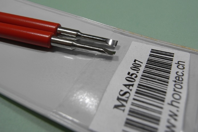
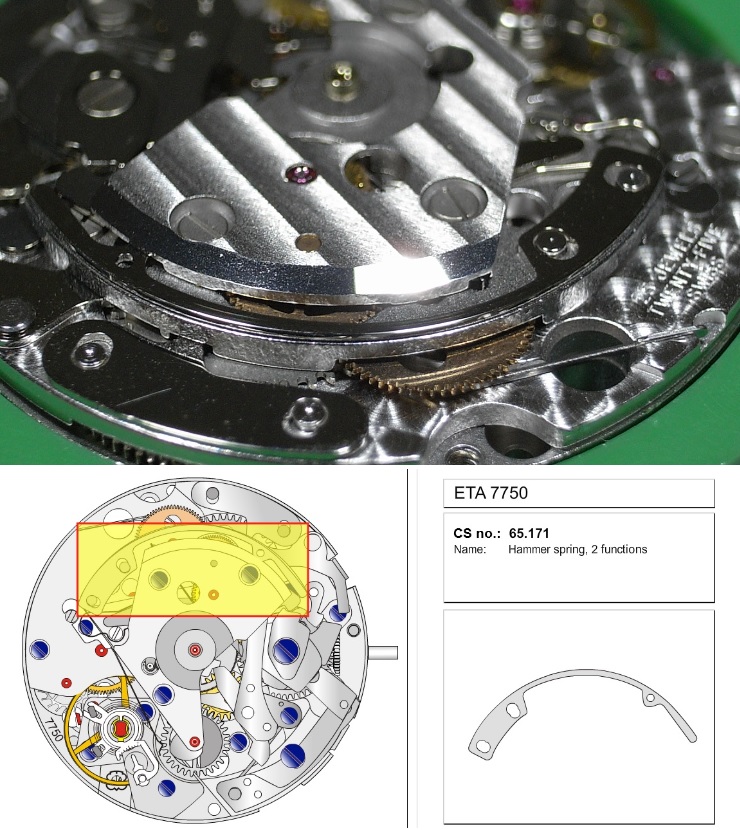
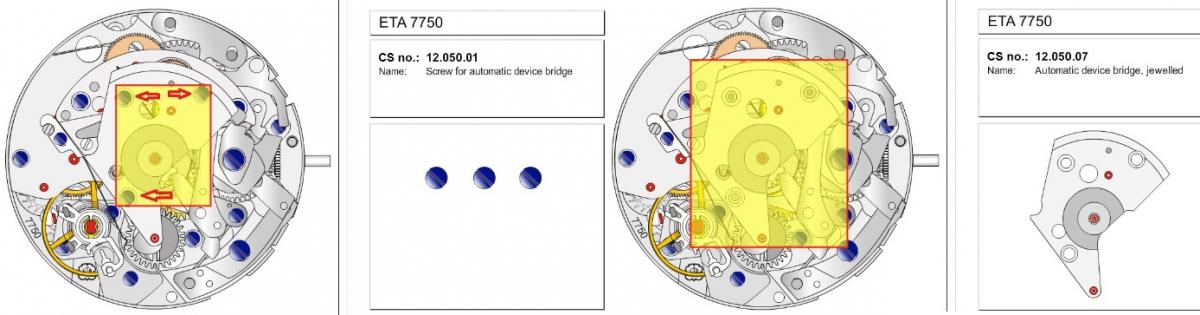
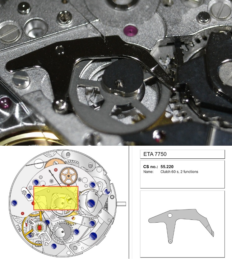
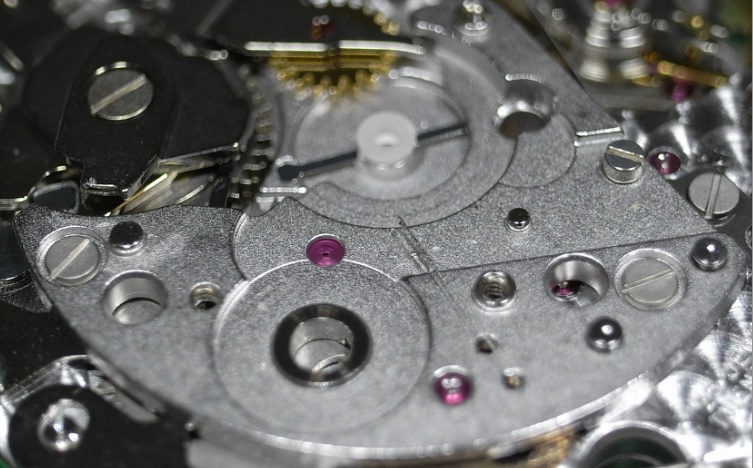
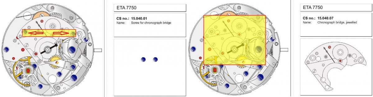
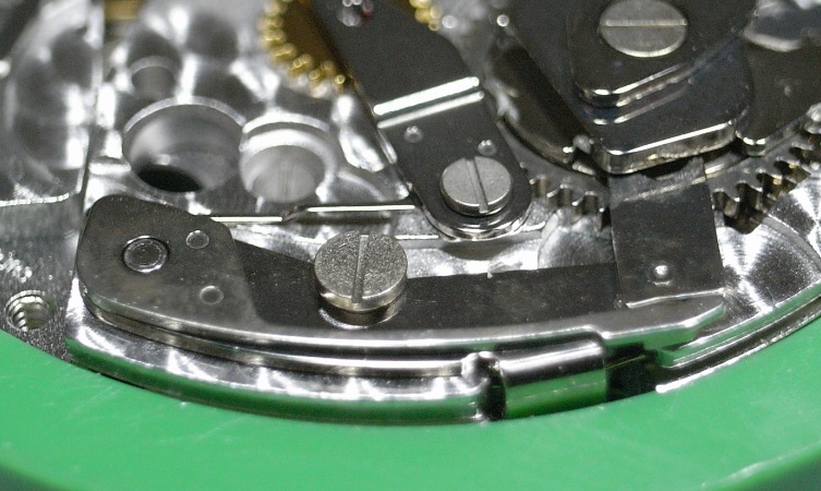
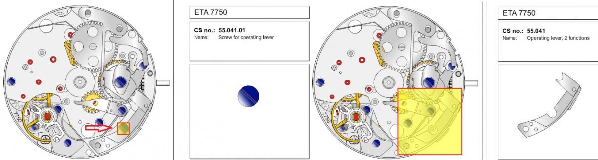
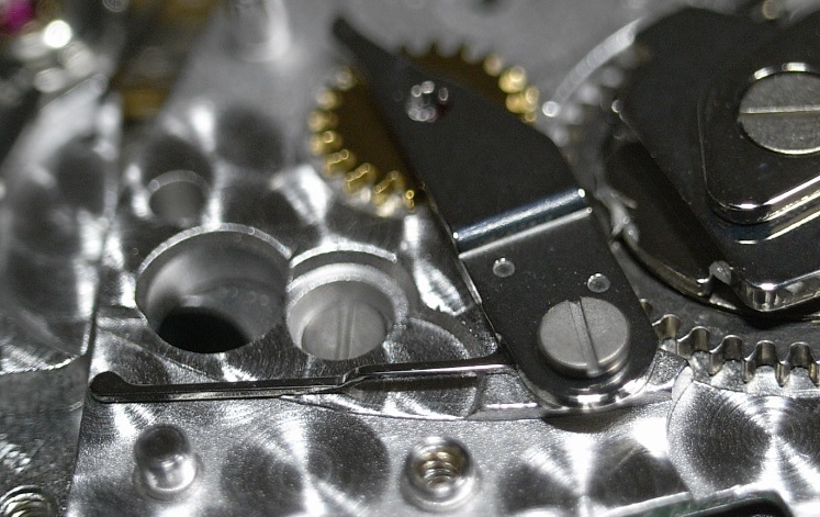
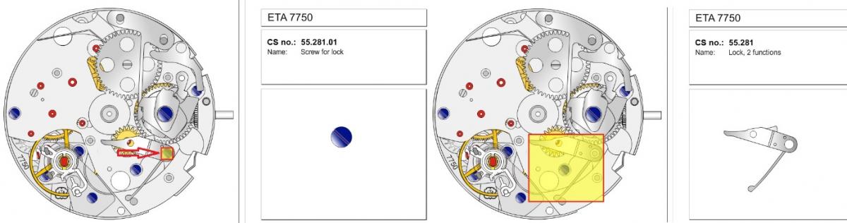
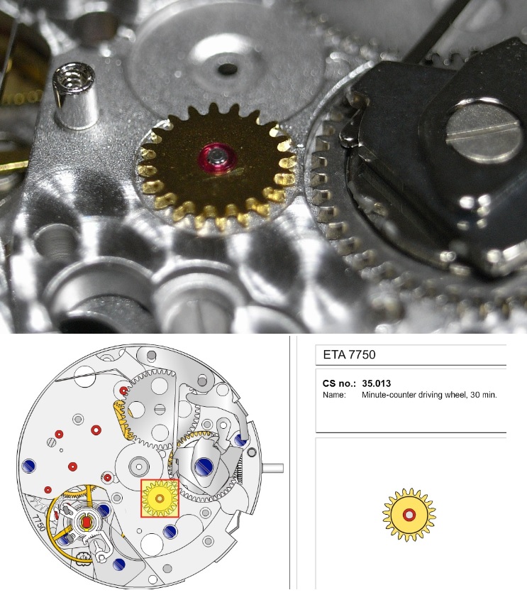
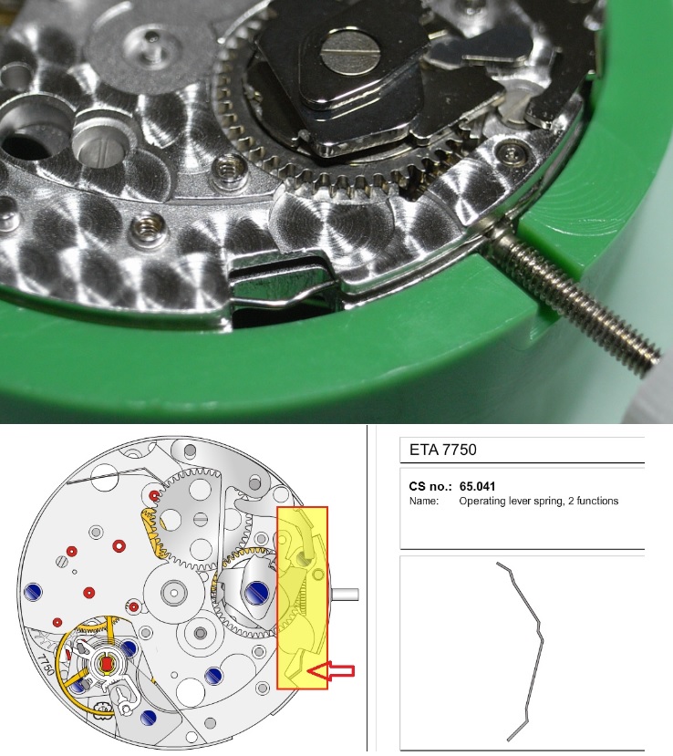
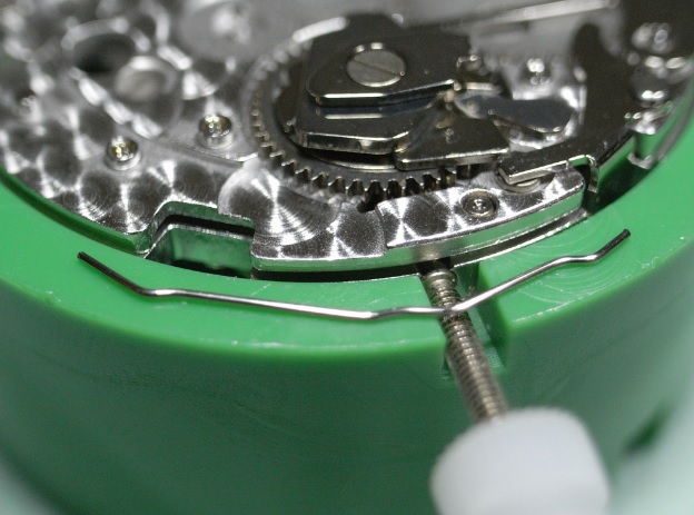
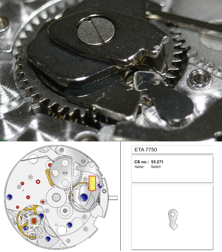
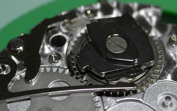
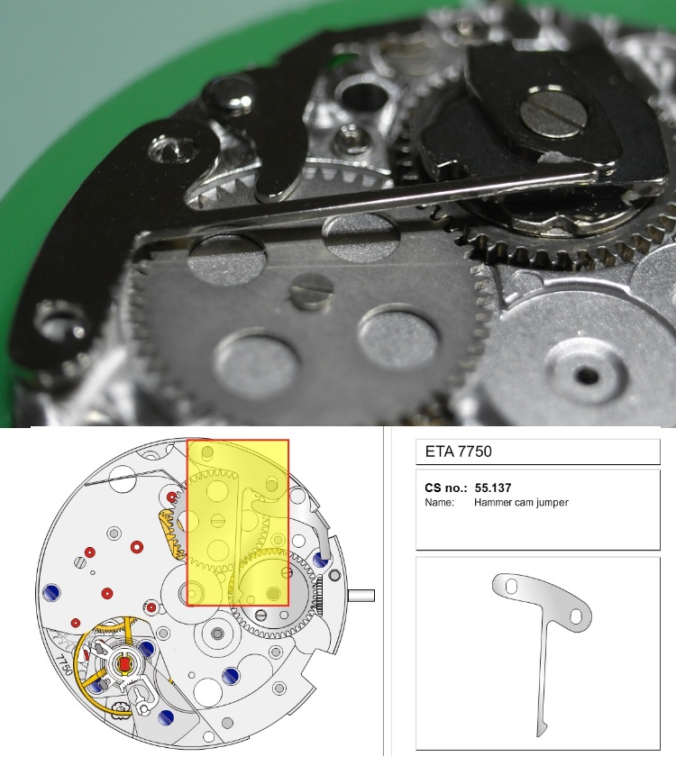
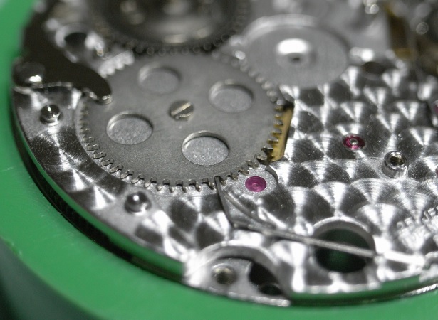
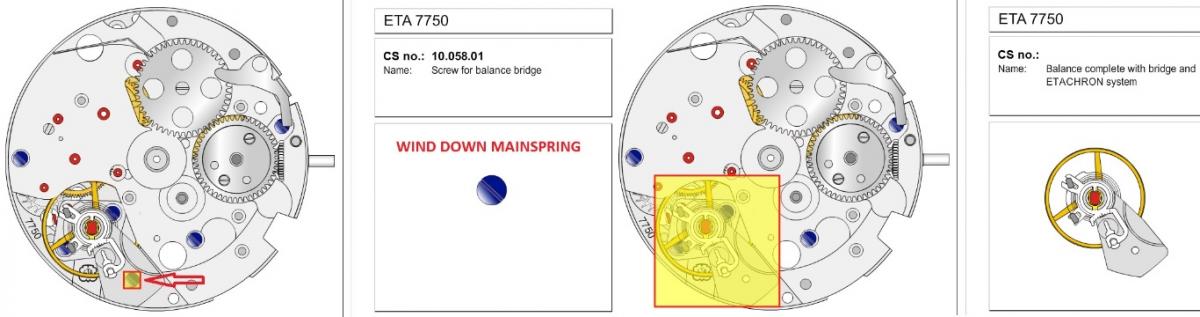
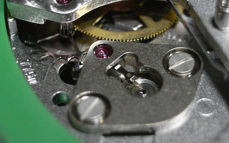
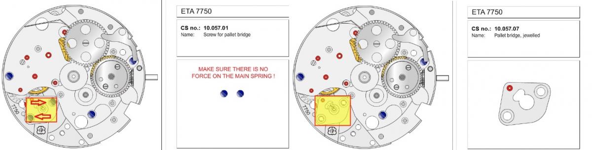
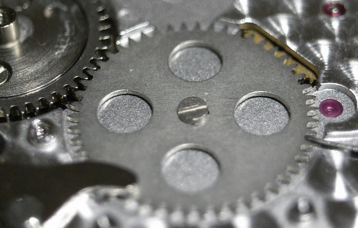
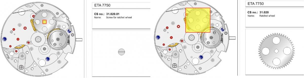
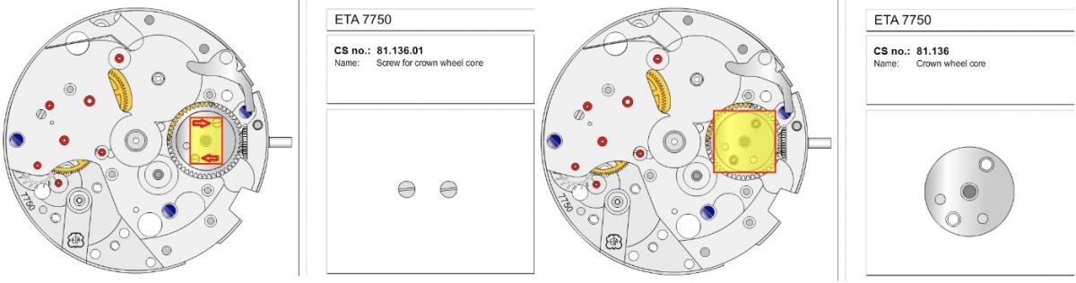
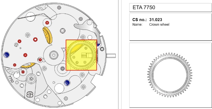
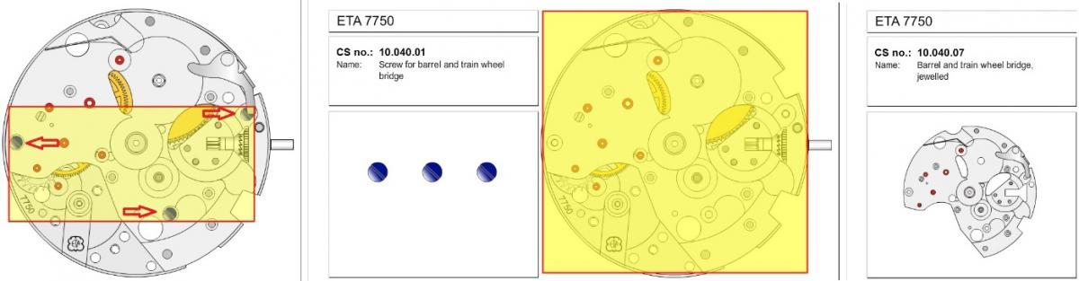
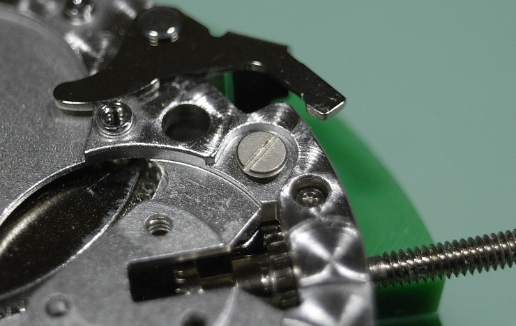
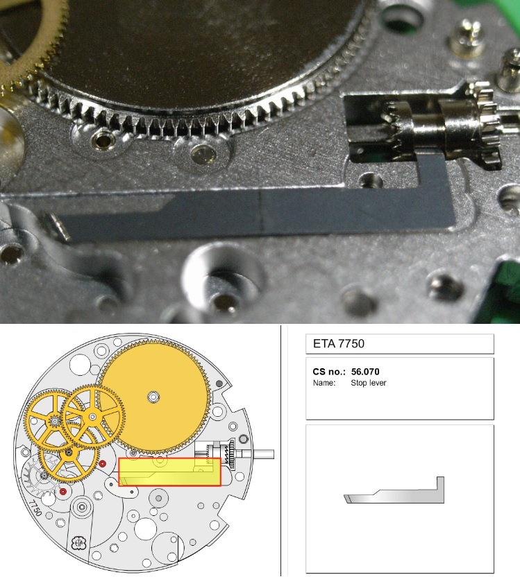
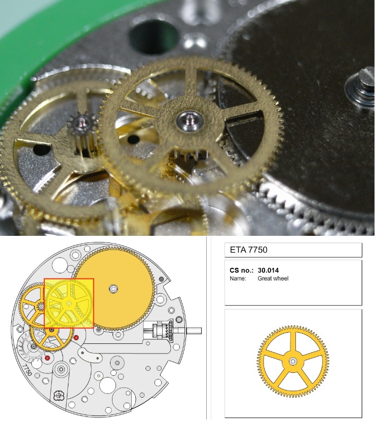
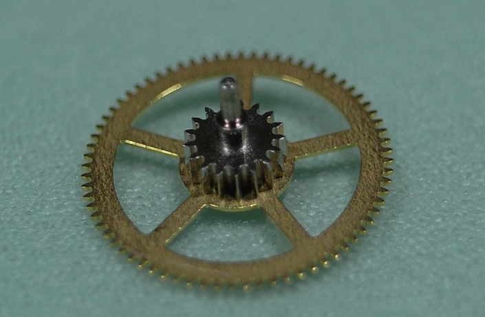
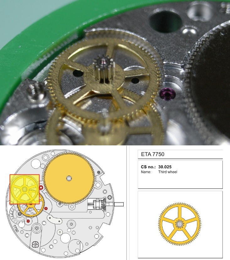
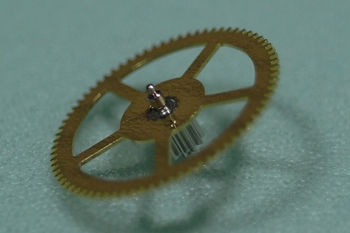
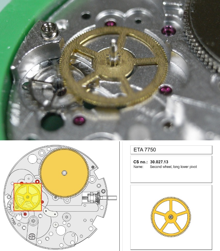
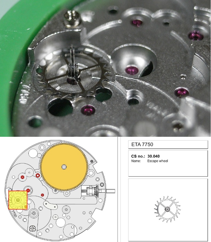
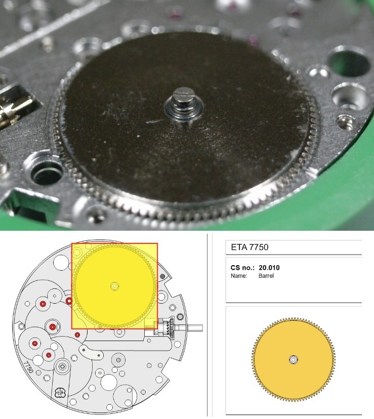
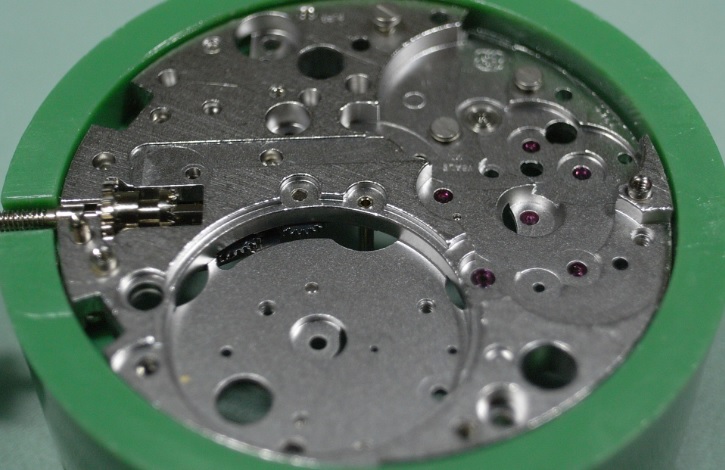
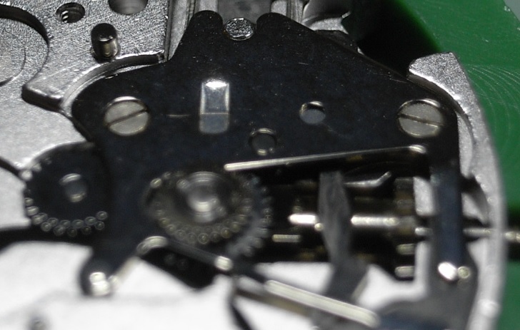
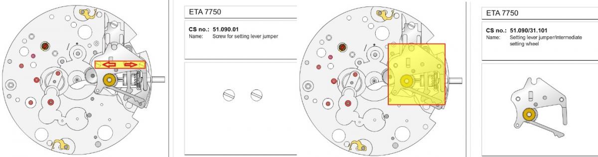
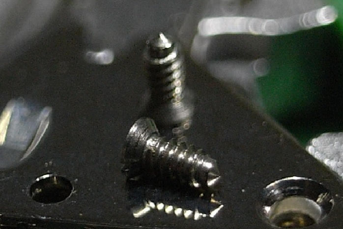
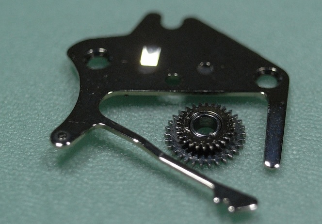
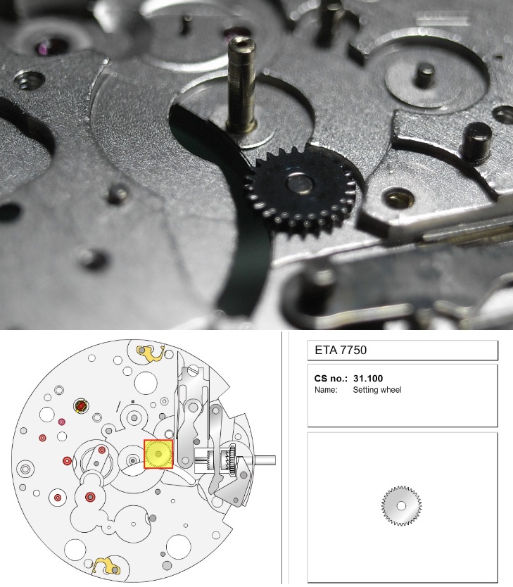
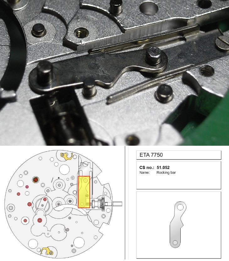
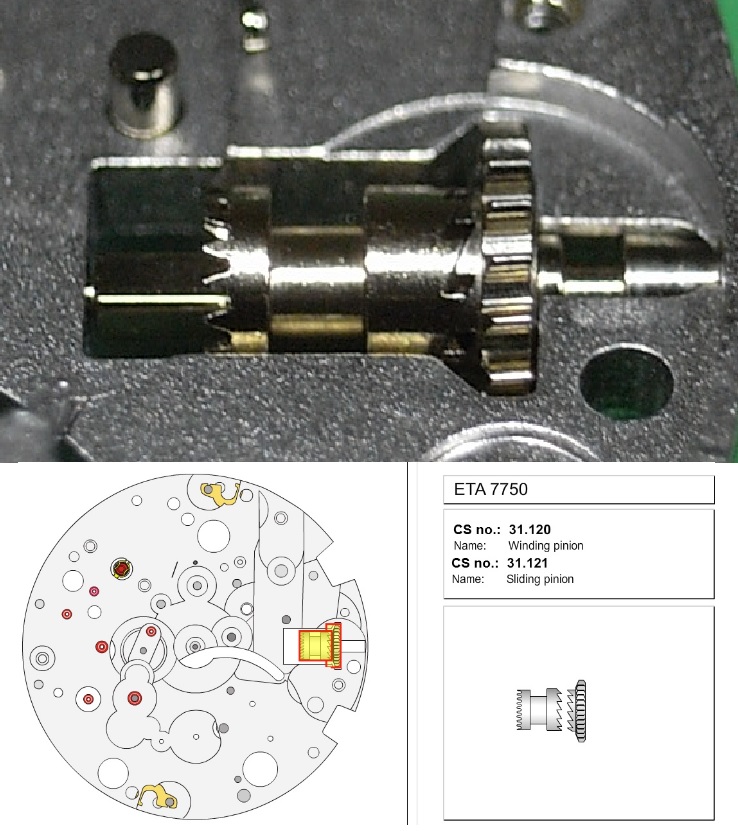
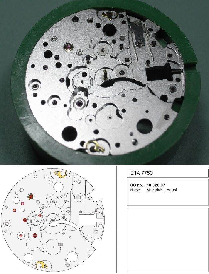
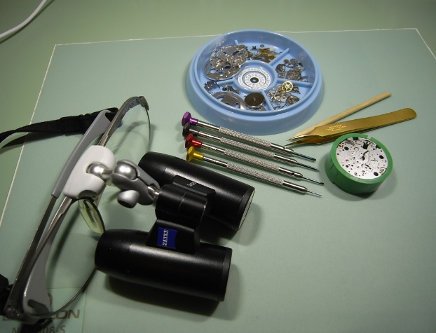
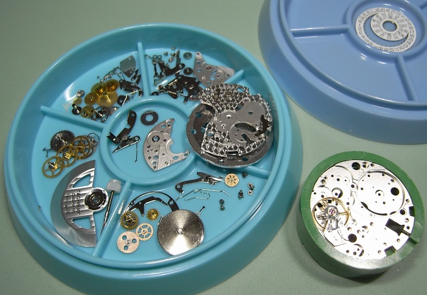
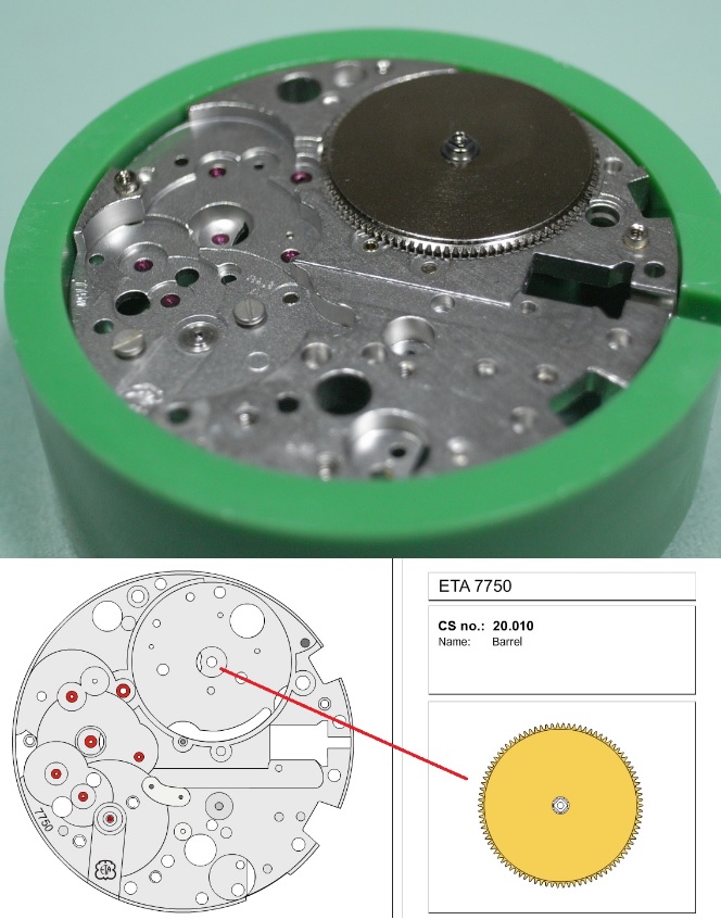
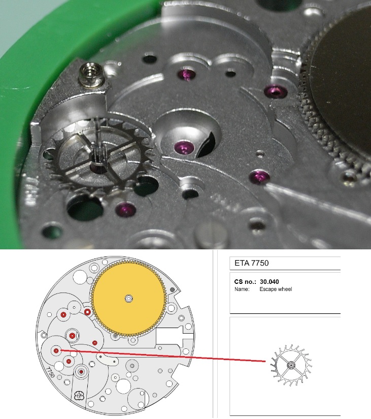
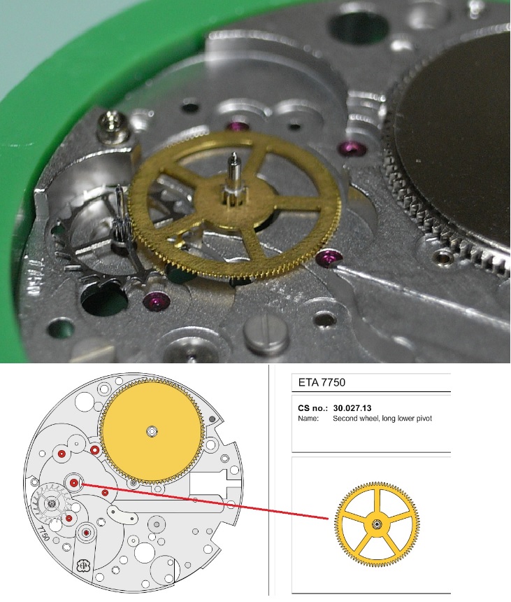
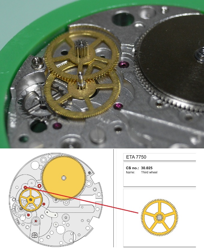
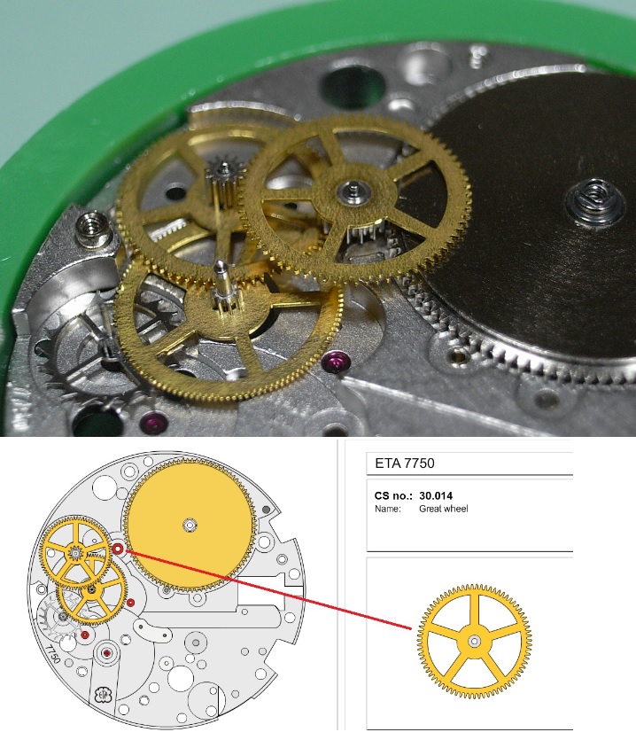
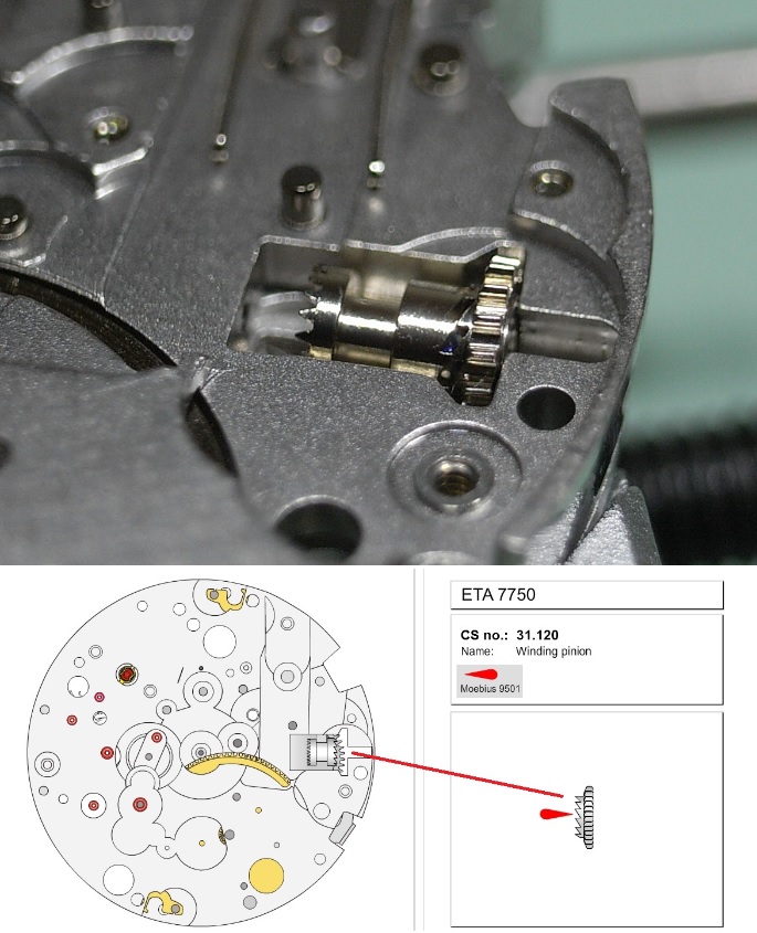
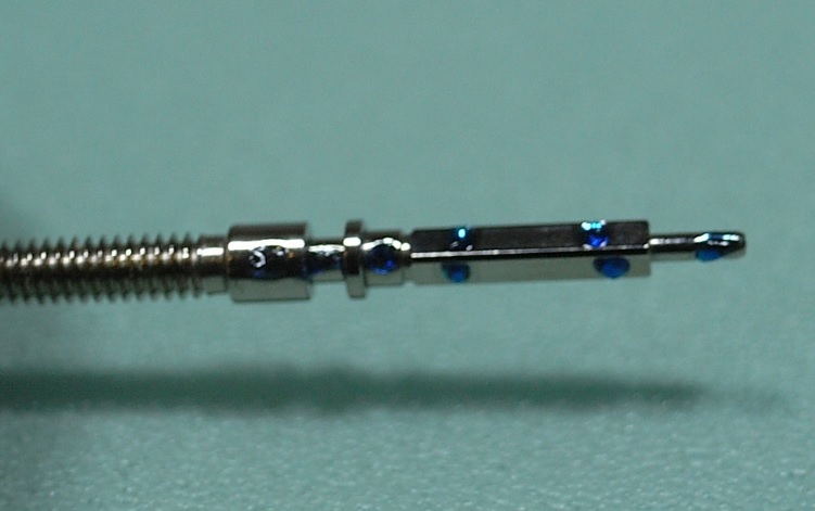
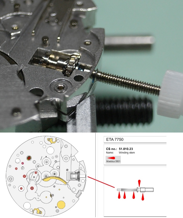
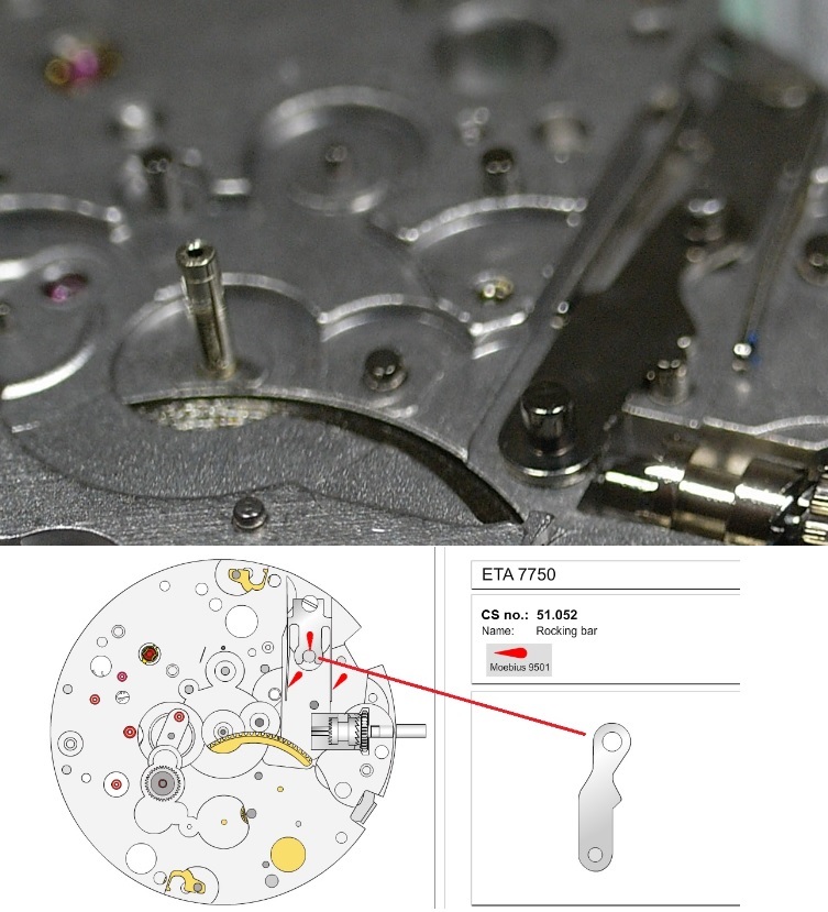
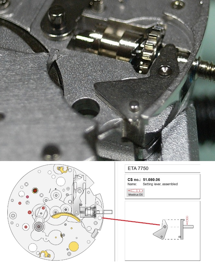
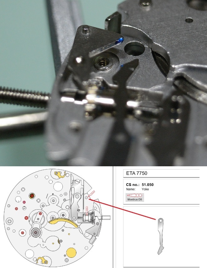
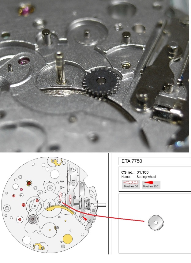
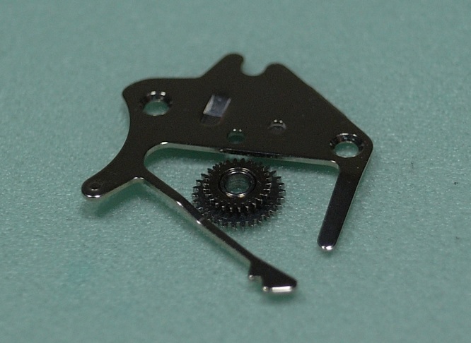
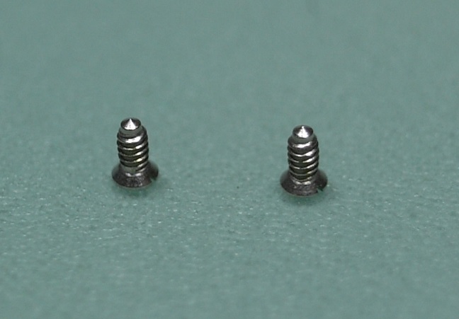
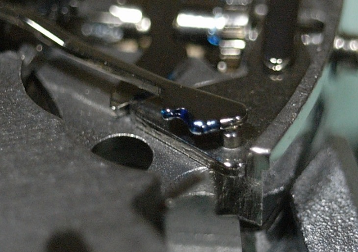
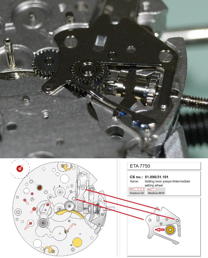
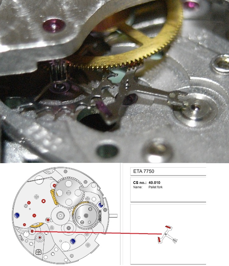
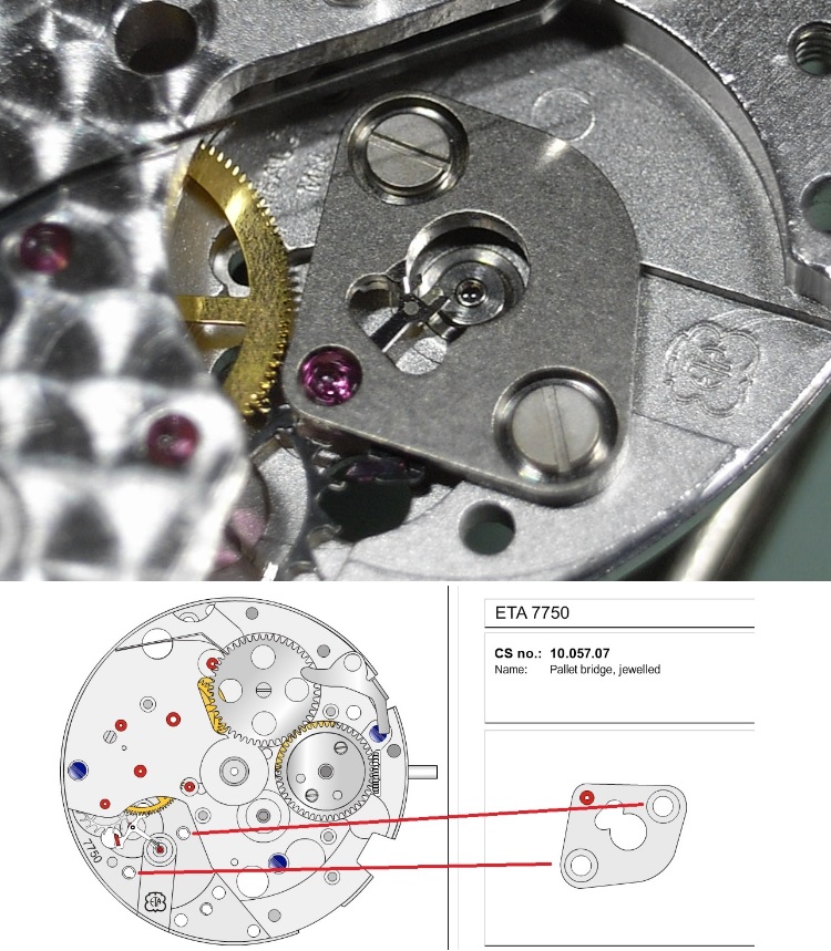
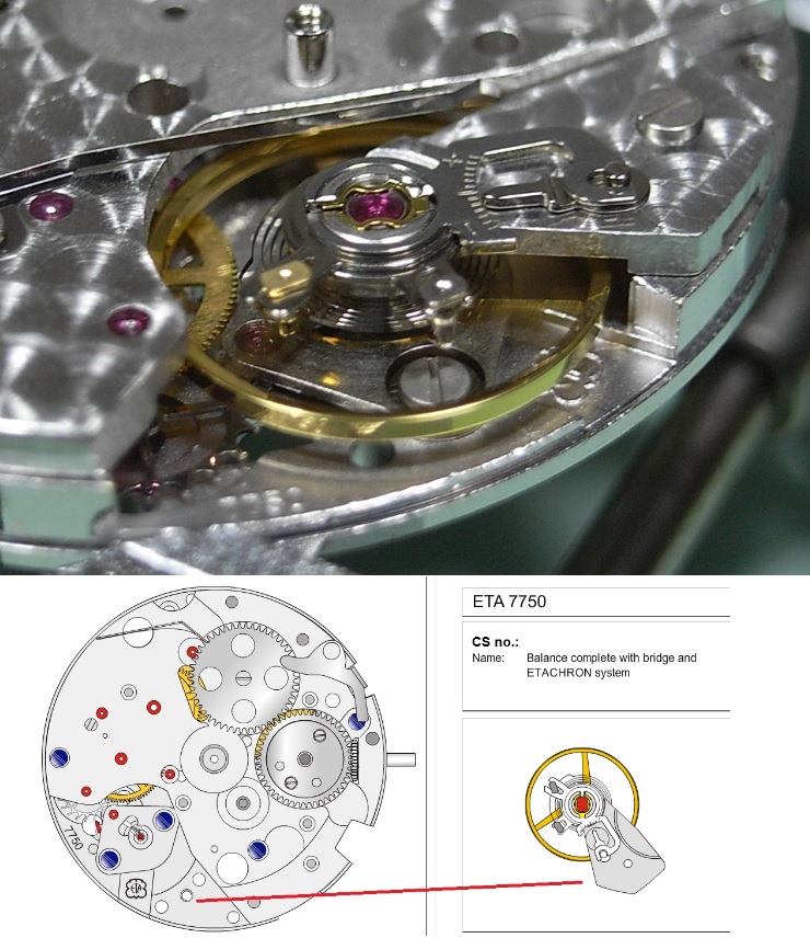
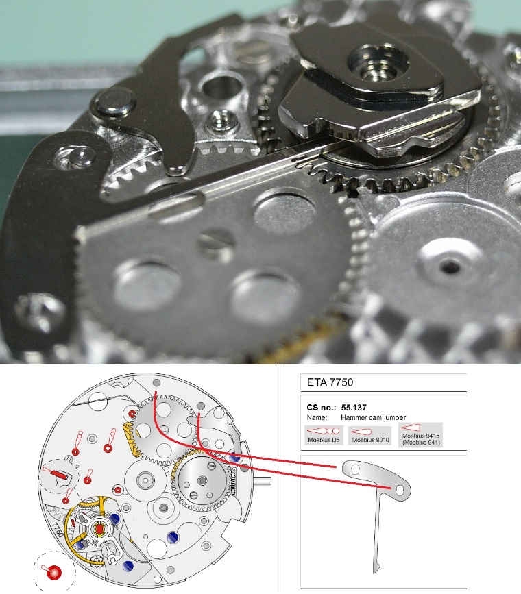
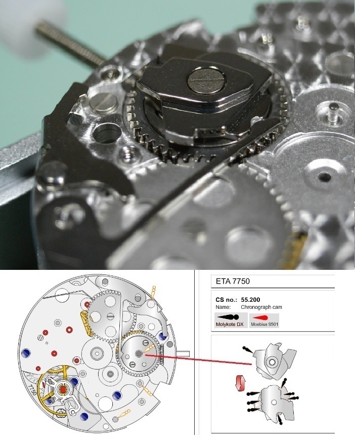
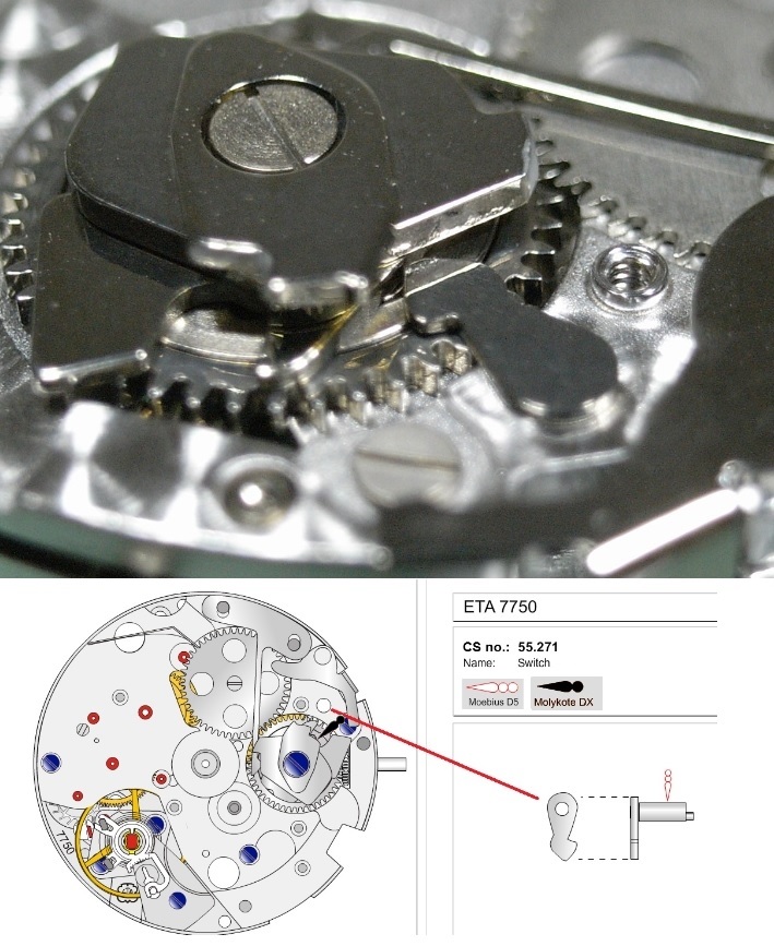
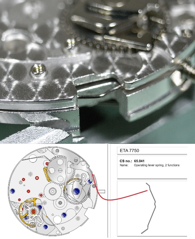
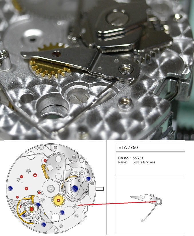
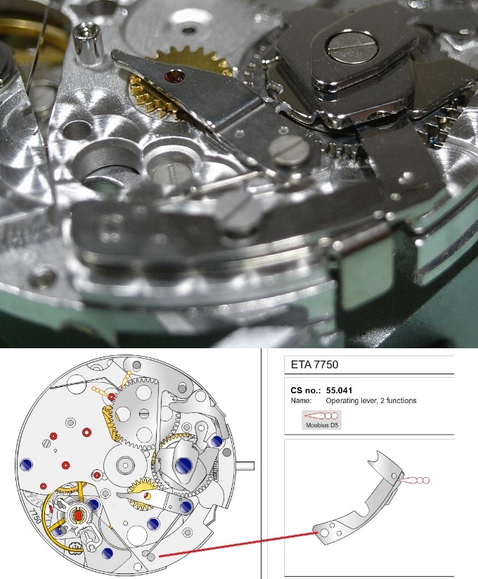
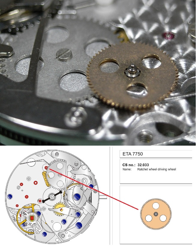
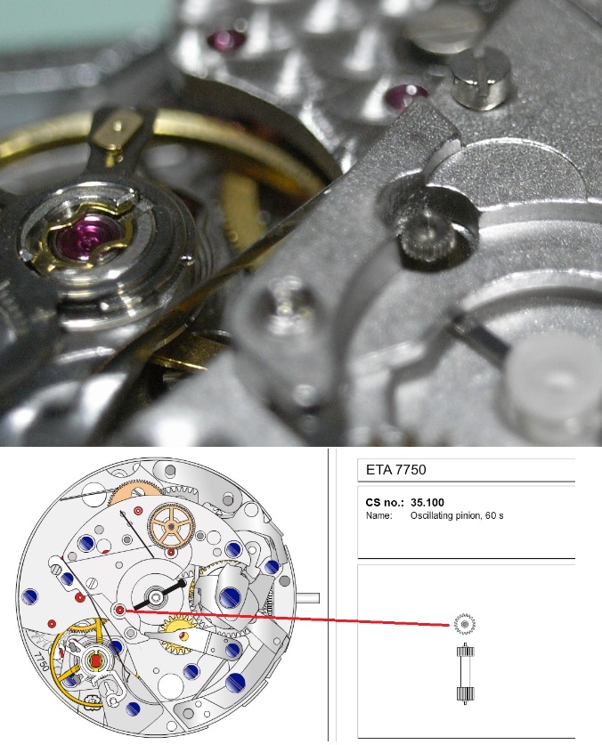
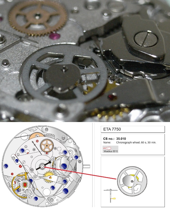
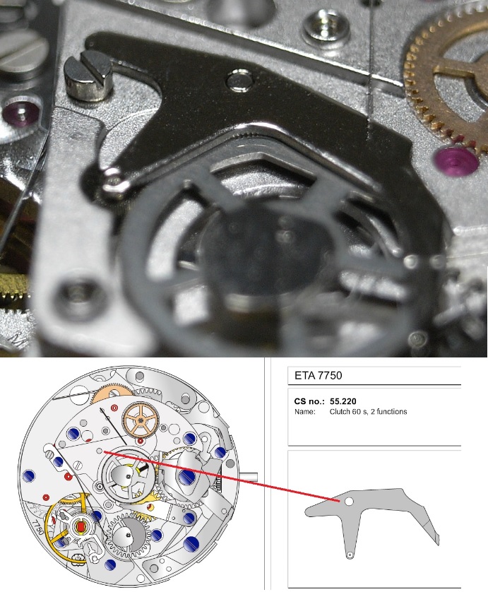
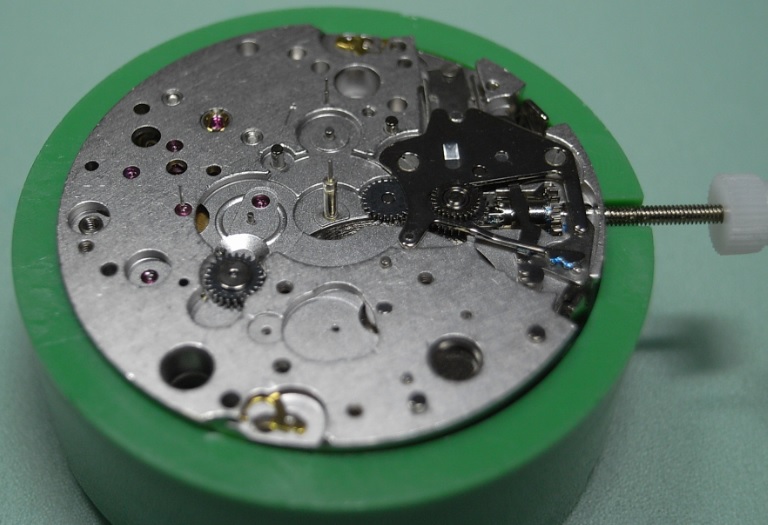
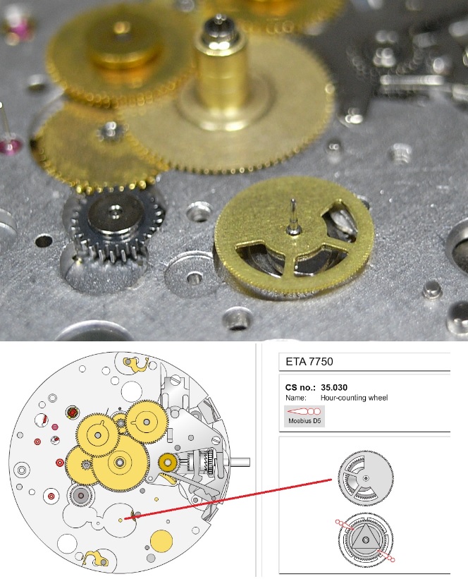
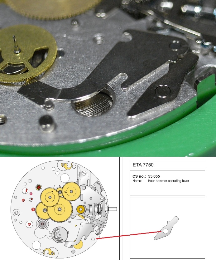
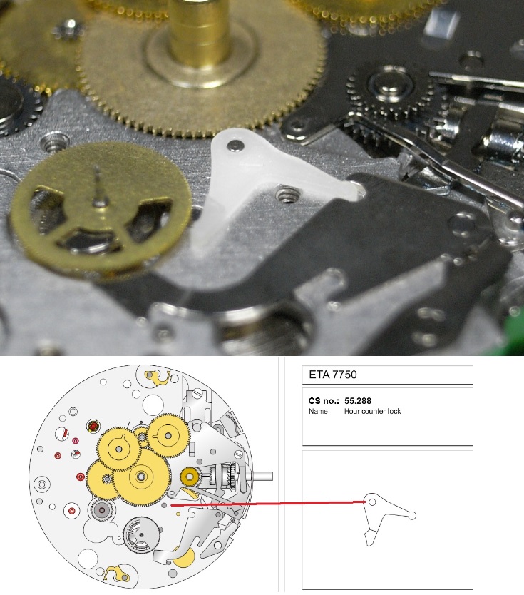
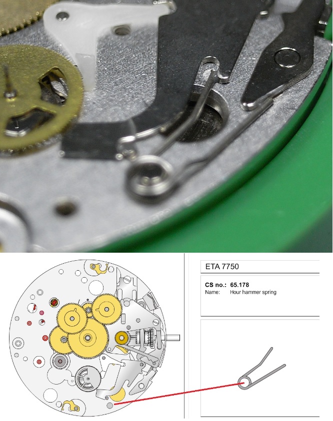
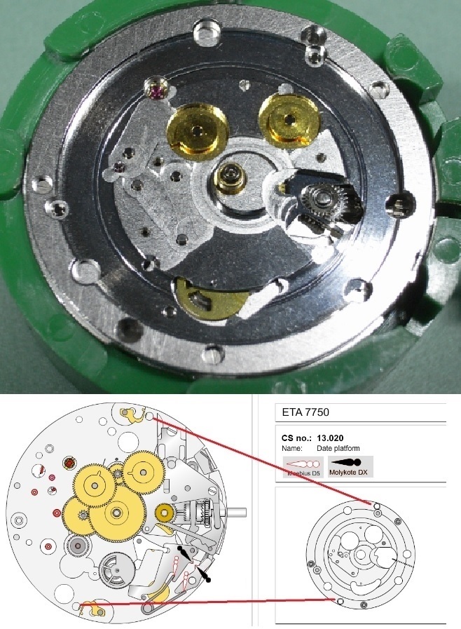
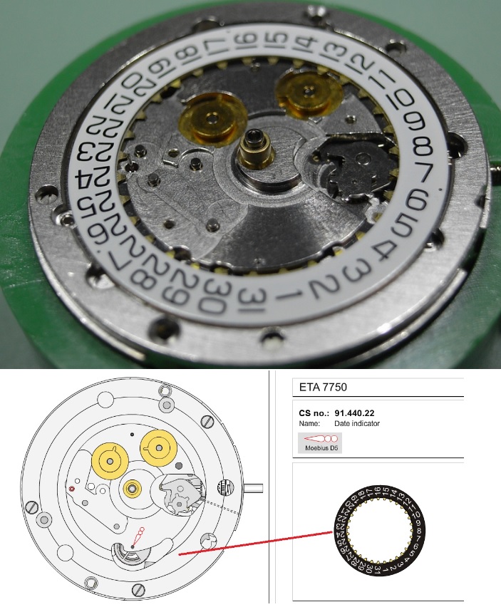
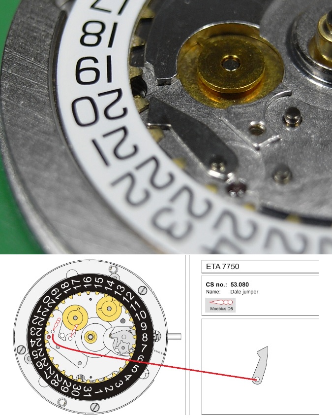
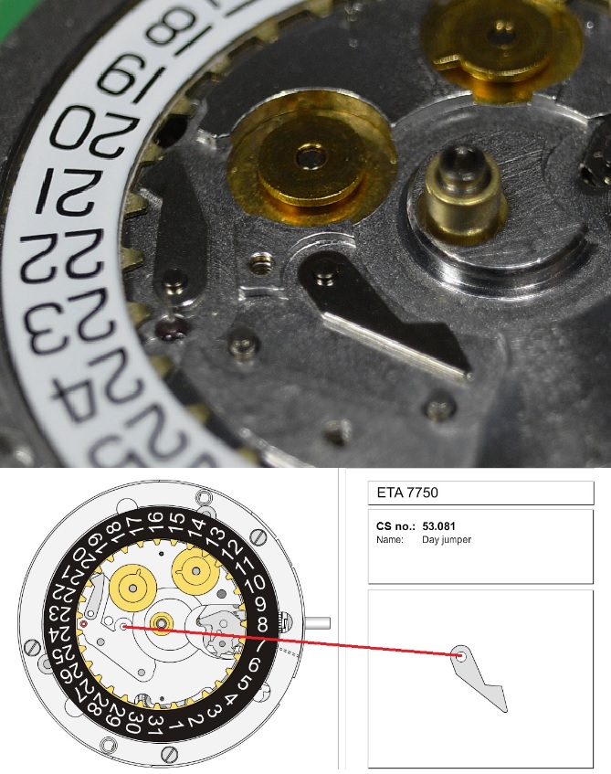
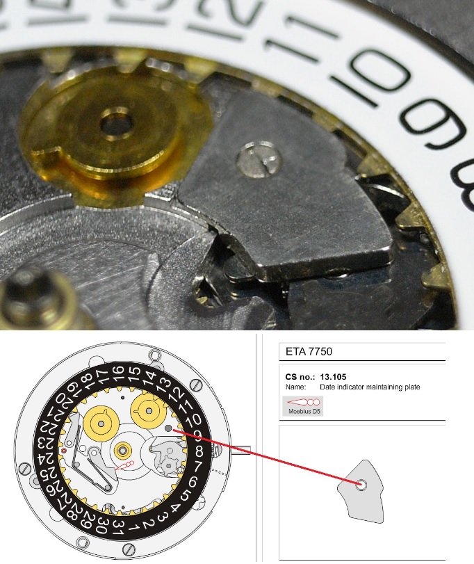
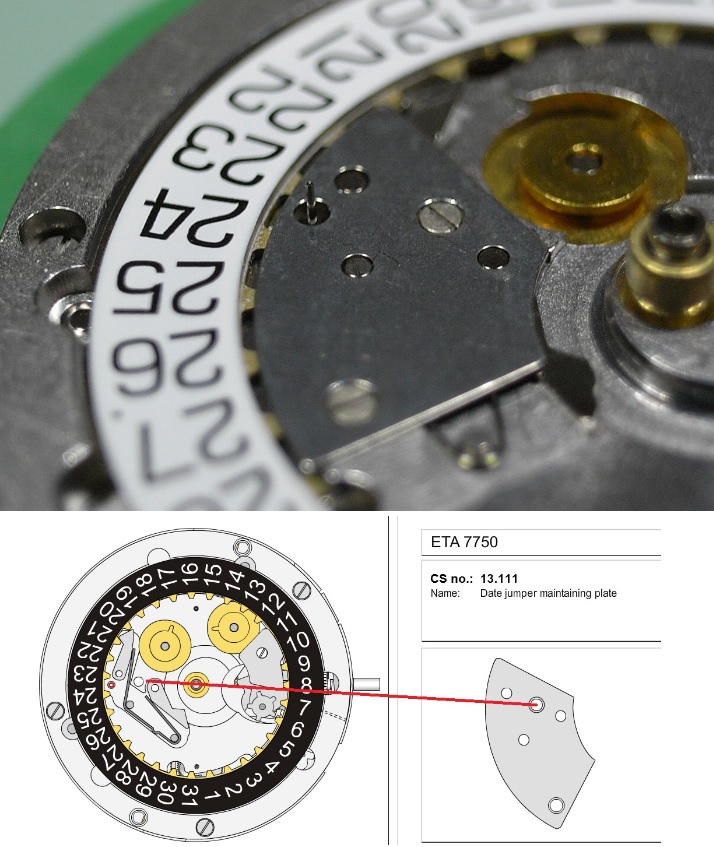
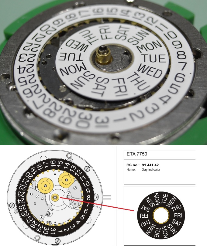
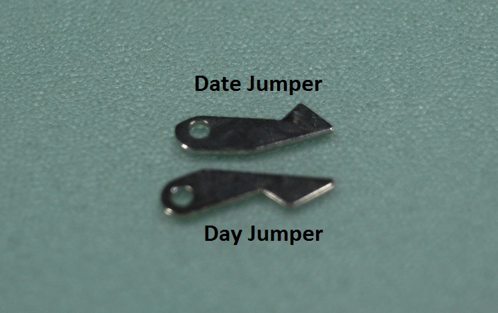
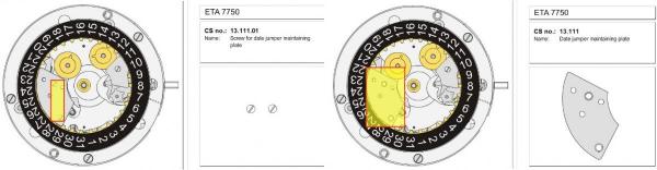
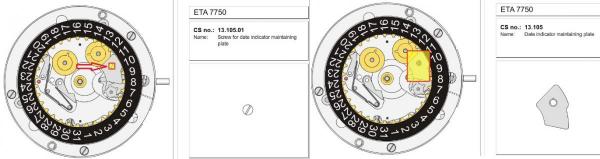
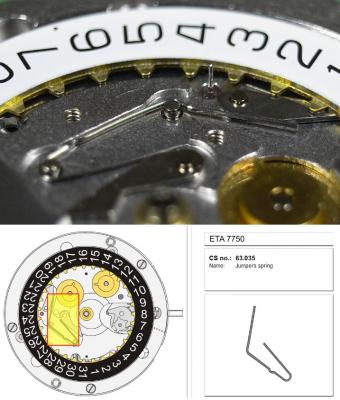
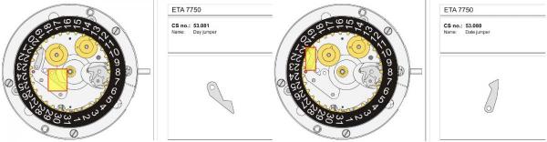
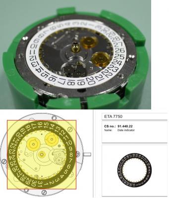
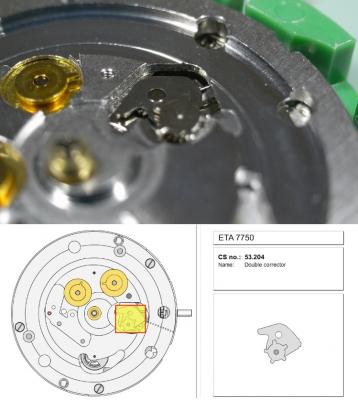
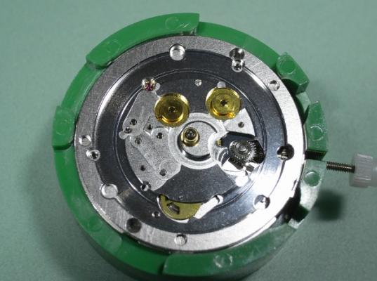
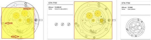
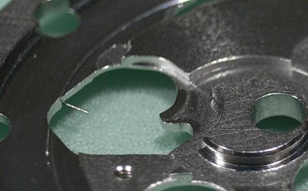
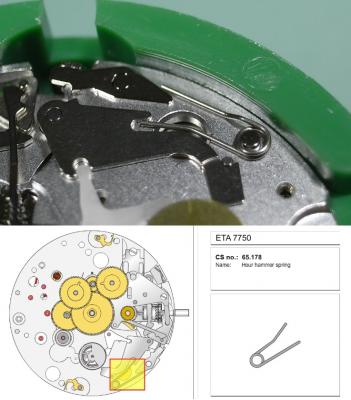
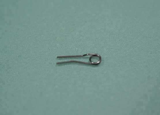
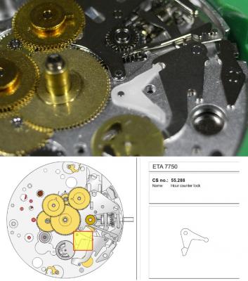
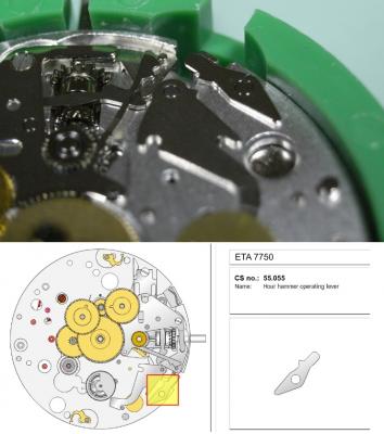
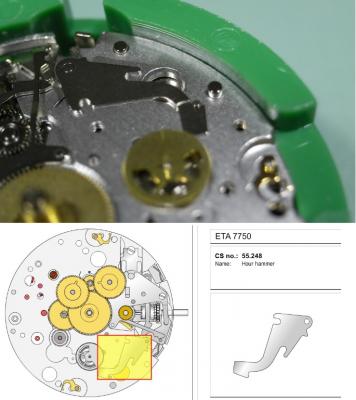
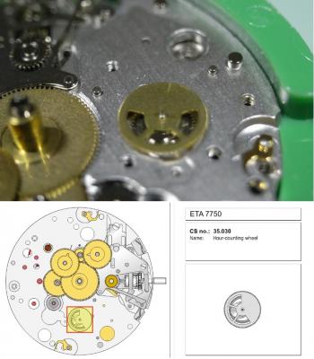
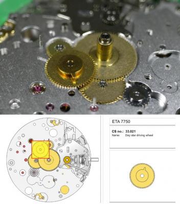
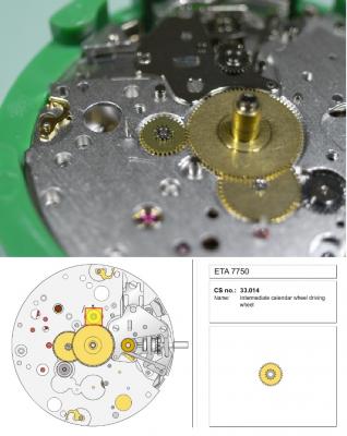
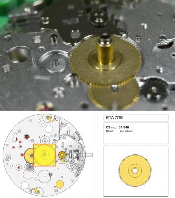
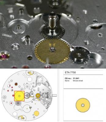
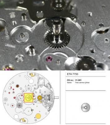
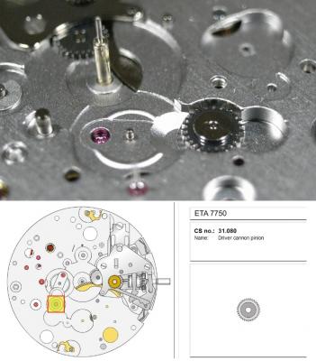
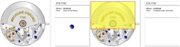
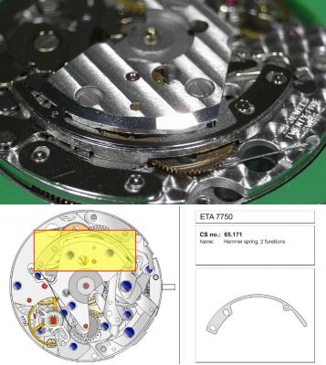
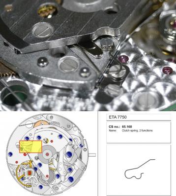
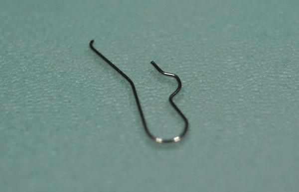
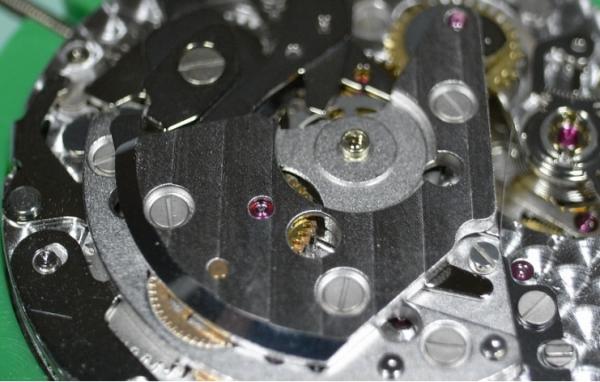
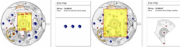
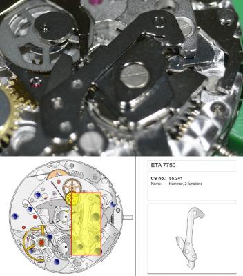
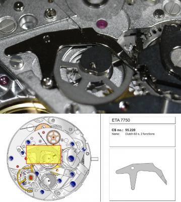
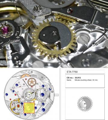
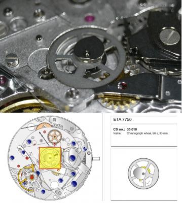
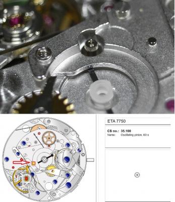
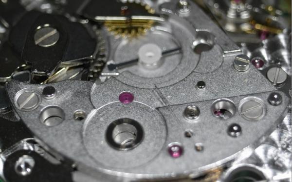
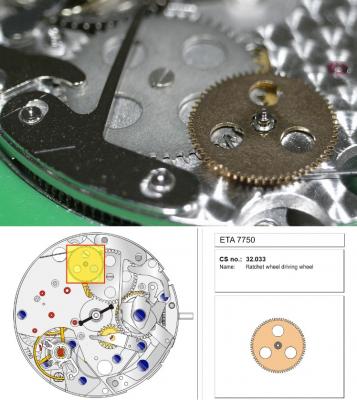
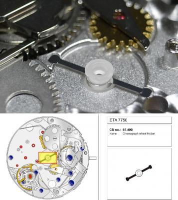
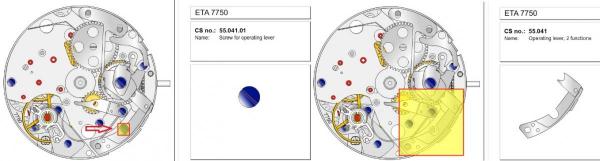
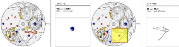
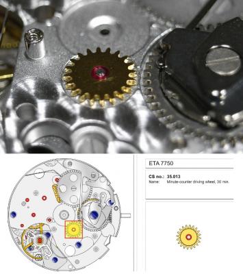
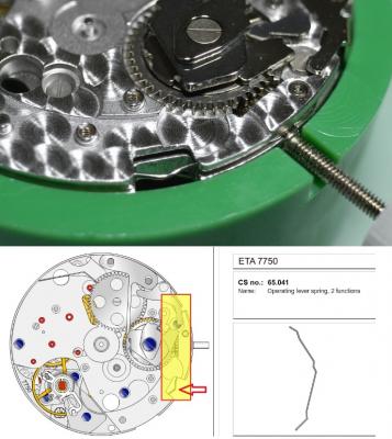
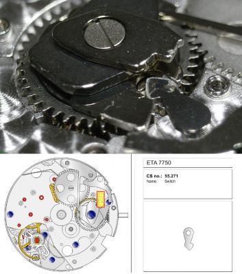
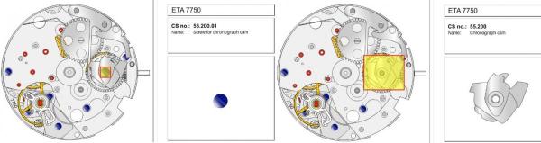
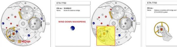
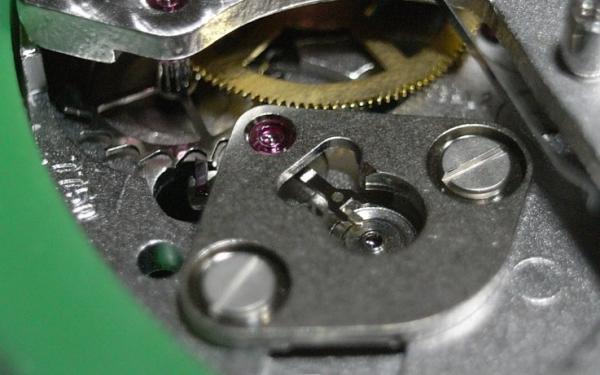
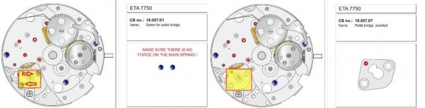
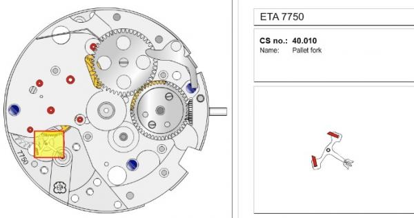
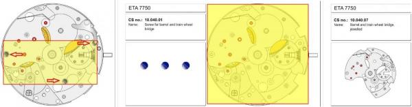
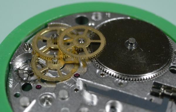
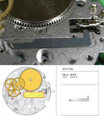
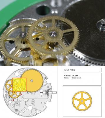
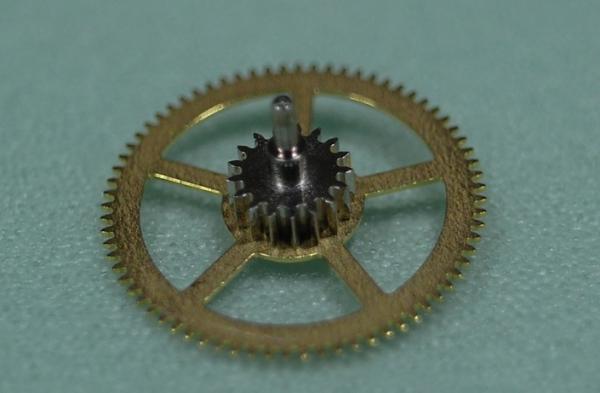
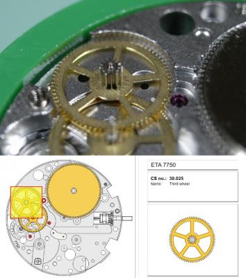
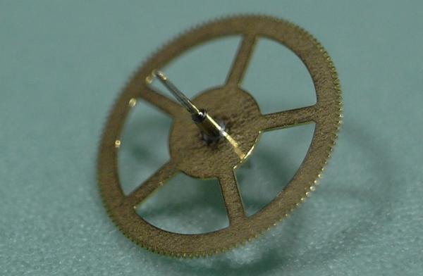
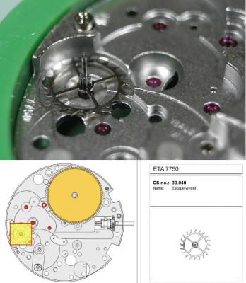
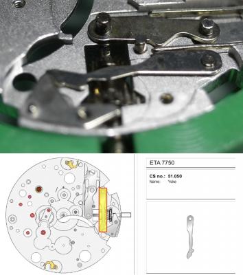
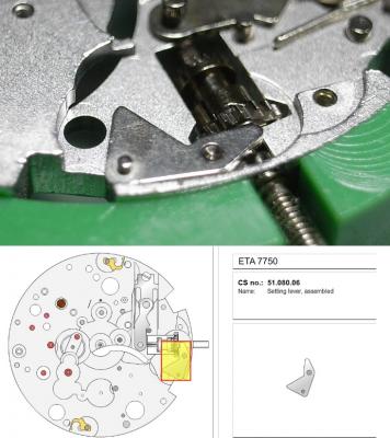
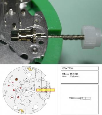
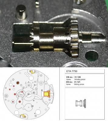
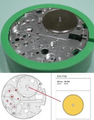
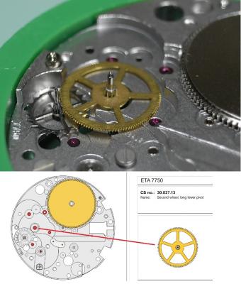
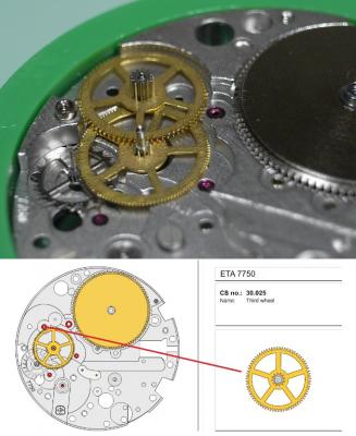
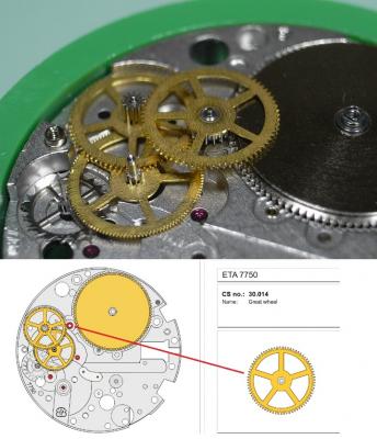
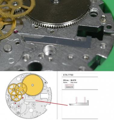
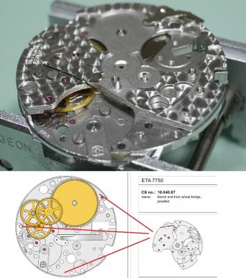
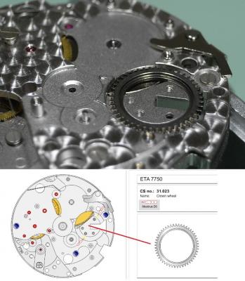
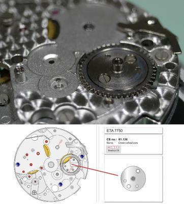
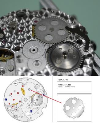
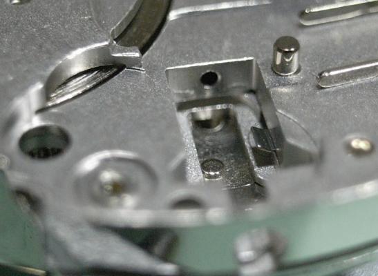
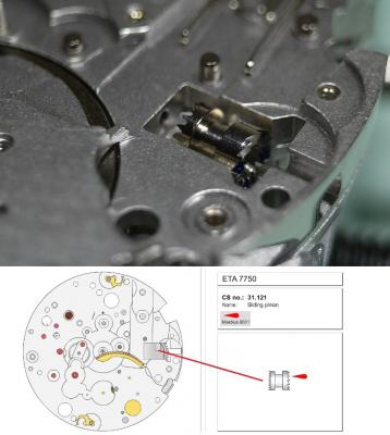
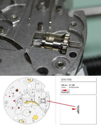
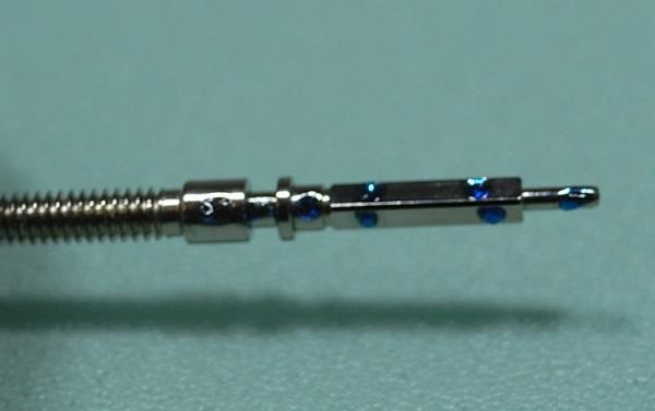
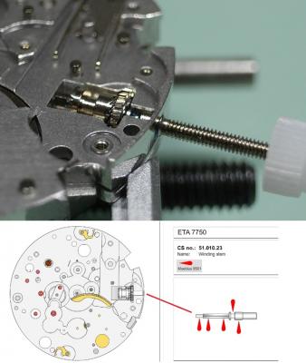
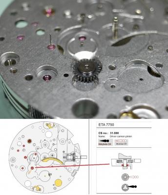
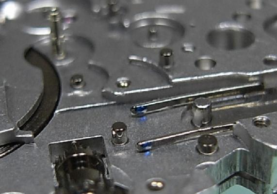
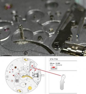
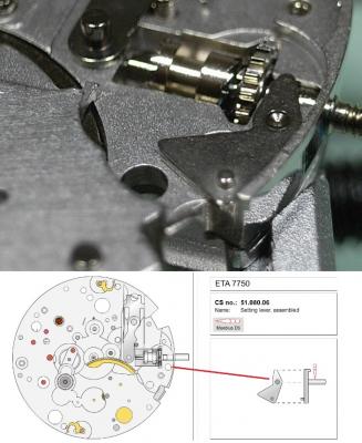
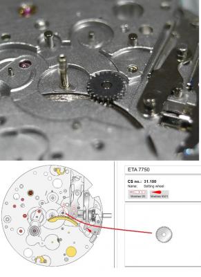
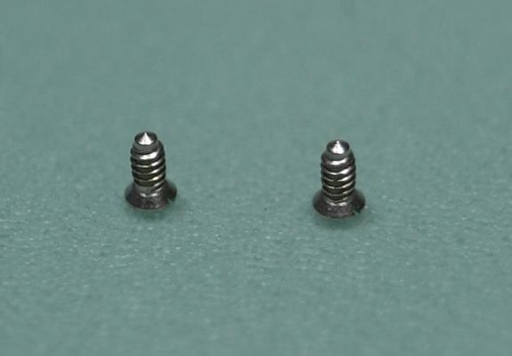
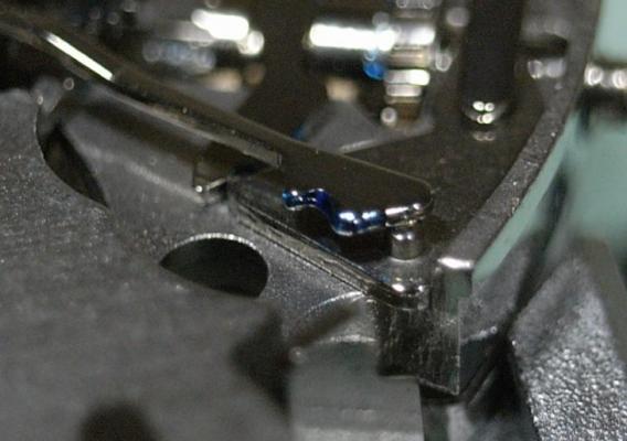
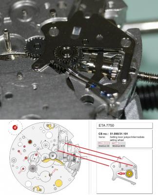
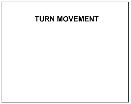
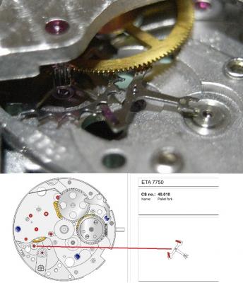
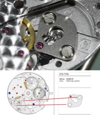
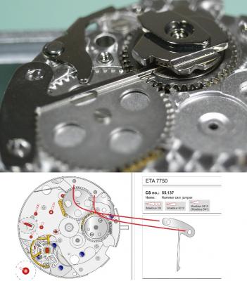
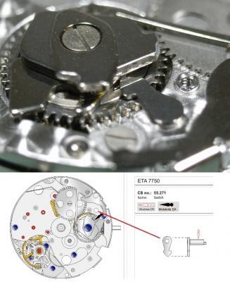
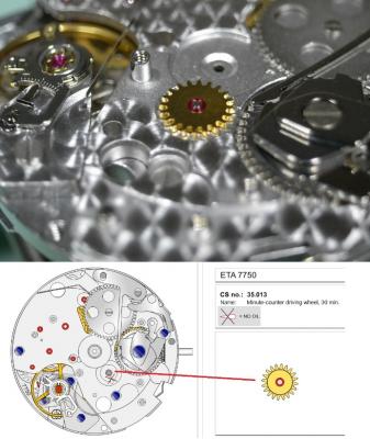
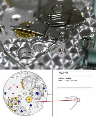
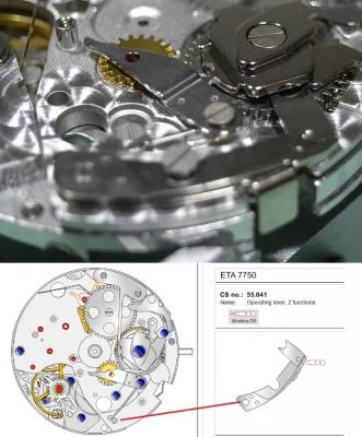
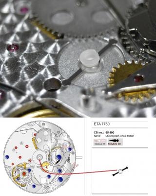
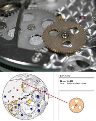
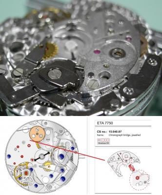
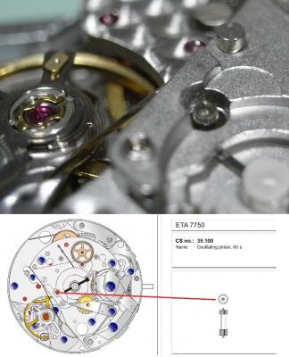
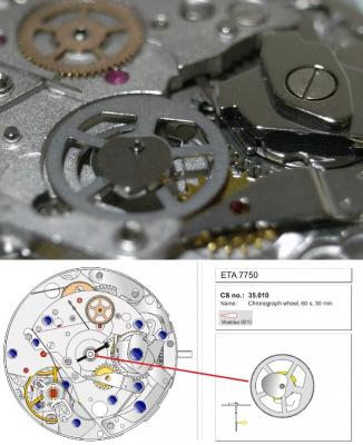
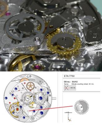
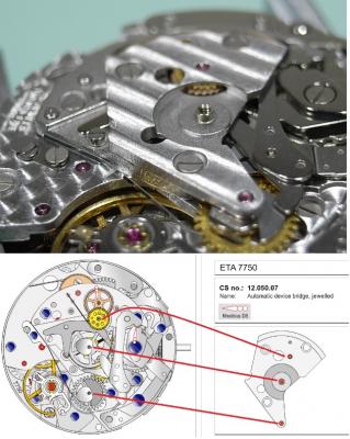
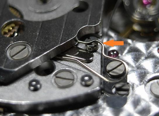
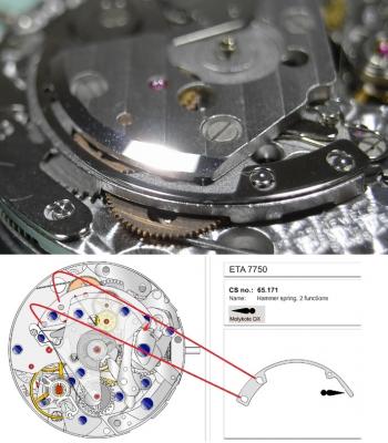
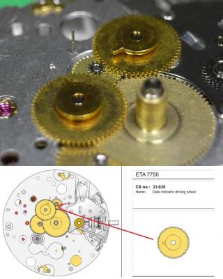
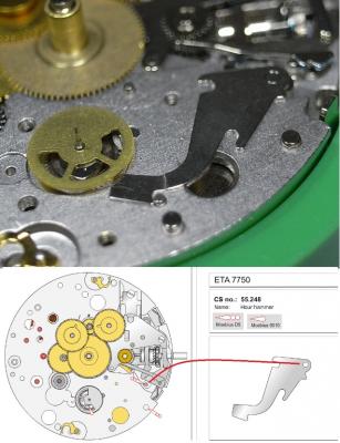
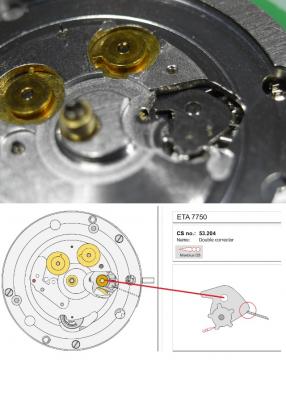
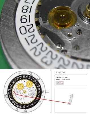
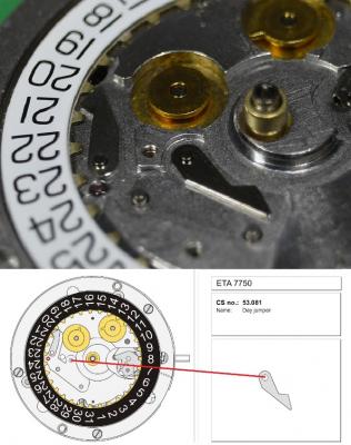
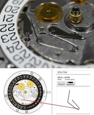
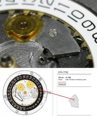
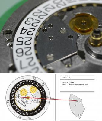
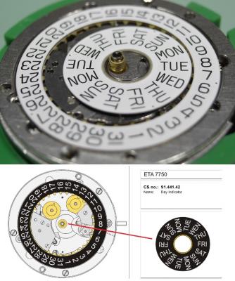
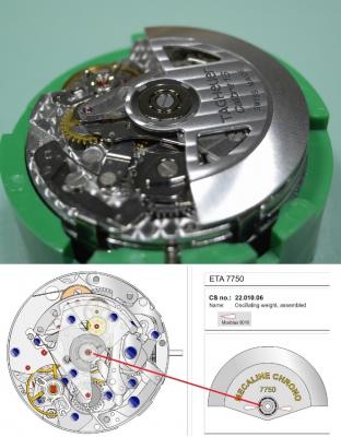
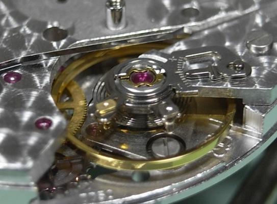
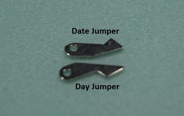
ETA 7750 Service Walkthrough The 7750 was first available in 1974, having been one of the first movements to be designed with the aid of a computer. It's hard to believe that the 7750 is still the industry standard movement for chronographs considering it's history. It was developed over 40 years ago by Valjoux, who was then a legendary movement maker that was part of the giant ASUAG conglomerate. But by the end of 1975 production was stopped due to the onslaught of the Quartz Era, and the 7750, along with many other mechanical calibers, was abandoned. Industry demand for this movement was so low that the stock produced in that 1 year manufacturing lasted until 1982! Such was the devastation of cheap Japanese produced quartz watches to Swiss manufactures. History may have forgotten the 7750 except for the local management at Zenith who ignored the orders by Valjoux to destroy the dies and equipment used to manufacture the 7750, instead hiding the equipment away from corporate eyes. You can find many more fascinating facts about this caliber online, and it's well worth the read. ................................................... This walkthrough will be very detailed, and I hope this will give people the courage to tackle this movement. I've serviced quite a few calibers, and this is one of the most beautiful, with a very logical layout. ETA7750 Tech.PDF If you have built your skills with basic movements, and become proficient in servicing them, I would highly recommend this movement to be your first chronograph to tackle. Lets begin. DEMAGNETIZE THE MOVEMENT BEFORE DISASSEMBLY. Remove the Day Indicator and store it in a safe place where it won't be damaged. Unscrew (0.8 Driver) the Jumper Maintaining Plate and remove it. Do the same for the Date Indicator Maintaining Plate Carefully remove the Jumpers Spring, holding it with a piece of pegwood so it doesn't ping away. Next remove the jumpers for the day and date. The jumpers differ from one another, so here is a reference photo so you can see the difference. Remove the Date Indicator and place it in a safe place where it won't be damaged. The last piece to remove on the Date Platform is the Double Corrector Now unscrew (1.4 Driver) the Date Platform and gentle pry it from the movement. Be careful when removing this plate, as there is a fine spring pressed into the plate that can be easily damaged. Here is a reference photo of the screws that hold the Date Platform. Remove the Hour Hammer Spring, once again using the pegwood to hold the spring while removing the tension. Here is a reference photo of the correct orientation of the spring. Remove the Hour Counter Lock. Remove the Hour Hammer Operating Lever. Next is the Hour Hammer, be careful when removing this item so as not to damage the Hour-Counting Wheel. Now remove the Hour-Counting Wheel. Remove the Date Indicator Driving Wheel Remove the Day Star Driving Wheel Then remove the Intermediate Calendar Driving Wheel Remove the Hour Wheel Then the Minute Wheel Remove the Cannon Pinion, which does not require a puller. The last component to be removed on this side of the Main Plate is the Driver Cannon Pinion. To lift the Driver Cannon Pinion I used what Mark used, a set of hand lifter from Horotec (MSA05.007); but you can also use a Presto Tool (30636-1) which will also work well. The dial side of the movement is now complete disassembled. Flip the movement over and unscrew (1.5 Driver) the Oscillating Weight. To remove the Hammer Spring lift it up gently over the automatic work and move it inwards. This will move the tail of the spring in a clockwise motion to the opening in the slots, which will free the spring. Slide out the Clutch Spring. Here is a reference photo of this spring, and it's orientation. Remove the screws (1.4 Driver) for the Automatic Device Bridge, and gently pry it loose. Here is a reference photo of these screws for the bridge. Once the Automatic Bridge has been removed, the two wheels for the automatic work are able to be removed. Below is a reference photo of how the sit inside the bridge. We now begin to disassemble the chronograph section of this movement. Begin with removing the Hammer, 2 Functions. Next remove the Clutch 60s, 2 Functions. Then remove the Minute-counting Wheel, 30min. Remove the Chronograph Wheel 60s, 30min. Gently lift out the Oscillating Pinion, 60s. Here is a reference photo of the orientation of this pinion. Unscrew (1.4 Driver) the Chronograph Bridge and gently pry it off the Train Wheel Bridge. Remove the Ratchet Driving Wheel. Remove the Chronograph Wheel Fiction. Unscrew (1.4 Driver) the Operating Lever, 2 Functions. Unscrew (1.4 Driver) the Lock, 2 Functions. Next remove the Minute-counter Driving Wheel, 30min. Slide out the Operating Lever Spring, 2 Functions. This spring can be fitting in both directions; but only 1 way is correct. Here is a reference photo of it's correct orientation. Remove the Switch. Here I digress from the order the SwissLab document illustrates the order of removal. They show to remove the Chronograph Cam before removing the Hammer Cam Jumper. This in my opinion is not the best way, as all the force from the jumper is pressing on the cam whilst your trying to remove it, and could lead to damage. Instead I move the Chronograph Cam until it reaches the notch as shown in the photo below. Then lift the Hammer Cam Jumper up to the top of the Chronograph Cam, which will release it's tension. Then, just as you removed the previous hammer, rotate the jumper to the opening in the slots, which will free the spring. Now you can unscrew (1.4 Driver) and remove the Chronograph Cam safely without tension on it. RELEASE THE MAINSPRING TENSION Once the tension has been released, unscrew (1.4 Driver) and remove the Balance Cock. Then unscrew (1.4 Driver) the Pallet Bridge and remove the bridge and Pallets. Unscrew (1.2 Driver) and remove the Ratchet Wheel. Then remove the Crown Wheel. Unscrew (1.4 Driver) the Train Wheel Bridge and gently pry it off the Main Plate. Note that one of the screws is under the Operating Lever. This needs to be moved out of the way to access this screw. The last level of this movement contains the train. Here is a reference photo of the wheel locations. Remove the Stop Lever. Remove the Great Wheel. Here is a reference photo of the underneath of this wheel. Remove the Third Wheel. Here is a reference photo of the underneath of this wheel. Remove the Second Wheel. Here is a reference photo of the underneath of this wheel. Note this has the long lower pivot. Remove the Escape Wheel. Here is a reference photo of the underneath of this wheel. Then remove the Barrel. This completes the removal of the train. Flip the movement over so we can complete the disassembly by removing the keyless work. Firstly, release the tension from the Setting Lever Jumper. Then unscrew (1.2 Driver) and remove the Setting Lever Jumper. These are unique screws with pointed ends, and below is a reference photo of them. This will also remove the Intermediate Setting Wheel. Next remove the Setting Wheel Then remove the Yoke. Remove the Setting Lever. Remove the Rocking Bar. Now pull out the Stem. Once the Stem is removed the Winding and Sliding Pinion should fall out of the movement onto your work mat. Disassembly of the 7750 is now complete If you've come this far, congratulation on completing the disassembly. Make sure you pegwood all the jewels and reinstall the Balance back onto the movement for cleaning. Assembly of the movement will be posted as soon as I complete the write-up.


 1 point
 -
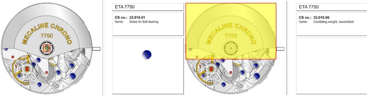
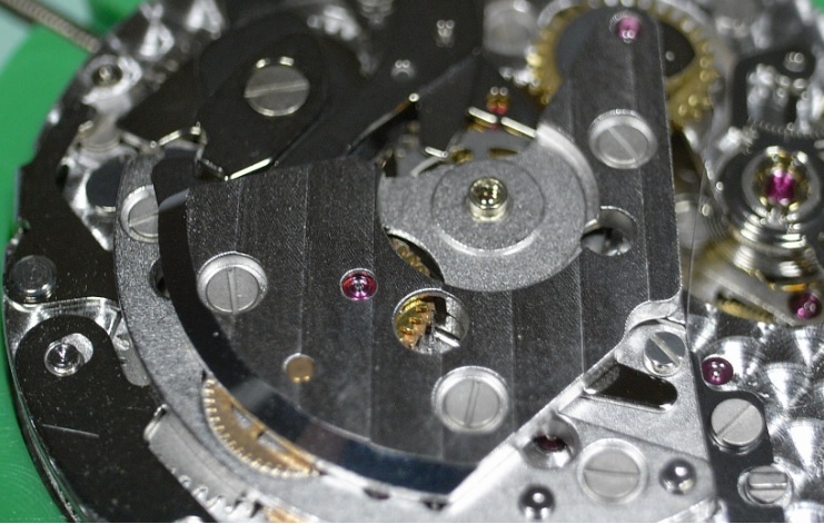
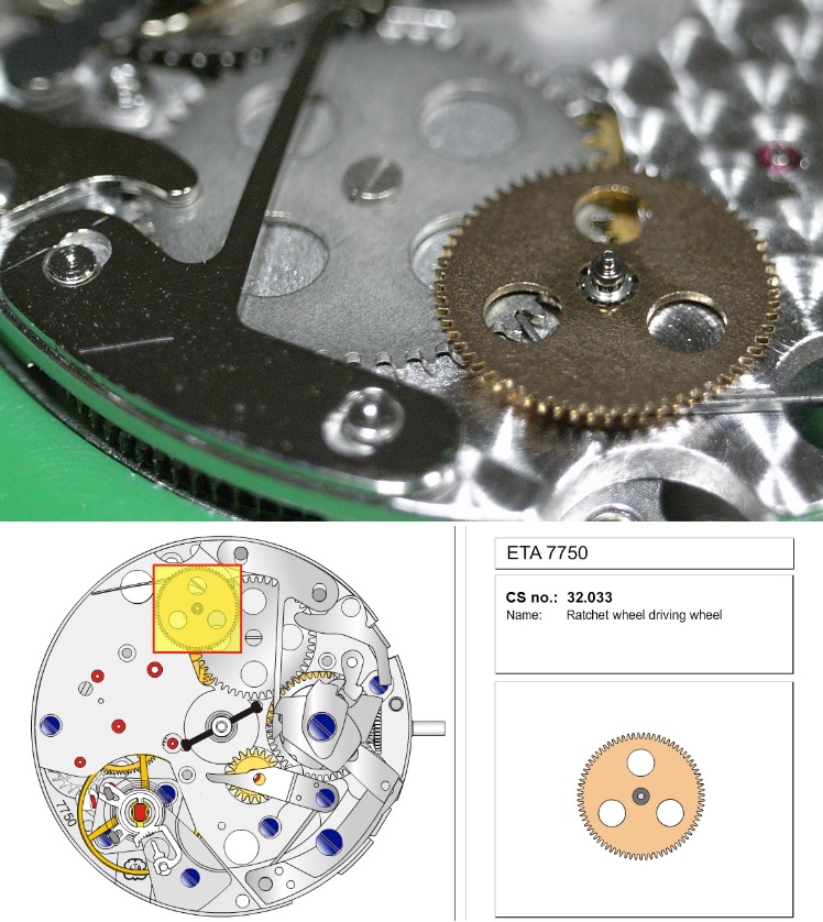
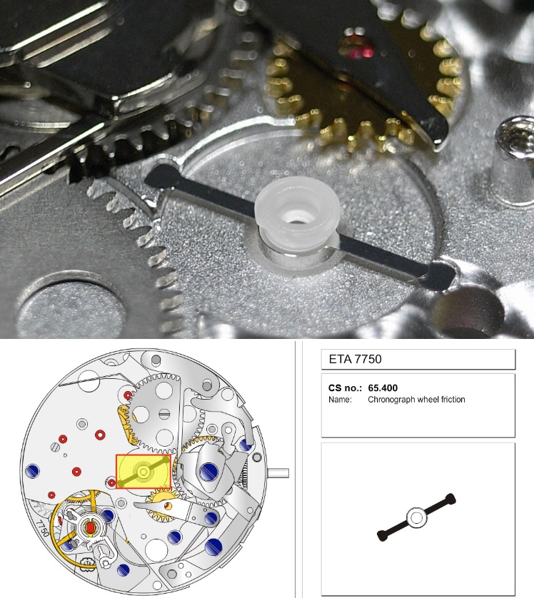
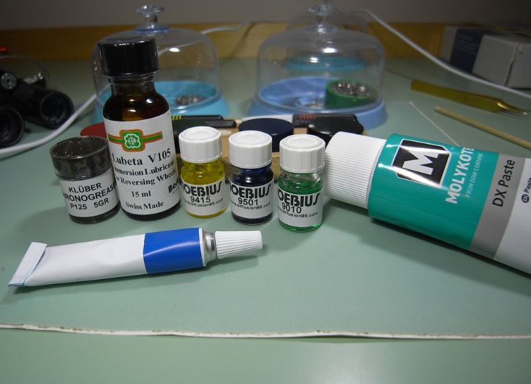
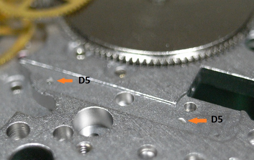
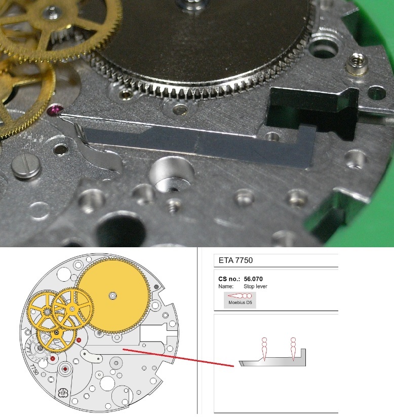
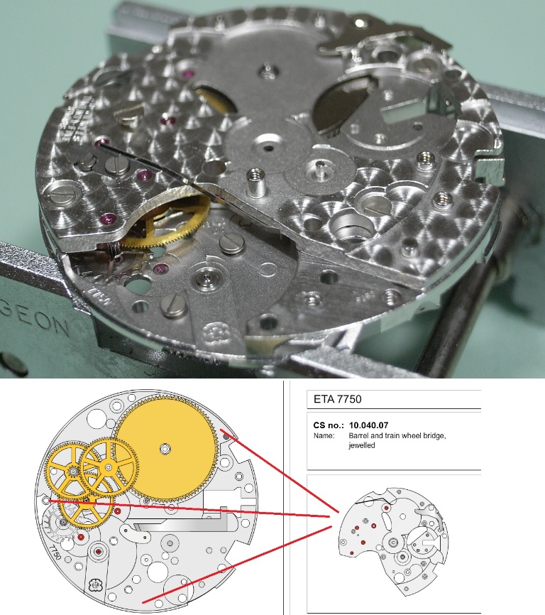
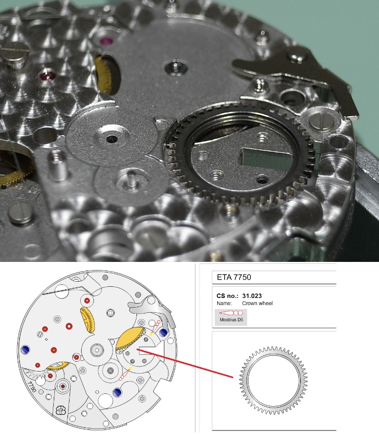
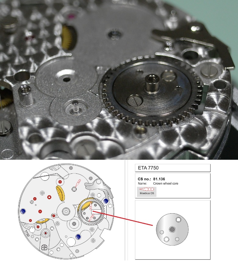
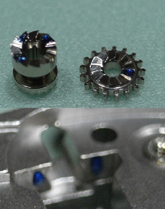
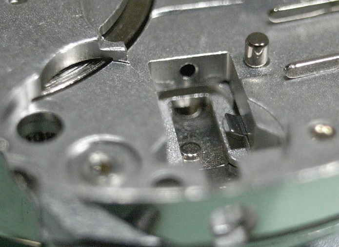
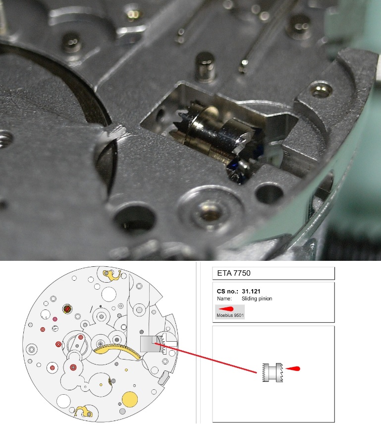
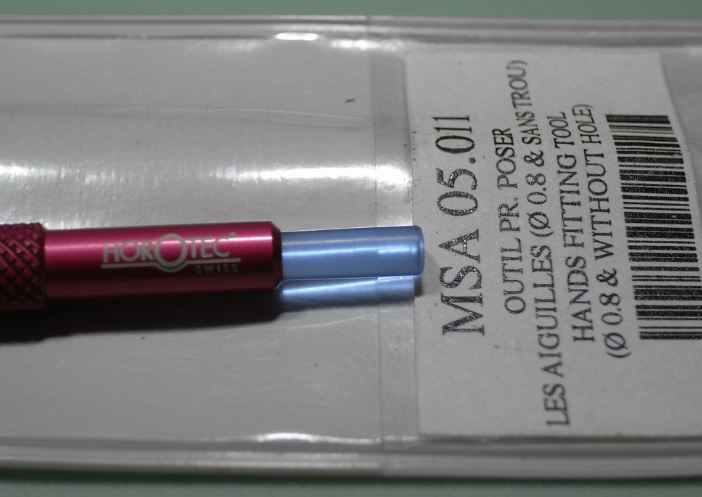
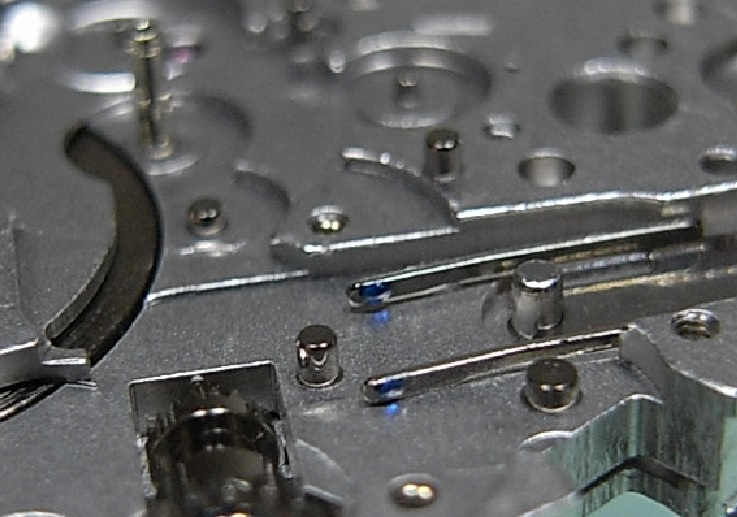
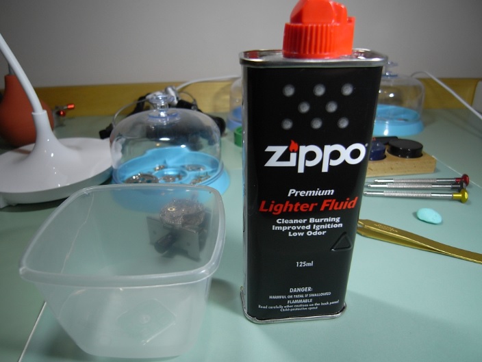
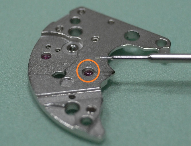
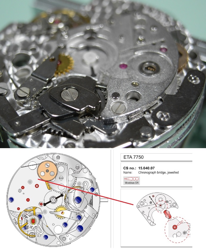
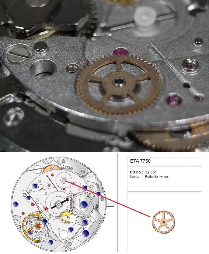
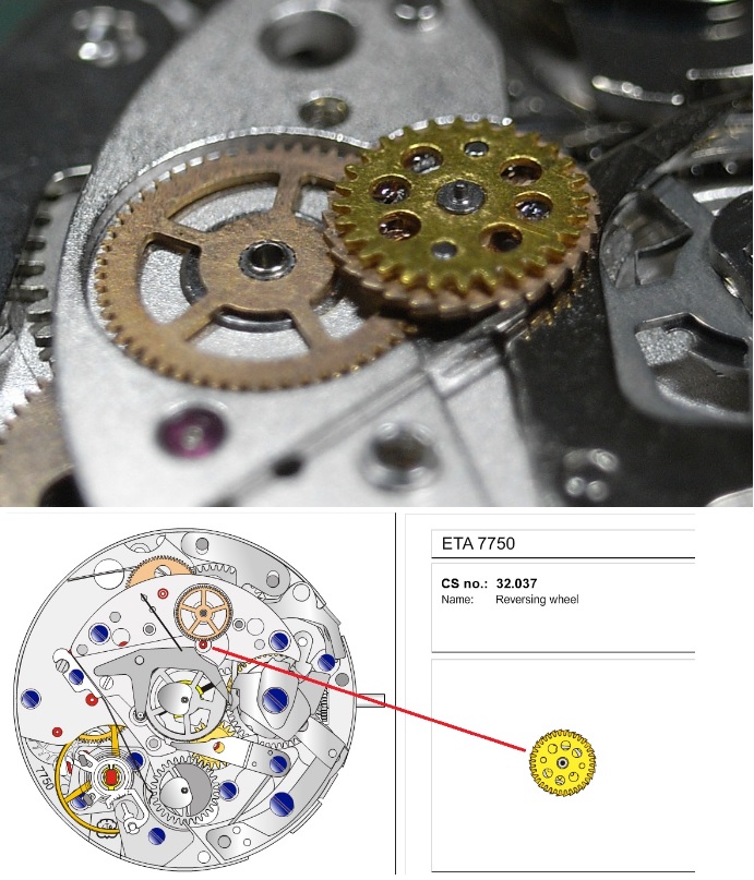
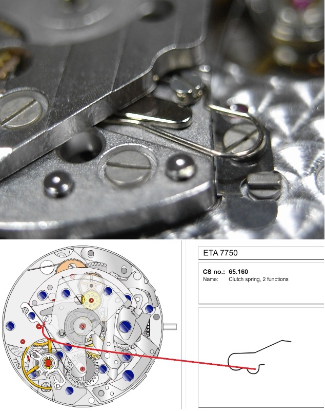
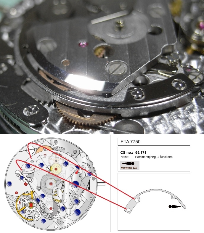
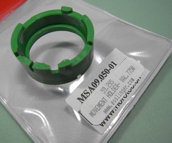
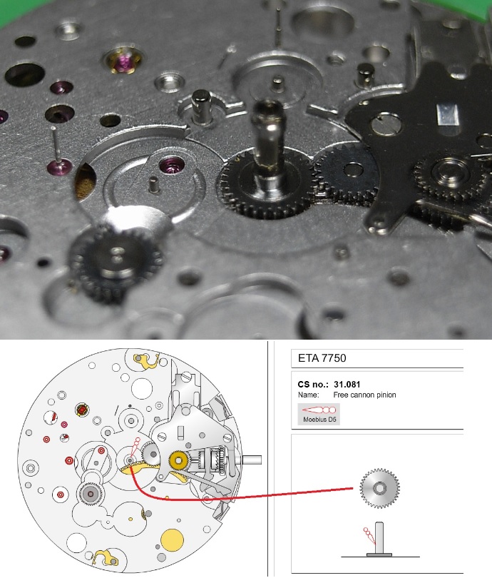
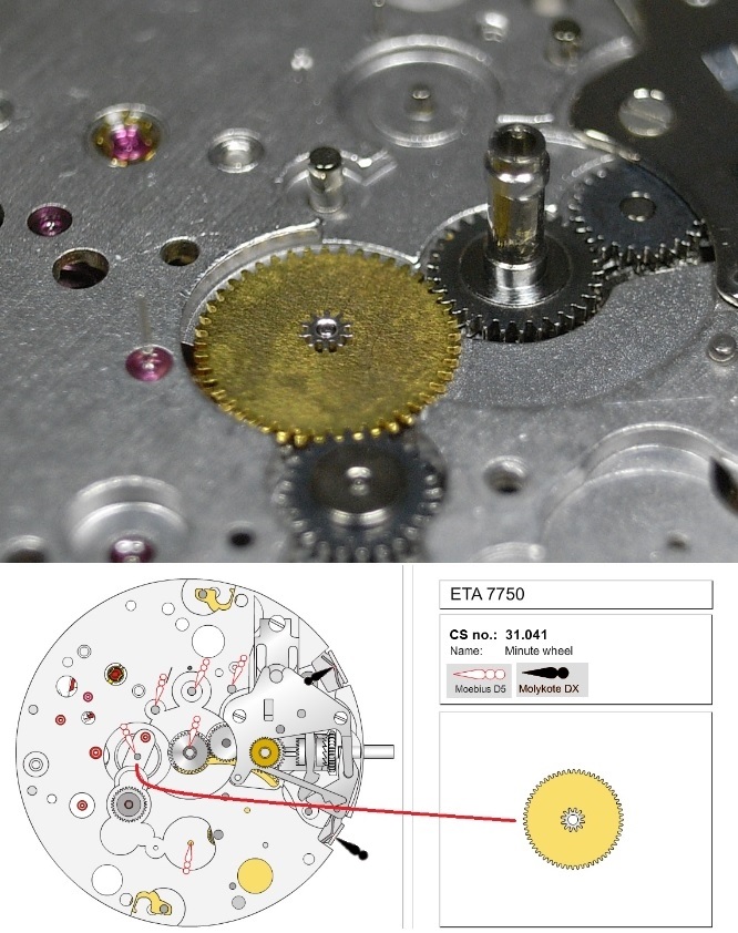
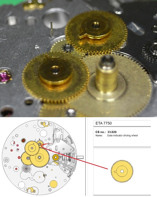
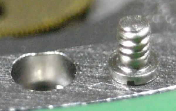
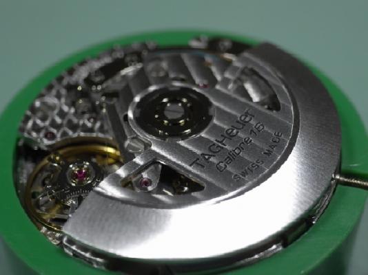
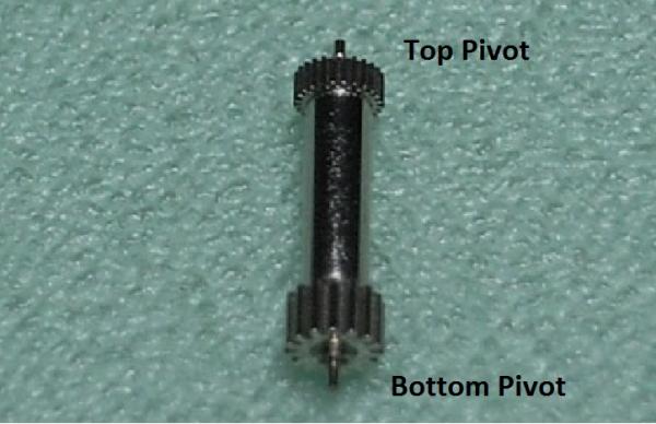
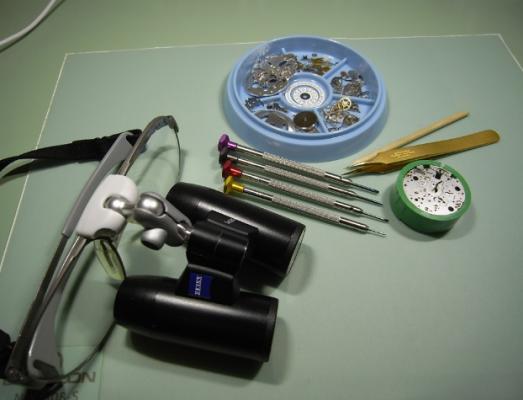
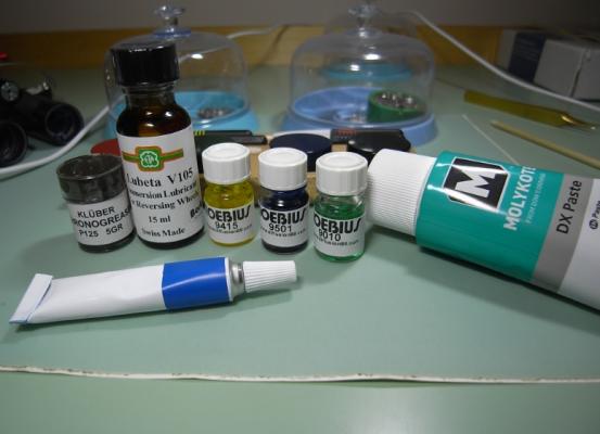
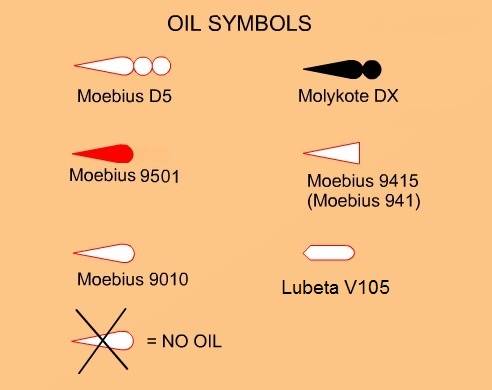
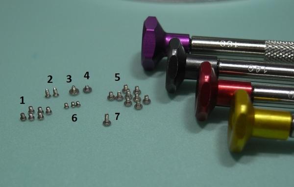
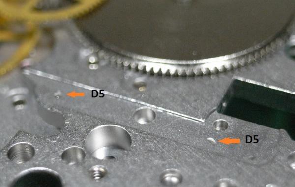
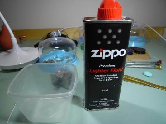
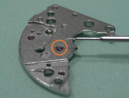
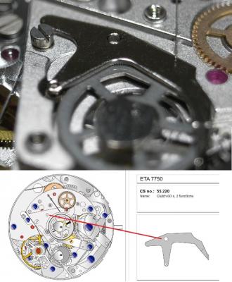
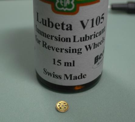
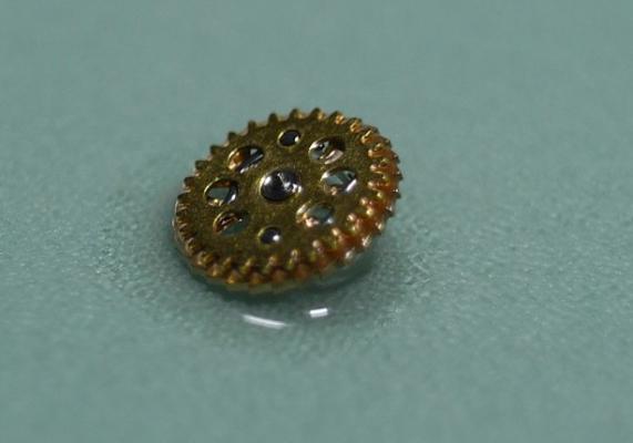
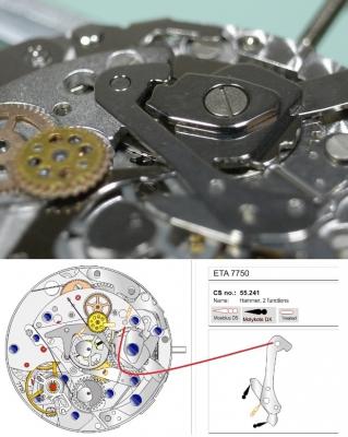
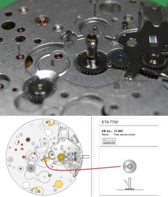
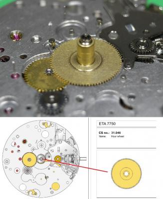
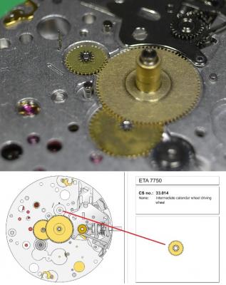
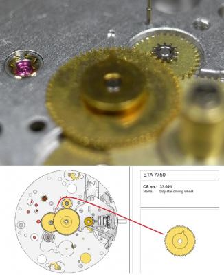
ETA 7750 Walkthrough Part 2 Assembly Now we come to assemble the movement. Here are the lubricants that will be used. Now nothing creates more discussion and controversy than which lubricants should be used on movements in various applications. This is how I approach it ... your choices may vary. The 7750 I am servicing here is a "Top Grade" ETA movement made for TAG, which would normally be cased with a display back. Because of this I will be using Molykote DX instead of Jismaa 125 or 9501 grease for areas that will be seen. As their lubricating qualities are very close, my choice of using Molykote DX is purely for ascetic reasons, as its less visible to the eye, then the bright colours of the 9501 and Jismaa 125. You will notice that Molykote DX is recommended in the 7750 PDF; yet on the SwissLab documentation it states to use Jismaa 125, so all these lubricates are recommended and safe to use. If this was a "Standard" or "Elabore" Grade movement with a full metal caseback, then I'd just go with the SwissLab recommendations, or 9501 for ease of servicing. With all that being said, here is the Lubrication Index for this walkthrough. Housekeeping Make sure your work area has been wiped down to remove any dust, and clear away any unneeded items from around your workspace. Inspect your Screwdrivers and Tweezers, and dress them up if needed. There is nothing worse than marring a screwhead, or have components ping from your tweezers because they need to be re-dressed. Put on some finger cots, or latex gloves. Personally, I use only one latex glove on my left hand, as any manipulation with my right hand will be done with my old trusty customized Dumont Brass #4 tweezers. NEVER touch cleaned parts with bare hands, this will leave prints and tarnish the finish over time. We begin with the parts fresh from cleaning. Try and arrange them in a logical order to start with, this will save you time fishing for parts later on. The 7750 has 7 types of screws, and you'll need 4 sizes of screwdrivers - 0.8, 1.2, 1.4, 1.5mm 1) Date Platform, Crown and Ratchet Wheel Screws 2) Setting Lever Spring Screws (Note the pointed ends) 3) Hammer and Cam Screws 4) Oscillating Weight Screw (Single Screw with the short thread) 5) Pallet Fork, Main Plate, Chronograph Plate, Automatic Work Plate Screws 6) Screws for the Jumper Maintaining Plates 7) Single longer screw for the Balance Cock I like to arrange all the screws in groups like this, that way they are quick to find, and mismatching screws can't happen. One more thing to note on this assembly walkthrough, is that I started by using the 7750 plastic movement holder. I quickly however changed to a Bergeon 4040 movement holder, and found this much better when it came time to fit the plates and align pivots to their jewels. I'd suggest you use the Bergeon 4040 holder right from the get go. Lets begin! Place the Barrel on the Main Plate Next is the Escape Wheel Followed by the Second Wheel, which has the long pivot for the sub-dial hand. The Third Wheel is next to be installed With the last wheel in the train being the Great Wheel. Place 2 small spots of D5 as shown, so the Stop Lever will have a smooth action. Install the Stop Lever. Now install the Barrel/Train Bridge. (1.4 Driver) Make sure all pivots are located correctly and the train is free spinning BEFORE tightening down. Once tightened down check end shake. Install the Crown Wheel Then the Crown Wheel Core and screw down (1.2 Driver). Install the Ratchet Wheel and screw down (1.2 Driver). Once this is done, using a 1.2 Driver, turn the screw on the Ratchet Wheel a 1/4 of a turn to add energy to the Mainspring, and check the free running of the train. Next is the keyless work. Lubricate the Winding and Sliding Pinion as shown below. Also add a spot of 9501 to the Main Plate where the Winding Pinion will come in contact. Be sure when installing he Sliding Pinion that it's seated properly on the Stop Lever Install the Sliding Pinion Install the Winding Pinion Lubricate and install the Stem. Next is the Driver Cannon Pinion. This is one area that needs a lot of lubrication, as it will bind and damage the movement if it becomes dry. To install the Driver Cannon Pinion I use a Horotec Hand Fitting Tool MSA 05.011 Once properly lubricated, install the Driver Cannon Pinion Before installing the Rocking Bar, lubricate the points on the spring. Install the Rocking Bar. Install the Setting Lever Install the Yoke. Place the Setting Wheel on it's post. Construct the Setting Lever Jumper with the Intermediate Wheel As noted above, the screws for the Setting Lever Jumper are the ones with the pointy threaded ends. Be sure to lubricate position points on the setting bar before you lever it into place. Install the Setting Lever Jumper / Intermediate Setting Wheel. The keyless work is now complete, check it is functioning correctly, then turn the movement over. Once the movement is turned over install the Pallet Fork. Then install the Pallet Bridge. Once the bridge is in place, give the mainspring a few winds and check the free movement of the Pallet BEFORE screwing it down (1.4 Driver) After tightening down check the end shake. Use 9415 on the Exit Pallet Stone to lubricate the escapement. Replacing the Balance and oiling the Incabloc Jewels is next. Place the Balance back onto the movement, checking that it's free running before tightening the screw (1.4 Driver). Once tightened check side shake and end shake is correct. Remove the Incabloc Jewel, and then remove the Balance. Note the longer screw that is used to secure the Balance Cock. Cleaning them carefully by soaking in a container with Lighter Fluid ... I use Zippo Fluid. Once clean, dry the Balance and Incabloc Jewel and place a drop of 9010 on the Jewel as shown below. Make sure it covers at least 1/3 to 1/2 of the jewel, without the oil touching the sides of the jewel. Give the movement several winds to add some power to the Mainspring. Replace the Balance back on the movement and refit the Incabloc Jewel. Check that the Balance is oscillating freely. Then repeat the process for the jewel only on the Main Plate. Next to be installed is the Hammer Cam Jumper. Here is my method for installation. Place the Hammer Cam Jumper into position, turning it clockwise to lock it into the slots. Then place the Chronograph Cam on it's post, so that it rests on top of the cam jumper ... as shown below. Then while holding the arm of the cam jumper back, seat the Chronograph Cam into position and affix the screw (1.4 Driver) Install the Switch Insert the Operating Lever Spring, 2 Functions. Make special note of the orientation of this spring, as it will fit in both directions; but only one way is correct. Without lubricating, install the Minute-counter Driving Wheel, 30min. Install the Lock, 2 Functions, and screw down (1.4 Driver) Before installing the next item, which is the Operating Lever, 2 Functions, be sure to lubricate the hinging point from underneath with D5. Then install the Operating Lever, 2 Functions. Be sure that the spring arm of the Lock is out from under the Operating Lever and screw down (1.4 Driver). Place D5 into the little slot opening in the top of the hinge point. Install the Chronograph Wheel Friction. Install the Ratchet Wheel Driving Wheel Before placing the Chronograph Bridge onto the movement, you need to oil the jewel circled in the image below with D5 After oiling that jewel install the Chronograph Bridge. Next, place the Reduction Wheel into the hole in the Chronograph Bridge. Note that there is no post to locate this wheel, as it's on Automatic Device Bridge which will be installed later. The next item is the Oscillating Pinion which seems to cause people a lot of frustration. Here's my method to install it. Firstly, be sure of the correct orientation, as shown below. Pull the Crown out to the third position to engage the Stop Lever and hack the movement. Keep the movement in this hacked position until the Automatic Device Bridge is installed. Then install the Oscillating Pinion and seat it into it's lower jewel. You'll know you've done this correctly when it sits up straight and centered in the slot ... as shown in the image below. By taking your time and getting it well seated you will have less trouble when installing the Clutch later on. However, before we install the Clutch and Automatic Device Bridge, there are a few wheels and a hammer that need to be installed. Install the Chronograph Wheel, 60s, 30min Install the Minute-counting Wheel, 30 min. Install the Clutch 60s, 2 Functions. The Clutch needs to slip underneath a small click spring for the Reversing Wheel, so be careful not to bend and damage this spring. Then gently lift the arm of the Clutch over the Oscillating Pinion. Yes, it's a delicate job, but with a steady hand, patience and well dressed tweezers, it's not too hard. Before we install the Reversing Wheel, we need to lubricate it. The product needed is Lubeta V105, which is an immersion, or dip, lubricant. Simply hold the Reversing Wheel with tweezers and dip it into the solution. Then allow it to dry, which takes about 10 minutes. This leaves behind a waxy type lubricant that has impregnated deep into the wheel. Once dry, install the Reversing Wheel Install the Hammer, 2 Functions. Make special note of the orientation of the cam to the hammer. You may need to rotate the cam into this position before you fit the hammer. Now it's time to install the Automatic Device Bridge. Make sure all wheel pivots are correctly located in their jewels before tightening down (1.4 Driver) Pay close attention that the Oscillating Pinion is still seated correctly in it's pivot hole on the Clutch. One other troublesome operation for people is installing the Clutch Spring. This is my method of installation. Slide the long arm of the spring into it's position until the shorter end is touching the automatic bridge. Then with your tweezers grab the point illustrated below and lift it over the locating screw. Once over the screw, push it forward and until the loop is seated on the locating screw. Lastly, install the Hammer Spring, 2 Functions. Now you can un-hack the movement by pushing the Crown into it's winding position. Check that the Oscillating Pinion is being driven by the movement. Check the Chronograph functions are engaging and dis-engaging correctly by operating the pushers. Once you are satisfied all is well, turn the movement over. Now we come to the calendar work. For this I place the movement back in the Horotec 7750 plastic holder (MSA 09.050-01) Install the Free Cannon Pinion Install the Minute Wheel. Install the Hour Wheel Install the Intermediate Calendar Driving Wheel Next the Day Star Driving Wheel It is most important that you line up the driving tooth of this wheel with the marker on the Main Plate. If the wheel appears to be half a tooth off proper alignment, bring the Crown out to the hand setting position and adjust so the tooth lines up perfectly. Failure to do this will result in improper synchronization of the day and date. Install the Date Indicator Driving Wheel. This time you line up the wheel's driving tooth with the post for the Intermediate Calendar Driving Wheel. Failure to do this will result in improper synchronization of the day and date. Install the Hour-counting Wheel Install the Hour Hammer Install the Hour Hammer Operating Lever Install the Hour Counter Lock Install the Hour Hammer Spring Place on the Date Platform, and secure down (1.2 Driver) Install the Double Corrector, making sure the spring is correctly positioned. Place on the Date Indicator. Install the Date Jumper. Be sure you have selected the correct jumper, as the Day and Date Jumper are not Identical. Install the Day Jumper Install the Jumper Spring. Place on the Date Indicator Maintaining Plate and screw down (0.8 Driver) Place on the Date Jumper Maintaining Plate and screw down (0.8 Driver) Fit the Day Indicator, and test the function and timing of the Day/Date Turn over the movement to fit the last item. The last item to fit is the Oscillating Weight. Gently place it on the movement, check it's meshed properly and then screw down (1.5 Driver) Service on the ETA 7750 is now complete, and adjusting the timing of the movement is the only operation left. I hope this has been of interest and helps those wishing to tackle this caliber. I'm sure, as I did, that you'll find it a fun and reward movement to service.


 1 point


.JPG.b9d4e9cfa86c3506dbf959815a61b305.JPG)