
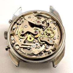
My first service, still a lot to learn and chasing low amplitude

-
Recently Browsing
- No registered users viewing this page.
-
Topics
-
-
Posts
-
 Interesting, thanks for the detailed post. I saw one of those Swiss Nano machines a while back in another youtube video from the Weiss Watch Company.
 -

-

-
 You're asking a pretty broad question and you didn't specify the machine but yes it's simple especially if you have the right machine. The question has problems but I'll take it as it is. Is it really that simple yes especially if you have the right machine. So in the video below he's making a screw and yes it really is that simple but pay attention to the machine it is not simple at all probably wasn't cheap but it is small it will probably fit in your garage. Unfortunately wouldn't fit in my garage as it's far too cluttered up with things. In the video he talks about making a screw and pay attention to the machine. The machine has lots and lots and lots of cutters and lots of things to do lots of machining all-in-one machine conceivably one step after another all programmable. If you look at his channel lots of CNC's stuff and there are several other videos related to this machine. He goes to the factory where they talk about it and show all the other machines they make in Switzerland. I did look up the specifications the machine I don't recall the price it's not going to cut wheels I think it has a maximum diameter around 11 mm basically it's really good for making small diameter watch parts. Then in one of the other videos he goes to a factory that used to make parts with waterpowered machinery been in business for 100 years and everything they now make is made with CNC machines including this one. What was interesting with the factory photo was that when they make some parts they can put them on a optical comparator comparator compares with whatever the reference is and the machine can be programmed to adjust its cutting to make sure everything is actually being made to specifications. Oh and then somewhere in all of this there was at least one picture of a balance staff can't have a CNC Swiss machine without making balance staffs. It would be really nice if we had pictures of the machine. Then yes if you look at the page for wheel cutting you can enter parameters and it will generate a G code but he left out things? Notice he has a picture of a complete wheel but the G code isn't making a complete wheel it's only cutting the gear teeth I don't see whereas the program for crossing out the spokes? Typically when you see people cutting gears once the teeth are cut most the time the spokes are cut by hand. Occasionally someone will mill them out but typically not with the program which seems strange if you have CNC capability for instance one of my friends fill it used to design assembly line equipment or things to make things. So his hobby was to continue to make tools to make things like clocks. Very interesting and clever clocks but his true fund was making the machines to make the clocks. Then machine is not controlled by G code like we would typically find today as the stepping motor controller he has was made a long time ago and the individual controllers used a textbased program. So the company had a editor you could write a program to cause each the stepping motors to do something. So basically once you figure out how to cut a gear he would just change the parameters for different size gears so here's an example of a gear as you can see we have the teeth and the spokes. Then we have a picture the machine which sucks because it would've been so much nicer if I could've taken a picture when it was cutting a gears so we can see things better. Then yes there is a worm gear stepping motor indexing this is a mini lathe and the indexing is at the end of the lathe head hiding. The basic operation of this machine would be brass sheet not cut to a specific diameter size not even round mounted on the machine. Then it turns and a milling cutter will cut the diameter. Then the gear would be cut with a gear cutter. The same mill cutter for the diameter although conceivably change the size I don't know but basically the same milling for cutting the outer diameter would be used to cut the spokes. I really can't remember how he did the center hole but whatever it was was very precise.
 -
 Yeah I know the site and the creator of it. the two video clips are good examples of the quicker method and a full tear down. the quick method will work in many cases. But not always and not for all the different movements. I strongly suggest to not bend the four tabs as was done in the first clip. Instead there are three tabs that insert into the top plate, Much saver way as to not break a tab.
-


Recommended Posts
Join the conversation
You can post now and register later. If you have an account, sign in now to post with your account.
Note: Your post will require moderator approval before it will be visible.