Jump to content

Recommended Posts

Posted (edited)

I'm working on a movement from a "clone" Omega that has a mix of Asian cloned 2824, 7750, and custom or unknown caliber parts. Parts are not available. The cannon pinion is loose and I don't know from which caliber (if any) it is based on. I measured it at 4.3mm high (including the driving wheel), so I don't think (?) it's a 2824 cannon pinion as the tallest (H6) is only 3.2mm tall, and I think that includes the driving wheel based on the schematics in the tech sheet.

So, if I can't source a replacement is there any way to tighten these? I would think it's not recommended to try and squeeze the two arms closer together as it may throw the wheel out of round. Can the distance between the arms be decreased by peening the arms where it contacts the cannon pinion? Or, I'm wondering if maybe the driving wheel alone could be swapped out, but I'd need to know for what caliber. Is there an easy way to tell by measuring the wheel?

20231019_113524-copy.jpg

Edited by GuyMontag
Posted
10 minutes ago, nevenbekriev said:

Just take the pinion out of the weel, turn the wheel upside down and then put back the pinion on

Interesting. How does that tighten the fitting between the wheel and the cannon pinion?

BTW, what is the best way to remove the pinion from the wheel without distorting the wheel?

Posted (edited)
56 minutes ago, GuyMontag said:

I'm working on a movement from a "clone" Omega that has a mix of Asian cloned 2824, 7750, and custom or unknown caliber parts. Parts are not available. The cannon pinion is loose and I don't know from which caliber (if any) it is based on. I measured it at 4.3mm high (including the driving wheel), so I don't think (?) it's a 2824 cannon pinion as the tallest (H6) is only 3.2mm tall, and I think that includes the driving wheel based on the schematics in the tech sheet.

So, if I can't source a replacement is there any way to tighten these? I would think it's not recommended to try and squeeze the two arms closer together as it may throw the wheel out of round. Can the distance between the arms be decreased by peening the arms where it contacts the cannon pinion? Or, I'm wondering if maybe the driving wheel alone could be swapped out, but I'd need to know for what caliber. Is there an easy way to tell by measuring the wheel?

20231019_113524-copy.jpg

You have highlighted why working on clone movements is a fruitless effort if something doesn't work quite right.

If it is an ETA driving wheel and cannon pinion, you would replace it as standard practice, rather than bodge it as suggested to you earlier. I'm confused about how removing it and then replacing it would have any effect on its tightness as no explanation was given. If anything it would make it looser, but hey! That's not to say it can't be done, but removing the cannon pinion from the driving wheel may very well distort the wheel badly. If it isn't distorted then the two 'arms' could be brought together, but judging how much and how tight is a bit of a guess until it goes together again. Again, replacing the cannon pinion could likely distort the wheel. Good luck with it!

19 minutes ago, GuyMontag said:

Interesting. How does that tighten the fitting between the wheel and the cannon pinion?

BTW, what is the best way to remove the pinion from the wheel without distorting the wheel?

I'm confused by that as well

Edited by Jon
  • Like 1
Posted

If the piece is pricy, best to replace with new one.

To repair, clean and roughen the groove of canon pinion with sand paper, if your lucky might works.


Posted
4 hours ago, HectorLooi said:

How about replacing it a Chinese clone cannon pinion?

Check it out! SG$2.83  32%OFF | 1/2/5PCS Replacement Watches Mechanical Movement 242 Cannon Pinion With Driving Wheel Spare Part Metal For ETA 2824-2 Tools
https://a.aliexpress.com/_mtlRUEU


I'm not sure that the part I need is a direct swap in from a 2824. Above I mentioned that my cannon pinion measures 4.3mm while none of the 2824 are above 3.2mm.

If I could find a part to swap in that would be my first choice but I don't know if this is a custom part or a clone of an existing cannon pinion.

Posted

You'll be surprised how easily these type of friction pinions come apart. Sometimes when the hour hand is tight, just using a presto hand remover will pop the pinion off with the hands.

I would hold the tube in a pinvise and carefully lift the wheel. It usually comes apart without much force. To fit the wheel back in, I just do the reverse.

  • Like 1
Posted (edited)
On 10/19/2023 at 10:34 PM, GuyMontag said:

Interesting. How does that tighten the fitting between the wheel and the cannon pinion?

BTW, what is the best way to remove the pinion from the wheel without distorting the wheel?

Well, The place of the pinion where the wheel sits is a little conical. That's why the wheel wears this way - conically - in other words - the size of the 'hole' is smaller on the one side than on the other. Turning the wheel makes two cones fit oposite, thus the normal tightness of the fitting is reached. Without need to tighten anything.

I am wondering, didn't You try what i said??? This is so simle and takes no more than a minute!

Edited by nevenbekriev
  • Like 1
Posted
2 hours ago, HectorLooi said:

Haha. Not recommended but works.

Like rinsing watch parts in Ronsonol. 🤣

I'ts like another post how to bend pin pallets to change the depth of escaping to the escape wheel. It's in one of  De Carle's books so it must be right. 

  • Haha 3
Posted
16 minutes ago, oldhippy said:

Yes I know. 

Haha to be fair three of us all thought it was a crazy idea trying to bend them , it didnt stop de carle writing a book with quite a few barmy tricks to try. 

44 minutes ago, HectorLooi said:

Maybe we should start a new post.

"Crazy things we do that work!" 🤣

Or "I saw it on YouTube, so it must be right!"

I do crazy things all the time at work, i just make sure nobody is around when i do them, saves me having to explain why it didnt work 😆

Posted (edited)
5 hours ago, nevenbekriev said:

Well, The place of the pinion where the wheel sits is a little conical. That's why the wheel wears this way - conically - in other words - the size of the 'hole' is smaller on the one side than on the other. Turning the wheel makes two cones fit oposite, thus the normal tightness of the fitting is reached. Without need to tighten anything.

I am wondering, didn't You try what i said??? This is so simle and takes no more than a minute!

That's what I'm going to try when I finish servicing. Parts are in the tray but I'm waiting on some winders as all of my arbors were too large for the inner coil (~ 2mm).

Edited by GuyMontag

Join the conversation

You can post now and register later. If you have an account, sign in now to post with your account.
Note: Your post will require moderator approval before it will be visible.

Guest
Reply to this topic...

×   Pasted as rich text.   Restore formatting

  Only 75 emoji are allowed.

×   Your link has been automatically embedded.   Display as a link instead

×   Your previous content has been restored.   Clear editor

×   You cannot paste images directly. Upload or insert images from URL.

  • Recently Browsing

    • No registered users viewing this page.
  • Topics

  • Posts

    • A helpful way in aid of assembly is to place all the wheels in their respective places, place to plate on the top and fit a couple of the nuts onto the pillars. This stops all the wheels wobbling about as they are lightly held by the plate, you can manoeuvre the pivots into their holes, using a tool , usually home made or can be bought on eBay. I made my own. As the pivots align and fall into place screw the nuts down a bit to keep up the tension on the plate untill all wheels are in place then tighten down sufficiently to keep the plate in place whilst checking the end shake on ALL wheels and their location when all is good only then tighten down the plate.
    • I'd say my Pultra 10 lathe. It is just so well made and everything fits so tightly together.
    • Welcome to the forum, enjoy. 
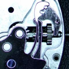
    • Yes, the specific old tools do exist, but may be having one is not needed as they are not cheap, and also You will be able to do without it well enough. My advice will be to use regular depthing tool and adjust it for the exact distance between pallet fork and escape wheel bearings from the watch. Then remove the shellac from the pallet that now doesn't pass the ew teeth and move this pallet in. Then put the pallet fork and ew on the depthing tool and check how they lock. They should not lock when the pallet is in, but You will little by little move the pallet out and locking will appear. Then move just an idea out for reliable work and apply shellac, then check if things are still the same. You have to observe where the teeth fall on the pallets - it must be just a little below the edge between impulse and rest planes. Then You must check how everything behaves in the movement This Potence tool is so ingenious, but actually, the traditional way to do the things is much more simple. Arrange the parts not on the pillar plate, but on the cover plate. Only the central wheel will remain on the pillar plate, secured by the cannon pinion.
    • There is a tool that was made for setting up and adjusting escapements of full plate watches.  There were two styles, the picture below shows both of them.  The lower tool held a movement plate and the vertical pointed rods were adjusted to hold the unsupported pivots of the lever and escape wheel.  There was also a version of this tool that had 3 adjustable safety centres so that the balance pivot could be supported by the tool :  The other version I’m aware of is the Boynton’s Escapement Matching and Examining Tool came as a set of two or three clamps that gripped the watch plate and held the safety centres for the pivots : These do turn up on eBay from time to time.  For some escapement work, you can set up the parts in a regular depthing tool, with the centres set according to the distance between the corresponding pivot holes on the movement.  I hope this helps, Mark
×
×
  • Create New...