Leaderboard


Popular Content
Showing content with the highest reputation on 02/06/18 in all areas
-
Here they are Sent from my iPhone using Tapatalk Pro1 point
-
I'd be pleased ...apologies if its is too much, but its hard to tell the story without telling the story. I wrote a 12 part series that appeared in Home Shop Machinist magazine on scraping - the build of the rotary lap was included in the how-to series so I have a inventory of build photos. The whole point was a way to achieve fast and perfect scraper sharpening. I haven't had that particular lathe in a long time - this must have been built 10 or 15 years ago. Anyway it started with a cheapo offshore bench grinder. The tricky bit is the way the laps mount. I made taper hubs for the rotor that are loctited on and turned in situ so the surfaces are perfectly concentric. These are a careful fit with cast iron disks (the laps) so the laps can be removed charged and remounted. The taper adds complexity but ensures minimal run out, not easy to otherwise achieve on something that has be taken off and remounted like this. Failure on that would lead to lots of vibration, possibly at a dangerous level as the disk are lot heavier than grinding wheels it was designed to carry. As it is, it runs very smoothly. The rests and frame are simple machining/fabrications. Here's some more photos of the build re the tapers....its tricky getting tapers to mate while also mating on a face, the process is a series of specific steps I'll gloss over slightly as its probably too tedious and OT for here. The laps start as 6" dia drop rough turning then I split the drop to get two disks The disks are rough turned, drilled, taper bored and mounting holes drilled and couterbored Note the outside the of disk get turned - I made arbor to fit the disks. Turn in situ on the shaft would not have been rigid enough and chatter would have resulted finished disk arbor It gets dialed in with the 4 jaw to perfect concentricity and the disk OD and face are machined before removing the arbor, the compound is dailed in to exactly on the taper - so the hubs end up a match - the roughed out hubs get cemented on the rotor and turned in situ on the lathe. The most difficult part is achieve the right mate on the both taper portion of the hub, and the back. thats pretty much it. the frame simple cut and braze and rests very basic machining stuff - not much more to tell other than whats visible in the complete unit1 point
-
As the mainspring barrel sits in the movement, notice which side the barrel cover is on. If it's on the top (not dial) side, then the spring is inserted/wound in a counter-clockwise direction (outward spiral to the left). If the barrel cover is on the dial side of the barrel, then the spring is wound in the opposite direction (outward spiral to the right). The barrel, no matter which side the spring is loaded from, rotates in a clockwise direction as viewed from the top (not dial) side. Does this make sense?1 point
-
lap charging. In that photo I'm use green diamond paste (iirc green = 10 micron) and a cast iron lap (not steel). It will put a mirror finish on the work. An old deep groove bearing with the inner race held in a vise grip (so the outer race can rotate) is used to press the diamond in the the cast iron. Put a pin head size bit of paste on the lap and roll it out with some downward pressure. A point here is the relative hardness of the surfaces. Cast iron is much softer than the hardened race so when the diamond is caught between them with a bit pressure, its embedded into the cast iron. If the race was the same or softer, the diamond would embed in it. Another thing that might not be appreciated is that the lap itself is not really touched by the work. Its surface becomes a cutting tool, the work comes into contact with bits of diamond, not the lap. That lap shown has been in use for 10 years and the cast iron surface is a flat as the day I made it - its not worn way by the work and the work doesn't really touch it. Hope that helps, ask away and i'll help if I can1 point
-
90 percent now working. 5 in the works. I have about 60 now. Sent from my iPhone using Tapatalk Pro1 point
-
Hi, welcome to this friendly forum. I don`t do very much now. It was always a hobby for me but I was lucky in getting some expert training and theory many years ago. There are some very good people here. Regards, Mike.1 point
-
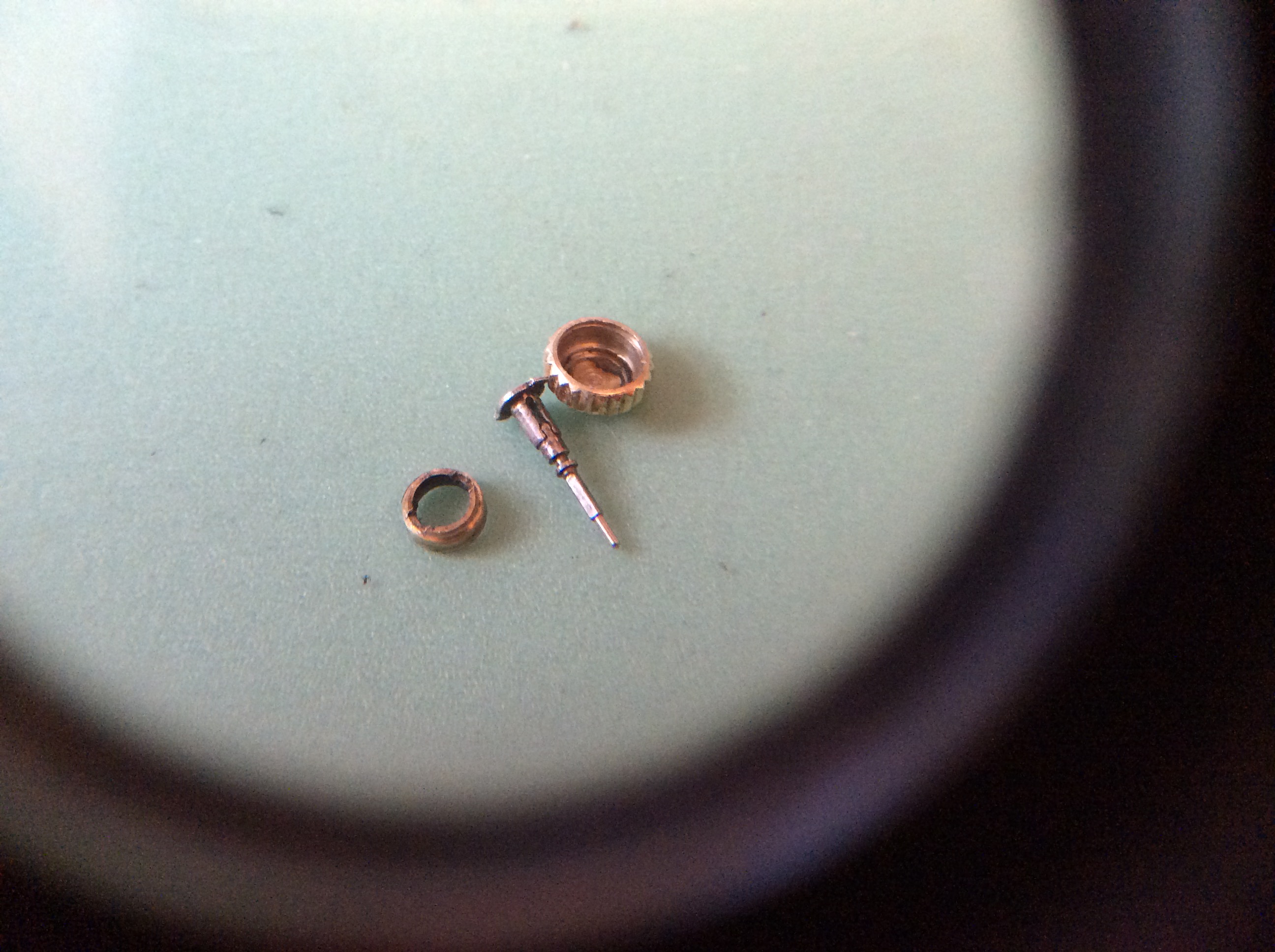
Well mystery solved, it was a split stem, in the end I just gave it a tug and 5he whole stem pulled out, it did not split and it damaged the clutch wheel in the process so I now need one of those.
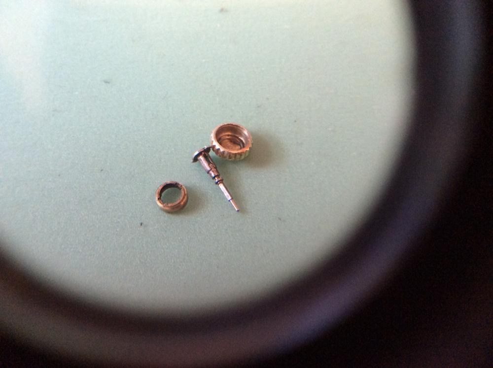 1 point
 -
From what I can tell from images on google it appears to be a press fit, I don't see any eccentric screws or clips. If still in doubt upload some pictures so we can take a look.1 point
-
some mechanics find it easer to read a book than watch a video. clock books are available, vin0 points