Leaderboard


Popular Content
Showing content with the highest reputation on 06/06/23 in Posts
-
Two facts were confused here, I am afraid: - a hole not staying/getting round - a hole wandering out of center, though round. It will get/ stay round, not oval, if you ream fully to the end (and was smaller before reaming). But it can wander from its true center - if it was oval, sidewards worn before - if you press more to one direction while reaming. You will produce bigger shavings in that direction and move the center then. One cutting edge is is used for canon drills, too, to produce long, accurate holes. The item moving with the reamer is normal, due to tolerances of the tool combination. It will do no harm if you let it move. Clamping the item would throw the produced hole out of size. Frank PS written before 2 new posts above3 points
-
I believe I heard someone say that the cylindrical part of the reamer should always go into the hole as well. I can't remember the rationale for it though, or if any was given. I understand that you are trying to understand the principles but as far as your jewelled pivot gauge is concerned it shouldn't really matter what the holes look like or where they are on the plate as long as the jewel sits securely and reasonably flat. So what you're saying is that we can't repair a damaged jewel hole by just using a Seitz jewelling tool, right? All we can do is open up a non-damaged hole when we don't have the correct size jewel That's valuable information to avoid going from worse to worse.3 points
-
It's rarely the mainspring. As a beginner I too was always over-concerned about the mainspring. It's more likely a problem with the barrel arbor, gear train, balance etc etc.2 points
-
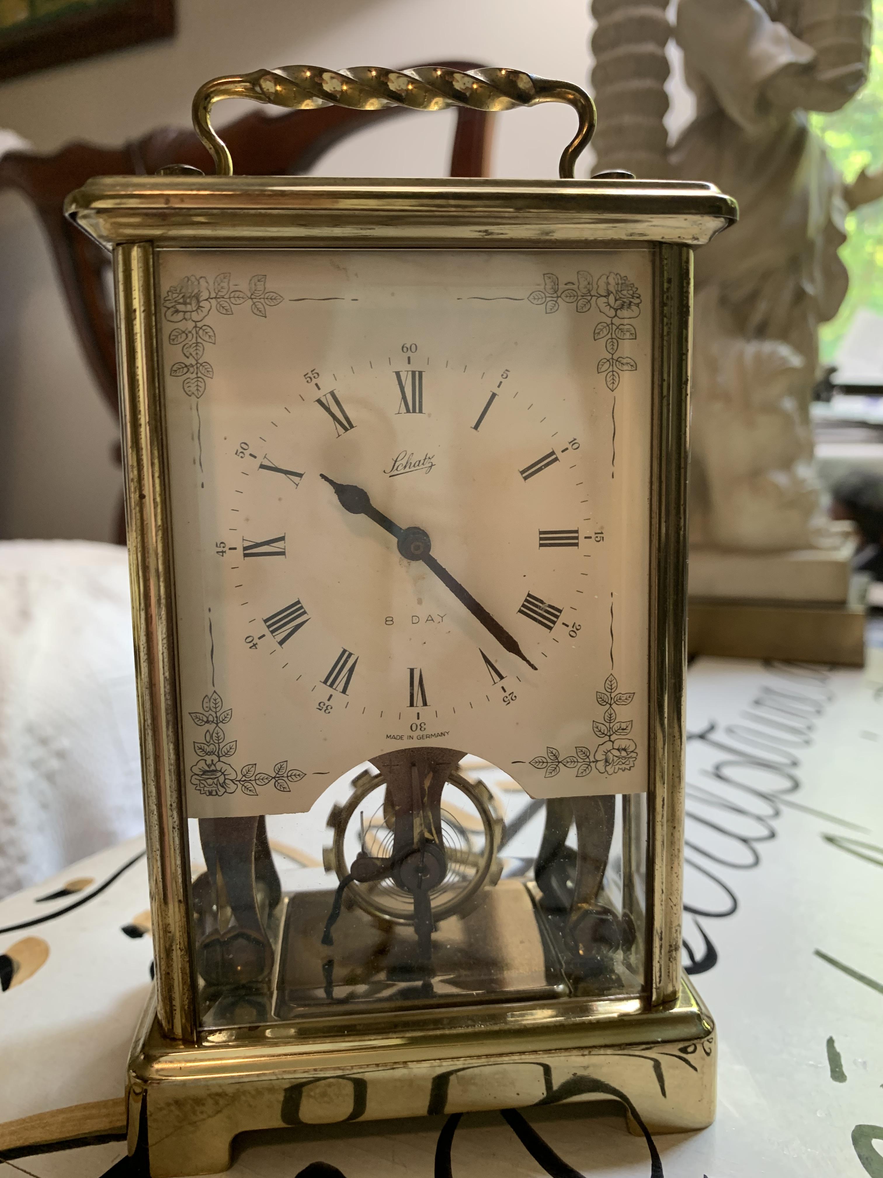
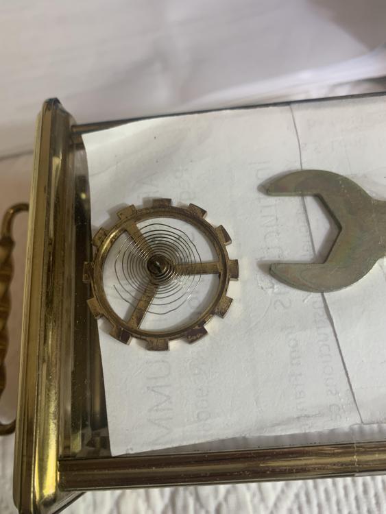
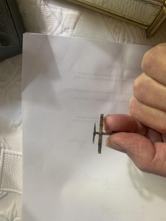
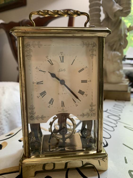
Success; it is running again. Your help is much appreciated. And I learned a lot. For one thing - I am no clockmaker and have a lot of respect for those who are. After repairing the hairspring tediously the first time, I installed the balance wheel and with tweezers finally got it to thread into the regulator stud - a very small hole. Tested and it absolutely would not run - at all. Then I noticed that the hairspring was all out of kilter again. Removed the balance wheel again and spent about seven hours on the hairspring for the second time. Reinstalled the balance wheel again, tested, and it did the same - would not run at all. Again noticed the hairspring was all out of kilter. So I went to Youtube and watched a video of a fellow removing a Westclox balance wheel; it is found as "Westclox balance wheel remove and install." I then realized that I have been deforming the hairspring by pulling it through the regulator tab with tweezers and into the regulator stud - that if the hairspring is coiled properly it should thread into both. And that solved everything. Reluctantly I removed the balance wheel again and this time with less enthusiasm reformed the hairspring again (see picture). I spent about four hours on the hairspring this time and it is significantly poorer than my other two efforts. But it threaded into the regulator tab and was less than 1 mm away from threading perfectly into the regulator stud hole. (Even though I did not remove the hairspring from the balance wheel, after reinstallation I noticed that the pallet pin(?) was oriented at the bottom and would not click the paddle(?) so the minute hand would not advance. Referring to the youtube video, I placed a small screwdriver blade in the collet crack and rotated the balance wheel so that the pallet pin is on the top. That worked.) When I wound and started the clock again, it would only run for about 50 clicks. After experimenting with the regulator some ten to fifteen times back and forth, it seemed to take life with the regulator (surprisingly) at exactly the twelve o'clock position. It has now run for seventeen hours and I call it good. The hairspring is no longer beautiful but seems to be good enough. To everyone, thank you again for your help. I have now breathed life into this old clock after many years and have a much greater appreciation for the craftsmanship of the maker.
 2 points
 -
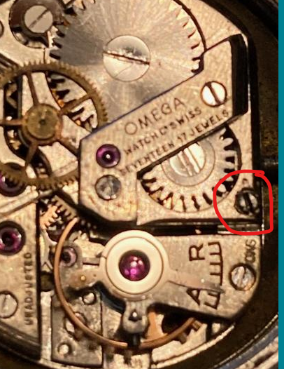
I removed the balance and under was R13.5SC, Thanks!2 points
-
Isn't this the set lever screw ?
 2 points
 -
I tend to agree with Jon that the only real way to know your hole is on location and round is to use a faceplate in the lathe. But, many, many watchmakers have reamed holes for jewels with their Seitz or Chatons SA or Favorite or Horia etc. tools successfully as well. It's one thing if you're opening up a hole 0.10mm, another if you're opening say a hole for a barrel arbor pivot a full mm to fit a bushing. As has been observed, the reamers don't necessarily turn concentrically with the spindle of the tool; this can lead to the reamer cutting oversize if the part being reamed is held rigidly. If the part is allowed to float, as Endeavor did, the reamer will probably follow the original hole and cut to size. The reamer will make a round hole, and should be run right up to the cylindrical part (and some oil used). But if working on an oval hole, the location will almost certainly be an average of the original hole center and the new center of the oval. This will be an improvement of the prior state, but not ideal. To add to all the confusion, there are different types of reamers used by different manufacturers. Favorite uses 5 sided tapered reamers, look like short little cutting broaches, that end at a cylinder of the correct size. Seitz and Chatons SA use single lip reamers. Horia offers both, calling the 5 sided ones cutting broaches and the single lip ones smoothing broaches. I've used them all, and found that the single lip ones from Chatons SA cut the best, and run quite true in the spindle. I still let the part float so the reamer follows the hole as well as it can. But most of the time, I do the work in the lathe. I have a rather large (for watchmakers) lathe set up permanently for faceplate work, and use optical centering like Jon mentions. It really takes just a moment to center up and open up a hole! And I bore it right to size, but I have plug gages that make checking very simple.2 points
-
Hmm... One should really be getting one while they're still affordable. My impression is that all other quality tools have increased in price significantly in recent years while lathes still feel somewhat reasonably priced. Anyway, I still have a long way to go to get the most out of my current tool collection. Yes, they're tapered, and I would suspect you're 100 per cent right. Is that an accessory for the Seitz jewelling tool? EDIT: Found the "face plate" in the Seitz jewelling manual, which is used to hold small parts, such as the pallet cock, when reaming.2 points
-
I don’t have any reamers yet to verify so this is something of a guess. I suspect the the reamers are tapered to give a gradual cut and the top portion that is cyndrical finishes off to give a taper free clean hole. Which could still be out of round if the taper section has created a wide enough oval. There is a jewelling faceplate that can clamp this might minimise the effect of the wander Sounds feasible unless the part being reamed can be held completely rigid and the reamer and its spindle had no slop whatsoever. The tolerances on the tool and accessories would need to super minimal, in reality i bet far from the accuracy of a lathe. So like jon said the reamer is going to follow the shape of the hole, i would say through the tolerances of the tooling. Time to buy a lathe watchie, come on you know you want one2 points
-
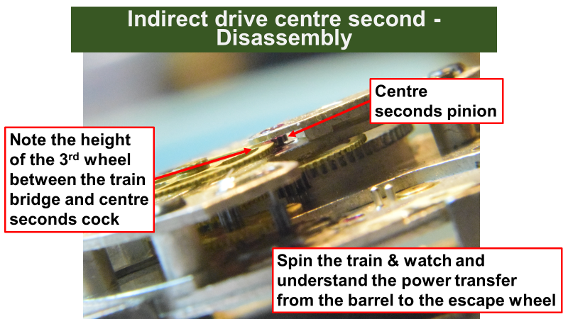
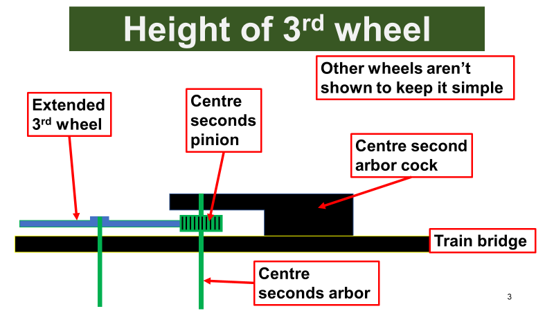
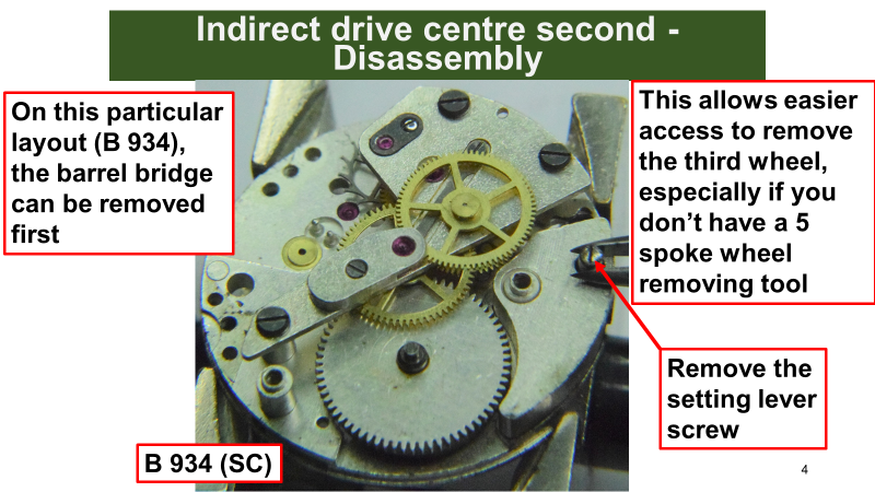
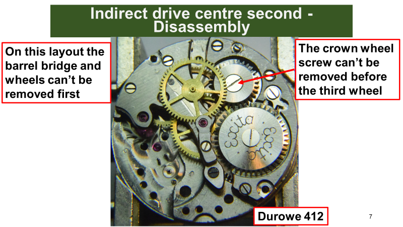
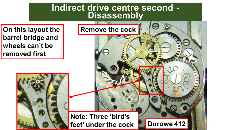
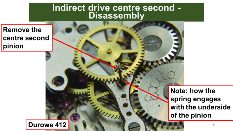
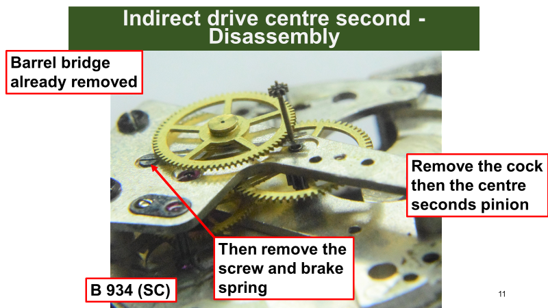
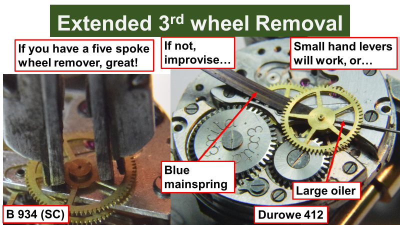
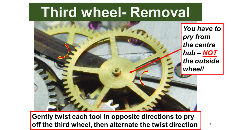
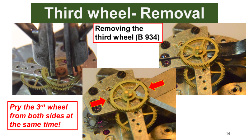
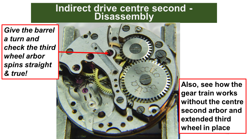
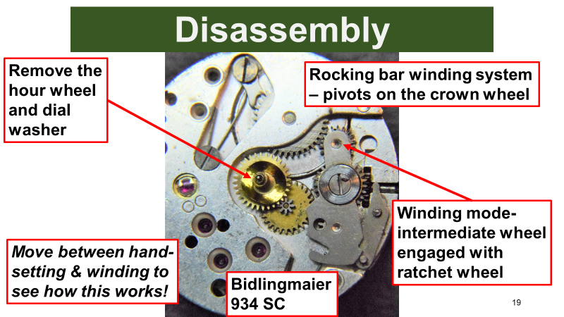
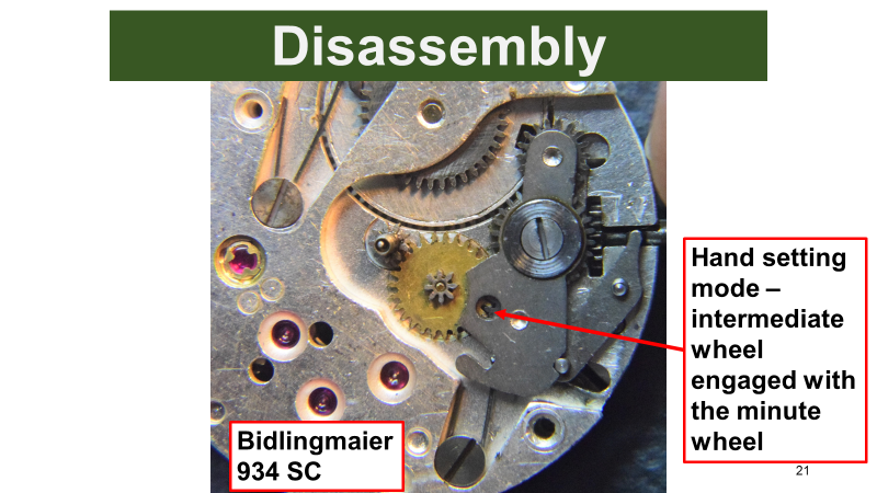
I posted some of these slides from a lesson I take on an indirectly driven sweep second movement. I hope it help anyone. I really should post the set of lessons on a sweep seconds movement sometime soon. The Bifora (Bidlingmaier) 934 has a great rocking bar winding system, which isn't usual to see, as seen in the last two slides
 2 points
 -
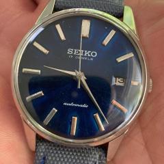
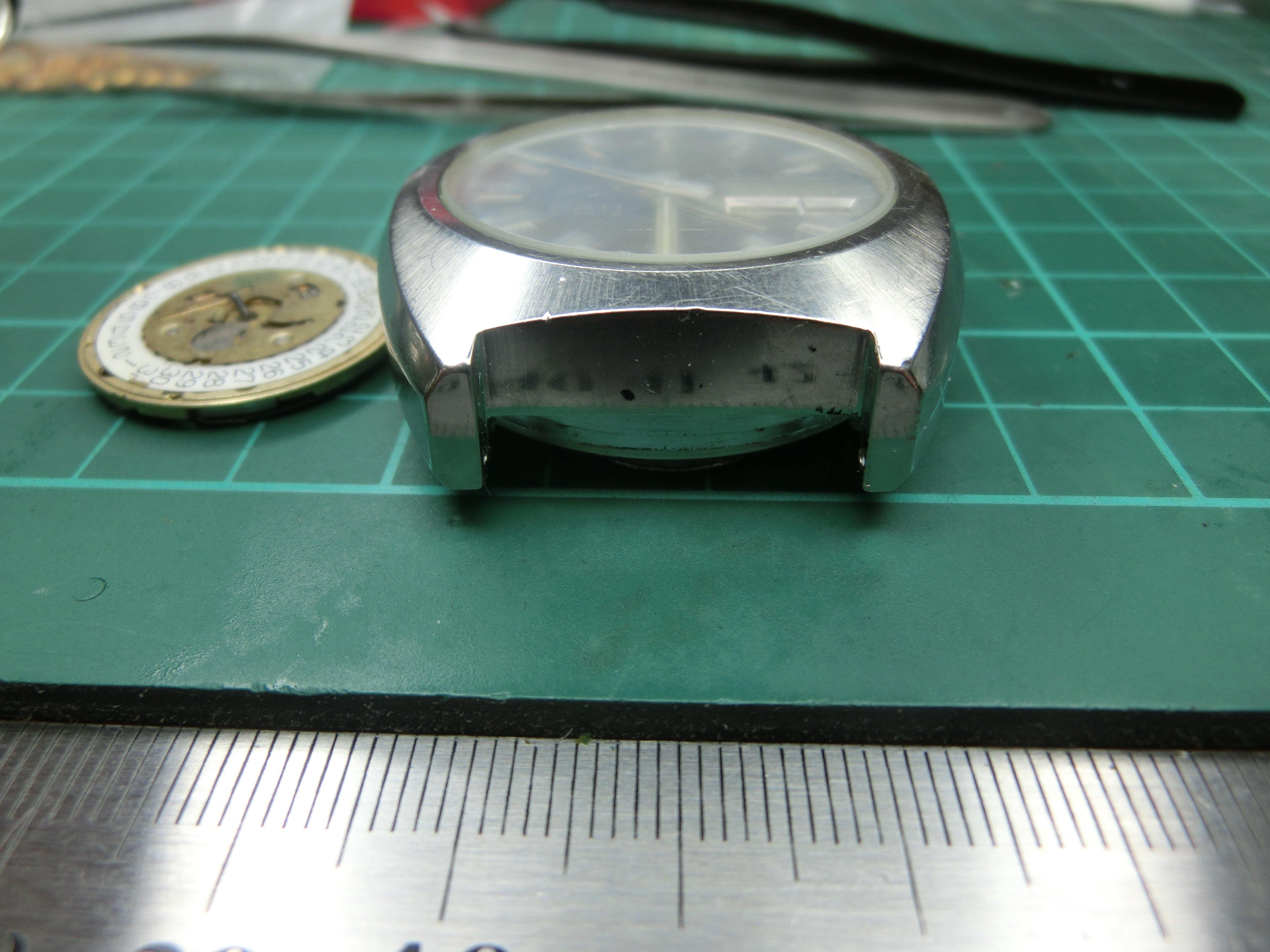
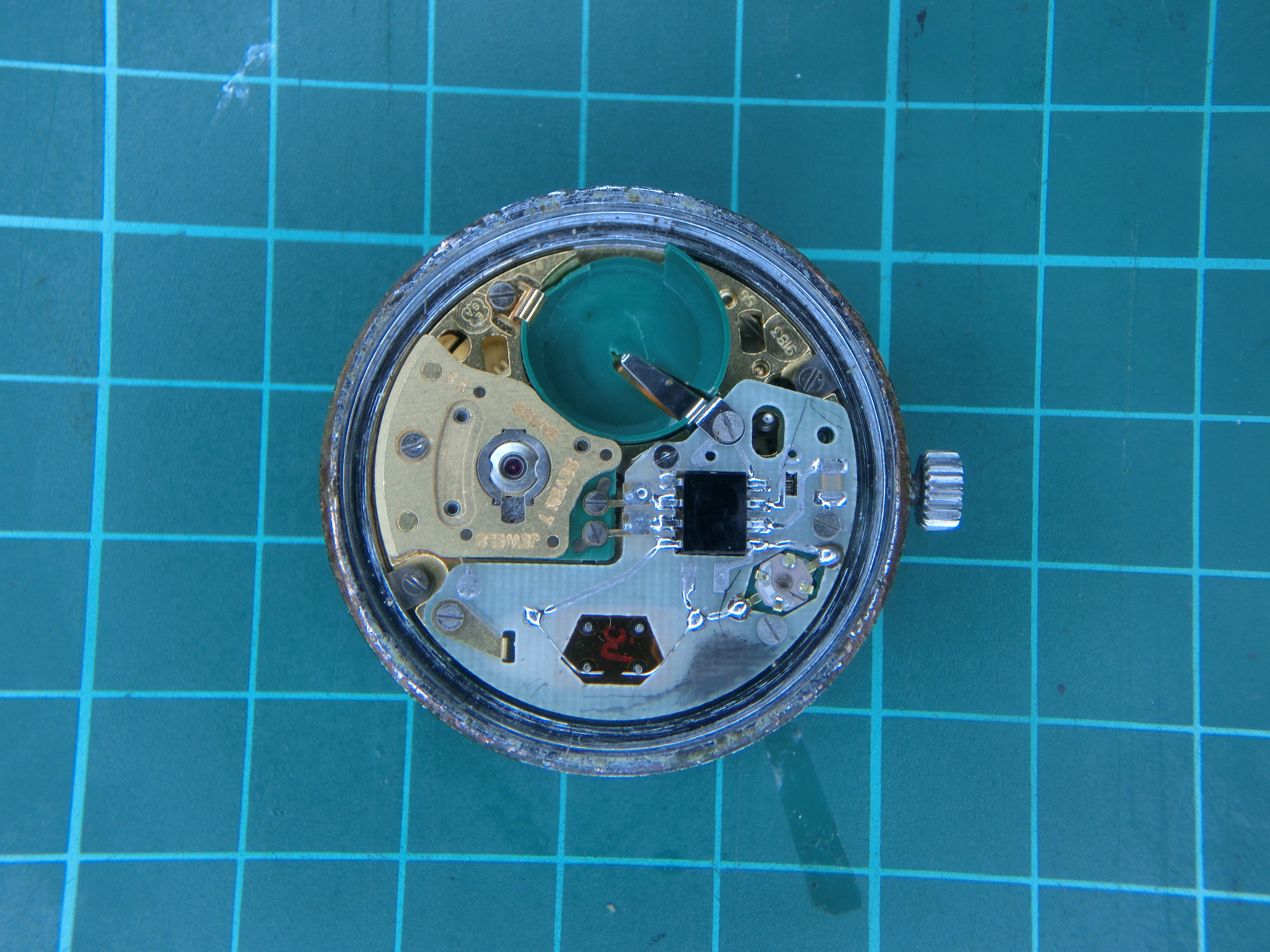
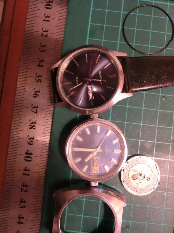
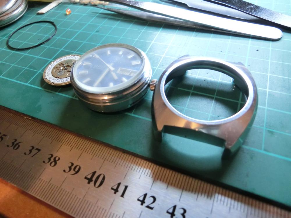
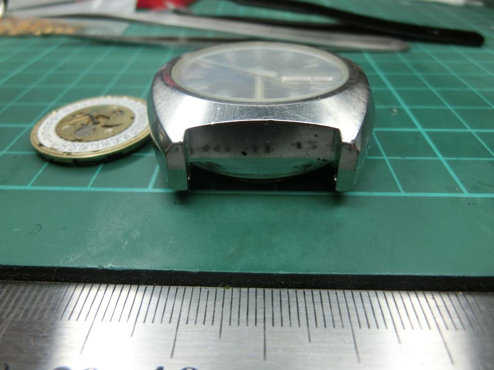
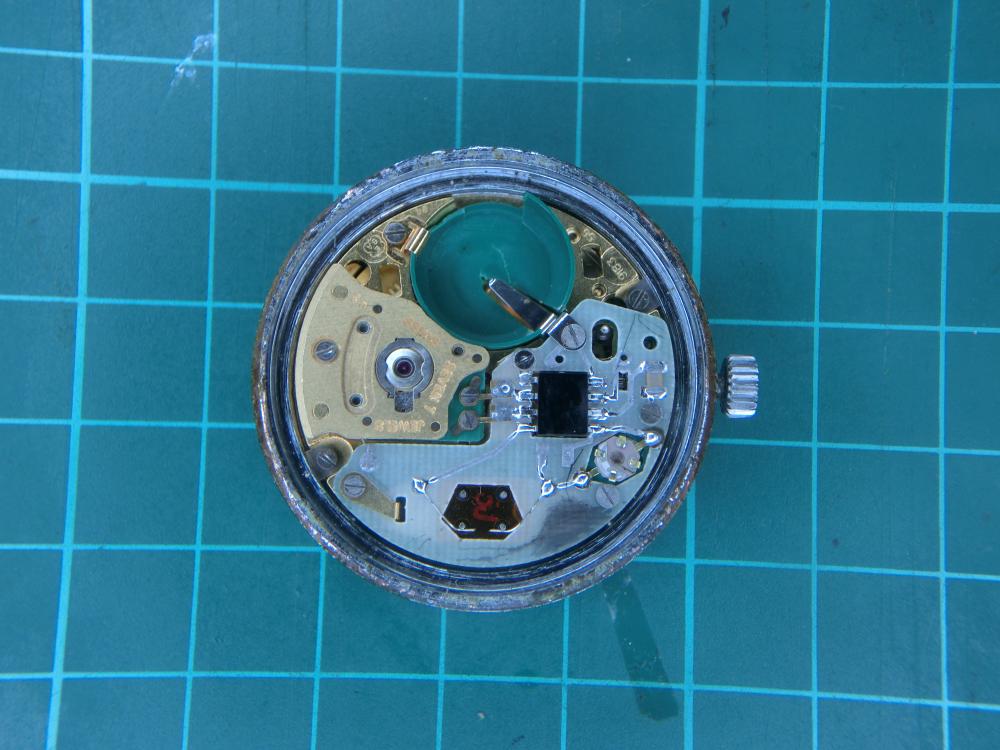
The ESAQuartz 1501 - (ESA 9183 quartz mechanism) - "Verity" arrived and got a quick tear down and inspection. Its a pretty substantial watch. Some might say robust. The case is multipart, and the outer case snugs into the inner one using a rubber gasket, which had turned into the kind of black tarry liquid that is often the fate of gaskets from that period. The actual case back was secured with another gasket, which had turned rock hard and broke when removed, and the battery cover had a third gasket, which seems to be fine. There may be an O ring in the crown tube, but I didn't get that far. Much cleaning later... just for the record, black tarry liquefied gaskets are removable with olive oil, and I felt it was safe to handle without my biohazard suit. The mechanism is completely frozen, and the crown wont move, so a full strip down is in order. Not tonight though. I'll save that for another day. Here you can see it next to a modern quartz mechanism for comparison, and also next to my current daily "beater" watch. which rather ironically is actually larger than the "Verity". All that effort and research to make smaller and smaller quartz mechanisms and fashions dictate that watches got bigger, not smaller. Its a strange world we live in. I must say, the ESAQuartz 1501, and indeed the whole watch is fantastically over engineered, and probably cost a small fortune when new. If you would like to see a good tear-down of the ESAQuartz 1501 /ESA 9183 @Marcdid a good write up about it here. https://watchmender.wordpress.com/2019/03/04/smiths-astral-quartz-esa-9183/
 1 point
 -
Yes, I understand. I didn't just stick them in an arbitrary position though and leave them that way. I had to readjust a number of times until it was about 1/3 of the thickness of the impulse jewel (what Mr H Fried explains in The Watch Repairer's Manual on pp 208 - 210). Possibly I didn't get it right, but it was not just an arbitrary setting that I just selected. I don't have a very accurate way to measure it other than with just my eyes via the microscope though. If there is a better way to ensure it is only 1/3, then please let me know. That being said... should I post some pictures of the exit and entry stones when the escape tooth locks on them?1 point
-
Without professional knowledge we can over complicate something that is in fact quite simple. Its a watch, a micro mechanical machine with many moving parts so everything about it must be complicated, so i will look for a complicated answer to the problem . I always start with the basics and try to use logic working from part to part to part as no moving part works alone. All connections are important and a lot of issues are found within connections. A step back and a break can help disengage confusion and complication. Just how i think and might make no sense whatsoever to anyone else1 point
-
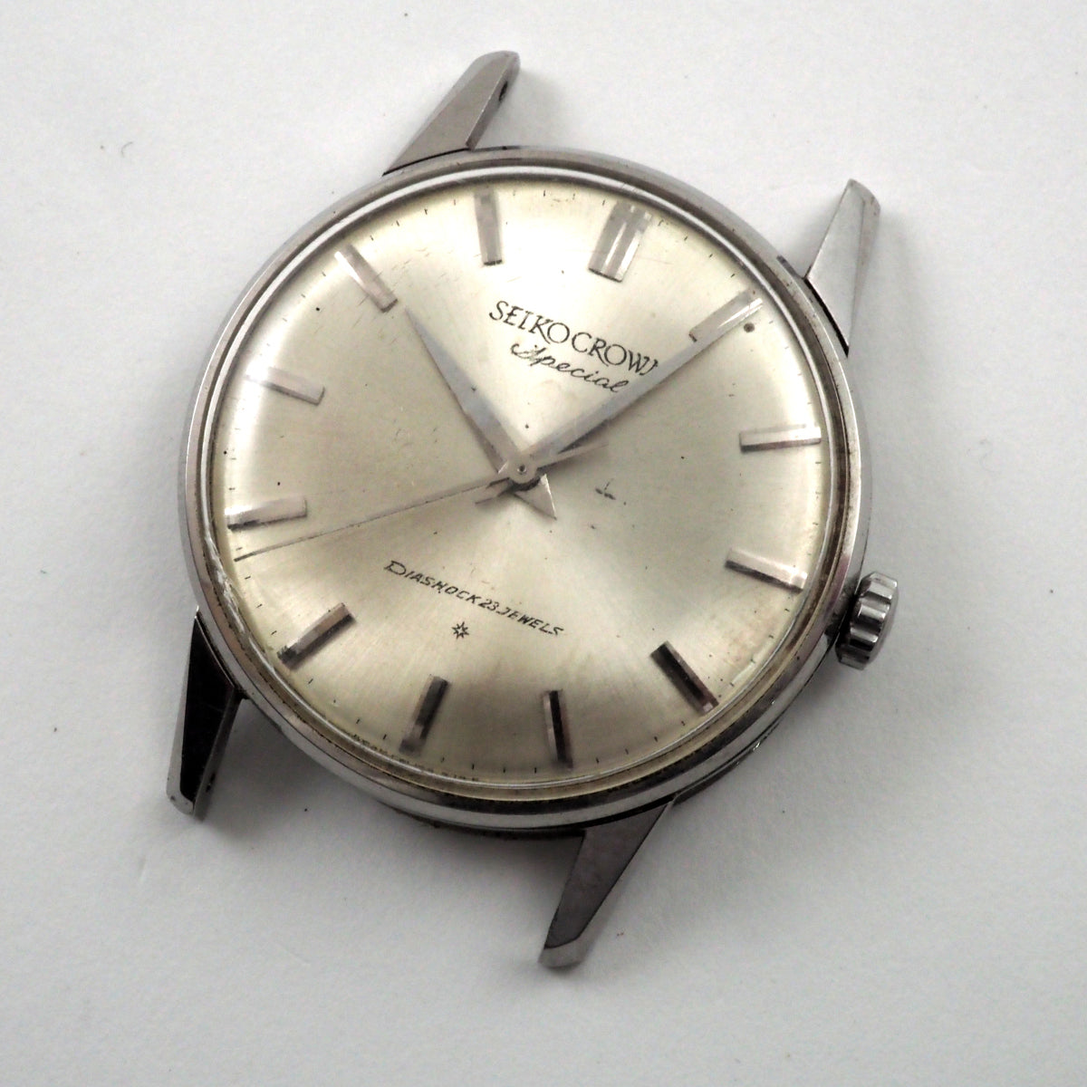
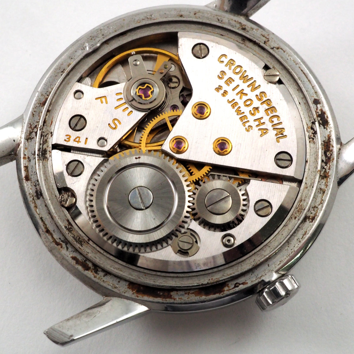
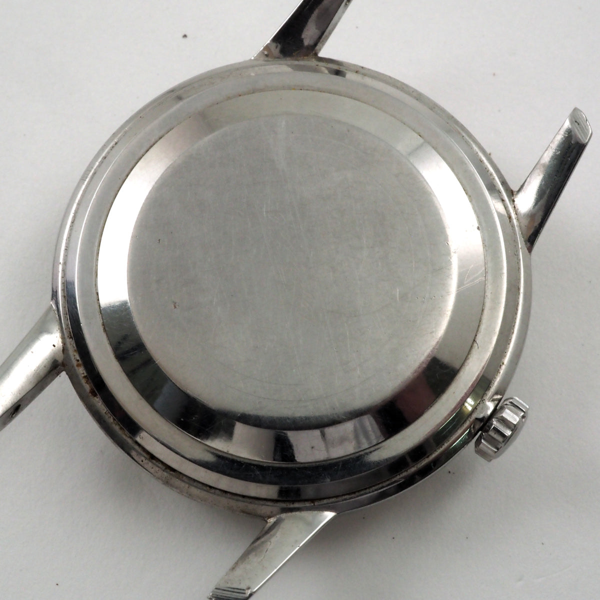
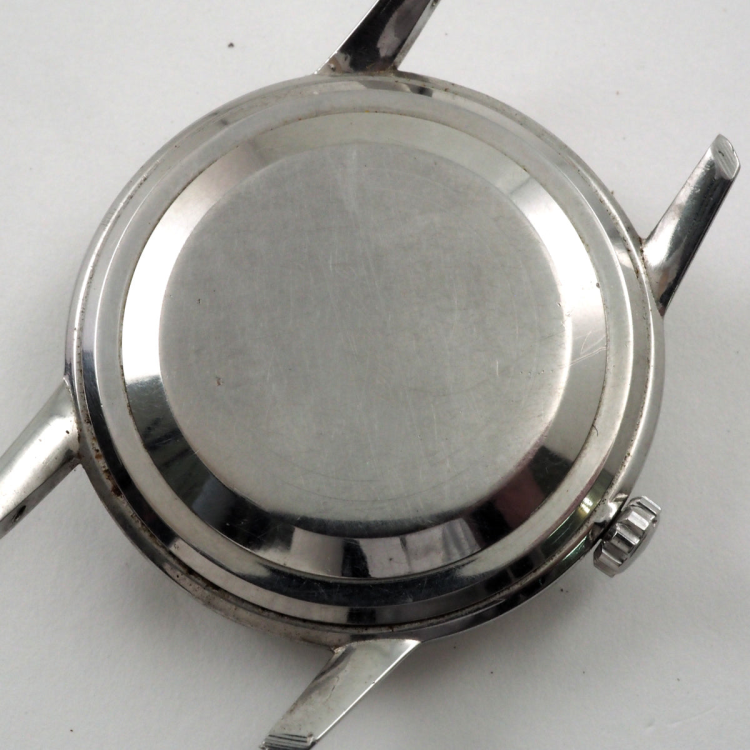
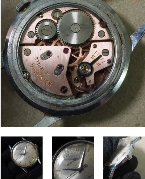
What no pictures the movement? Yes Seiko has all sorts of interesting movements I was looking at the vintage manual wind. Then as a little late to post my pictures here because it was supposed to come Wednesday so would've been in the mail when I'm posting but it showed up yesterday on the porch. DHL from Japan definitely faster than US mail which is probably why had arrived early. Then I did pay attention to the case and dial but I really wanted a manual wind movement. Specifically a specific type of manual wind movement like this 23 jewels. If you look at a lot of the grand Seiko's there at the very top of the food chain but this watch is just a little ways down not is nicely finished missing to jewels different regulator but very similar. So in other words my cheap version of a grand Seiko not quite as grand but still nice. Then since it arrived it appears to be in the mainspring is broken pushing on the center wheel it takes often run sell if I'm lucky that's all I'm going to need. The only other minor troubling thing that bothered me was the picture of the back shows it to look blank? But was looking up other watches like this the pictures showed writing. Then in real life looking at it the writing is there but it is extremely faint as there's a heck of a lot of scratches. Makes me wonder how long somebody wore this watch. Then the second watch didn't save any individual pictures I just snipped out the overall images so not the best. There is more of an afterthought because shipping is per package and it seems a bit high for one watch and this was on sale so I just thought it made things look better if I'm getting two watches. Then yes the dial looks a bit not the best in several locations and the crystal should be changed. Then it is wound up nice and tight. Because as far as I got fixed I haven't figured out how the back comes off yet doesn't appear to be in a place to pry it up but the image is very clearly show that it does come off even though it looks like a frontloading watch?


 1 point
 -
That looks better for a first time. For what its worth I started back in the early 70's as an apprentice I did a 5 year apprenticeship then another 2 years as an improver learning all about watches and clocks this included making certain parts for watches and clocks.1 point
-
We need to work on your Timing machine diagnostic skills. The beat error is unacceptable then the amplitude is extremely unacceptable. In other words this watch has a serious problem beyond stopping. Then ideally you should do at least two positions dial down and maybe crown down for wristwatch so we can see the difference. You want to try an experiment? Wind the watch up put it on the timing machine change to crown down position take a picture forest as I really do like to see the picture. Wait give it some time look at it every half hour so until it comes to a stop. This group has a amplitude obsession. Somebody is probably having a heart attack right now over that amplitude you have. Usually for this group to minimum acceptable at the end of 24 hours would be 200° it will vary for the watches though some Omega's Can go down to 160° but that's a really nice watch. Then on this group the obsession is aiming for 300 which is silly but 170 for a fully wound up watch you have a serious problem. If you were to allow the watch to run in its current condition you'll notice the amplitude should be dropping off really really fast and the reason your stopping is you're running out of power so there is some serious problems here. In other words it's probably not the mainspring barrel that there's something else going on.1 point
-
Notice how the screw looks visually different then the plates screws? Then typically this is the location if there was a screw you would find the screw. But I see that I was composing when you already replied but just for future reference use of the school be physically smaller oriole Bidwill different style and usually in the location You'll notice up the above link work list and shows the other variations of lists the number you have is the old number system they switch to a new number system so they go to look for parts shall have to use the new system because the old system basically doesn't exist. In related to your part number I did find your parts list you will note there is no service manual. Typically parts lists exist service manuals do not. At least not on websites that are trying to sell parts. So you'll notice that yours is the 250 for some parts in the base calibers 240. Then sweep wheel be careful how you remove that ideally should have a sweep wheel removing tool. 1475_Omega 240.pdf 1483_Omega 250.pdf1 point
-
I got the stem out, it was just a little stuck. Hands and Dial came off easy
 1 point
 -
Photos please.1 point
-
Thank you for your introduction and welcome to this friendly forum. We all look forward to your contributions and continued involvement.1 point
-
Hello and welcome from England.1 point
-
I know a fellow who does a lot of Omega work, and does top notch work, and he regularly opens the barrel hole in the bridge for a bushing, just using the Seitz reamers. He says he's had no problems with the hole wandering off center. I think if you're very careful and let the part move with the reamer it should be ok... but I personally would still do it in the lathe. I'm not sure where he gets his bushings or what sizes are available (I make all my bushings), but if you open it to the smallest OD possible for a bushing, and find that the barrel now sits tilted, the hole can still be rectified in the lathe and a slightly larger bushing fitted.1 point
-
Ha Ha Ha your learning.1 point
-
The holes were made with a normal HSS drill and I've no idea how cylindrical the holes were before reaming? But at least a HSS-drill has two opposite cutting edges, whereas a Seitz reamer hasn't. Well, it has, but only one side cuts. In my observation above, it may well be that the holes were oval to start with and that is what caused the radial movement of the plate? But, if we assume that the to be reamed hole is perfectly cylindrical, what concerns me is that those Seitz reamers do have only one side which cuts, namely the one in the direction of the rotation. The reamer gets "supported" against the borehole by the other side of the reamer (the non-working cutting edge). Since it cuts with only one cutting edge, I still try to get my head around it whether the reamer stays centered or cuts an asymmetrical hole. And if it cuts an asymmetrical hole, does that than gets corrected by the very end of the reamer where the reamers cutting edges go over into the cylindrical part of the reamer?1 point
-
Balance screw cutters are more readily available.1 point
-
Hey, sorry for the delayed response. And thanks for your input. I've thought many times about doing plating. Sadly my workshop is quite small with terrible ventilation. As luck would have it, there was a RW Tango on eBay! Case was scratched but the bezel was mint! Tension relieved at the tune of fifty quid, Never polishing those cases again!1 point
-
If a hole is out of round (ovalled), then using a Seitz or Horia reamer will not bring it back to round, even if half the hole is a good shape, as the reamer will always wander, therefore the hole won't be in the correct position and in the case of a barrel bridge or mainplate, it only needs to be out by 0.01 mm and the barrel will rub on the bridge and mainplate, so you can see how critical it is to getting the hole central. I have found the only way that really works every time is using a centring microscope on the lathe. I use a Skoal centring microscope from Korea (Costs about £300). This is able to find the hole centre and bore it out using a micro carbide boring bar. The hole is now totally circular, now you can use the Seitz or Horia reamers to open up the hole to 0.01 smaller than the bush or jewel. How the centring microscope works is by finding the exact trajectory of the outside of the hole. See the video in this link. It shows a Rolex oscillating weight that needs bushing, but the principle is the same: https://www.instagram.com/p/CszBfc7LPL4/ Clocks don't have this problem, as the tolerances aren't so fine as a watch movement1 point
-
Secondhand pivot cutters on ebay.1 point
-
Sounds like the reamers are wandering off center slightly, they're not balanced like a drill bit. , seems like an odd design shape. I cant say i understand the geometry of how they cut , i just suppose they should work .1 point
-
Nice tip! I tend to put it on a staking block with the hub inside a hole and judge what is high and what is low then transfer the wheel onto a piece of soft wood or even thick leather with a small hole in to accommodate the hub and push down on the high spots whilst keeping the wheel flat, but I think I'll try your way next time.1 point
-
Great vid. Straight to the point. Nice! I would put a slight flat on the side of the punches near the tips after annealing the tips, then drill through the side so they look like your last pic with holes in the sides. You'll need a V block and clamps to hold the work still and a precision bench press drill with some decent tungsten carbide drill bits. Then you'll find removing the broken off staffs maybe a little easier. You'll then need to harden and temper the tips again afterwards. Jobs a good 'un then. Or, you could turn some replacements on your lathe (if you have one) from some tool steel and harden and temper them with holes in the sides. I always have a supply of tool steel to make new stakes/punches and various tools. Here's some hand levers made to BHI specs... https://www.instagram.com/p/CpTjbxujGrP/1 point
-
Well that was an interesting little game. I set the wheel up in a horia type jewelling tool using a stump that nicely fitted the hub of one side and a jewel pusher that fitted the rivet on the opposite side of the drive wheel. This gave a nice even free wheeling wheel as tight or as loose as i wanted . I needed an index to work to as the bend was actually only slight ( which now leads me back to a possible bent pivot as well ) i decided a physical sacrifice was called for, so a very small nick in the nail of my forefinger and pressed up against the stump served rather well. Held up at eye level with plenty of light and a x10 loupe, just pushing past horizonal to straighen. Did it work ? Bloody right it did, not perfect but much better than it was.Nicklesilver you're a diamond great tip. Now to check for a bent pivot. I see these all the time on ebay, now i have an excuse to buy one And i thought i was the king of commas1 point
-
I've never used my reamers, but I saw a video where the hole was gradually reamed out selecting a larger and larger reamer. Very little material was removed with each reamer. It could also be that you need to use a bit of oil to smooth the process. Well, not even sure I understand the problem, but thought my reply at least wouldn't be harmful!?1 point
-
I acquired an L&R Master off eBay months back. It was dated 1954. It looked tired and after receiving it ran really poorly. So, I embarked on a rebuilding project. I am writing this because I found some sources for parts and services that may be useful to others, and it had taken me a long time (I’m talking many months) to find them all and get the work done. Link to pictures of before and after are attached at the end. Thanks to all on the forums and other sites for info, diagrams, and pics that helped me along the way. I cant recall where I got everything so a general thanks! The process was as follows (to help those taking this on): · Took the whole thing apart and stripped the paint down to the bare aluminum. I ground off some bad casting bumps while it was stripped. · I tried to crinkle paint it myself with VHT Wrinkle Paint but just couldn’t get it right, so I stripped it again and decided to send it out to have the body (including the motor housing) powder coated. So, the motor had to be completely disassembled before sending for powder coating. · All parts I was reusing were cleaned and polished where needed. So, you really need to have abrasives and both a workshop polishing wheel and Dremel. · The rheostat was not smooth and would cause the motor to jump speeds. But turned out it was just dirty with hard carbon build up so a good cleaning and some gentle scraping of the contacts and it was fine with smooth resistance all the way through the range. I also hit it with some very fine sandpaper (1200+ grit) lightly then cleaned with acetone. · Trying to get the rheostat knob off it crumbled into small pieces, but I found a good one on eBay. The knob as well as the motor brush housings are made of Bakelite on these old machines, and it doesn’t polish well nor necessarily hold up after about 70 years. · The heating resistor was good. Resistance was tested and was as marked. So cleaned it up. · The light bulb socket was good so just cleaning needed. Bad bulb but I found bulbs to fit on the internet and bought a box of #41 2.5V E10 base. · Then there was the motor. OMG. It ran but rattled, buzzed, and didn’t always turn. Bearings, wiring (I am lucky I didn’t fry myself when I turned it on after receiving it), and some burnt out armature winding wires on the rotor itself would cause it to not always start. Also cracked wire going into the stators. Finally, I decided to try to have it rebuilt. Very hard to find a company that rebuilds these Fractional Horsepower Motors. After searching for what seemed months, I found a company in California that would rebuild the armature and stator. · The brushes themselves were good and easy to replace if necessary. But one of the brush holders was cracked. I found a company that made brush holders that almost fit (larger by just about 1/32” with some slight enlarging of the motor housing brush holder hole. Drilled it out to 1/2” they fit perfectly. · I added a fuse and an IEC plug to the back. There is very little room on the back so finding an IEC outlet that fit was an effort. When getting new switches, I decided to get an On-Off-On switch for the motor Forward-Reverse. It’s normally an On-On switch. I didn’t want to rely on the rheostat to stop the motor. So I can leave it on a setting and switch the motor off. I also use a switched power line. I just never liked the fact you cant fully turn off all power to the entire unit given there are liquids and electricity in close vicinity of each other. · Grounded the whole unit of course. · The jars are original but had no covers so purchased on eBay both screw on and lay on replacements from someone that makes them via 3D printing. They are not as nice as the originals but work well and are lower cost and new. · The impeller had a crack, but I was able to repair it by brazing the crack and filing it smooth. You can easily braze aluminum carefully using an aluminum brazing rod and propane torch. · I did all the wiring and soldering myself. Those courses in collage in electronics helped Fitting the wires into the motor housing is a real challenge if you don’t have an original pic of the inside. Someone had already been inside the motor and the wiring was a real mess. Thanks to others on this and other web sites where I found wiring diagrams and wiring photos of the underside of the unit. · I used rubber coated wire between the motor top and the main tube because it just seemed softer and more flexible compared to some vinyl or PVC coated wires and that moves when moving the motor to the jars. The one thing I didn’t do is try to renew the motor and control panel labels. I have seen some others that look like they were able to do it but for me with the lettering and all it is just too detailed to paint by hand, so I just cleaned them and gave them a clear coat to protect them. Note that I did find a company www.dyna-graphics.com that could create duplicate overlays with all the L&R lettering, etc. (industrial decals) that could be applied to the control panel. Normally used for electronic control panels. But they had a minimum purchase, and I didn’t want to spend the money. Bottomline it was a long process and the motor rebuild was expensive. But with all spent its about what you might pay for one online that has been rebuilt like new and normally you don’t get a like new motor. Here is a list of companies that I used for parts and repair: · Gundy Powder Coating - Bayshore New York · Eurton Electric - Whittier, California. They rebuilt the rotor, armature, and stator (I put it back together myself and pushed on new bearings and fit the brush holders). · Motor Bearings - MiMotion https://www.motion.com/ Brand: MRC (SKF) Size MFR#: R6ZZ. The existing bearings were marked making it easier to replace. · Brush Holders - Phoenix Electric Manufacturing Co. (the bad part is they have a minimum order size. They come as a set, and you must buy 10 sets minimum. Each set includes the following parts: Part #1520-BC-660-895 (the holder), Part #AE-51-TP (the screw cap). · Switches – Gaynor Toggle Switches got them on eBay. Any good toggles should work ok. · Heater Light Bulbs - #41 2.5V Miniature Light Bulbs with E10 Base (purchased from Bulbtown.com but available multiple places). · Jar Covers – eBay sellers, 3D Printed. Link to Photos: https://1drv.ms/f/s!ArzY7G4e4SiEhe5TWmrNvCMc7vV9AA?e=TsAh9E Thanks bob1 point