Leaderboard


Popular Content
Showing content with the highest reputation on 04/03/18 in Posts
-
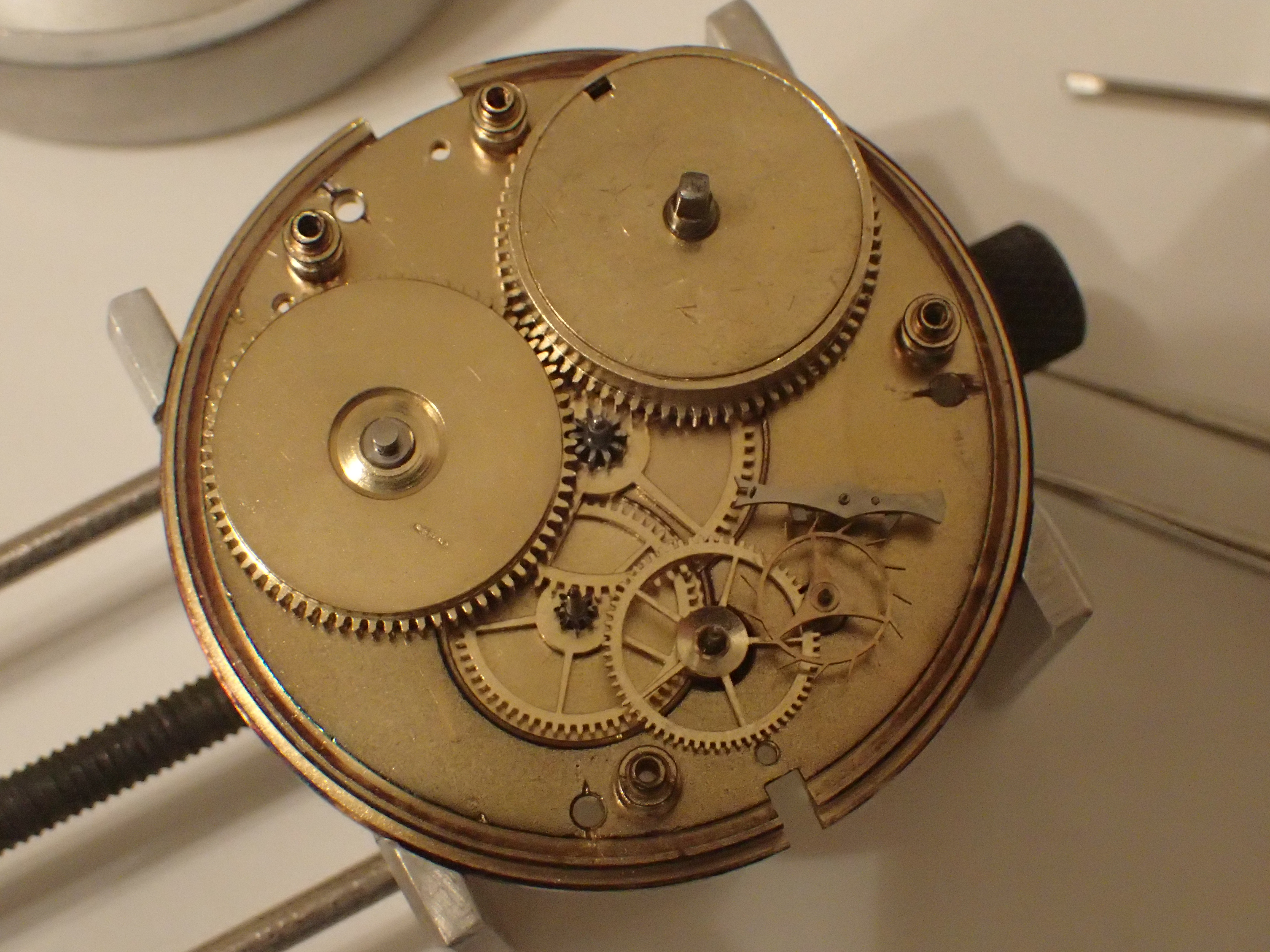
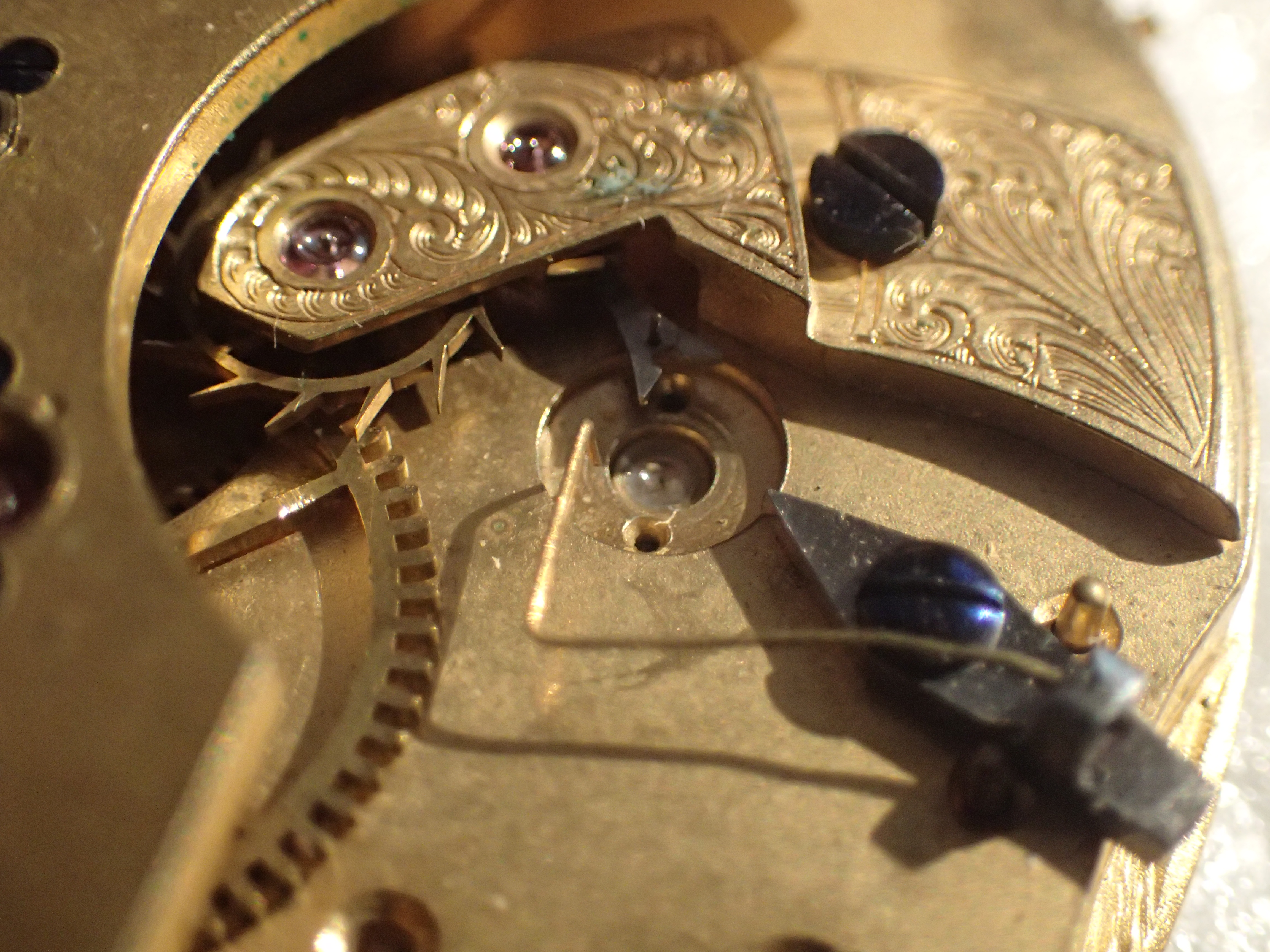
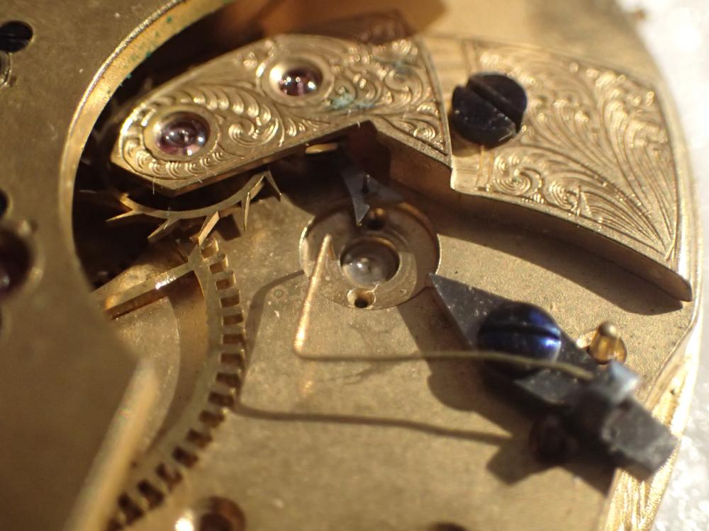
What you have is an indirect centre seconds configuration where the third wheel has an extended staff that comes up through the bridge to the back of the movement. An intermediate centre seconds drive wheel is friction fit onto the extended staff which couples with the centre seconds pinion. you will probably find there is a friction spring sitting on top of the centre seconds pinion to control the inevitable stutter that these design suffer from. This was the how all centre seconds configurations were executed when centre seconds first became a thing. It's a perfectly good way to achieve centre seconds without bu$$ering about too much with the rest of the movement but it has a couple of drawbacks. The stuttering is one of them, the other is it makes the movement quite thick. Anyway, the circular plate that you refer to is not a separate part, it is a thickening of the hub of the intermediate wheel in order to provide enough meat for a competent friction fit on the staff. There is a Presto tool specifically designed for removing these, and I have also seen some very nice pullers that people have made, but a pair of very thin levers or blades usually does the trick if you are careful. And you do have to be careful. The extended staff does not take kindly to anything other than a perfectly vertical lift; cant the wheel off of erpendicular to the staff and the staff will snap. Reinstall using a staking tool to keep everything nice and true.2 points
-
The red circled rectangle in the picture above, looks like a flexible Piezo Vibration Sensor, such as: https://www.sparkfun.com/products/9196 Here is the technical manual: https://www.sparkfun.com/datasheets/Sensors/Flex/MSI-techman.pdf I glanced through all 86 pages, no sample amplifier; but maybe its not necessary? Here is a sample Arduino circuit: https://learn.sparkfun.com/tutorials/piezo-vibration-sensor-hookup-guide Here is how to build a knock circuit: http://www.learningaboutelectronics.com/Articles/Piezo-knock-sensor-circuit.php Now that I see that, it makes sense. We don't want a microphone for all the reasons related in this thread. We want a knock sensor that feels vibrations and responds to them.1 point
-
That's why you have to close the hole to less than the diameter of the pivot and broach out, keeping the hole as round as possible. This work is not fine horology. As Oldhippy would say " Its more like Blacksmithing. " But you can also misalign when Bushing, requires a bit of practice. Sent from my SM-G920F using Tapatalk1 point
-
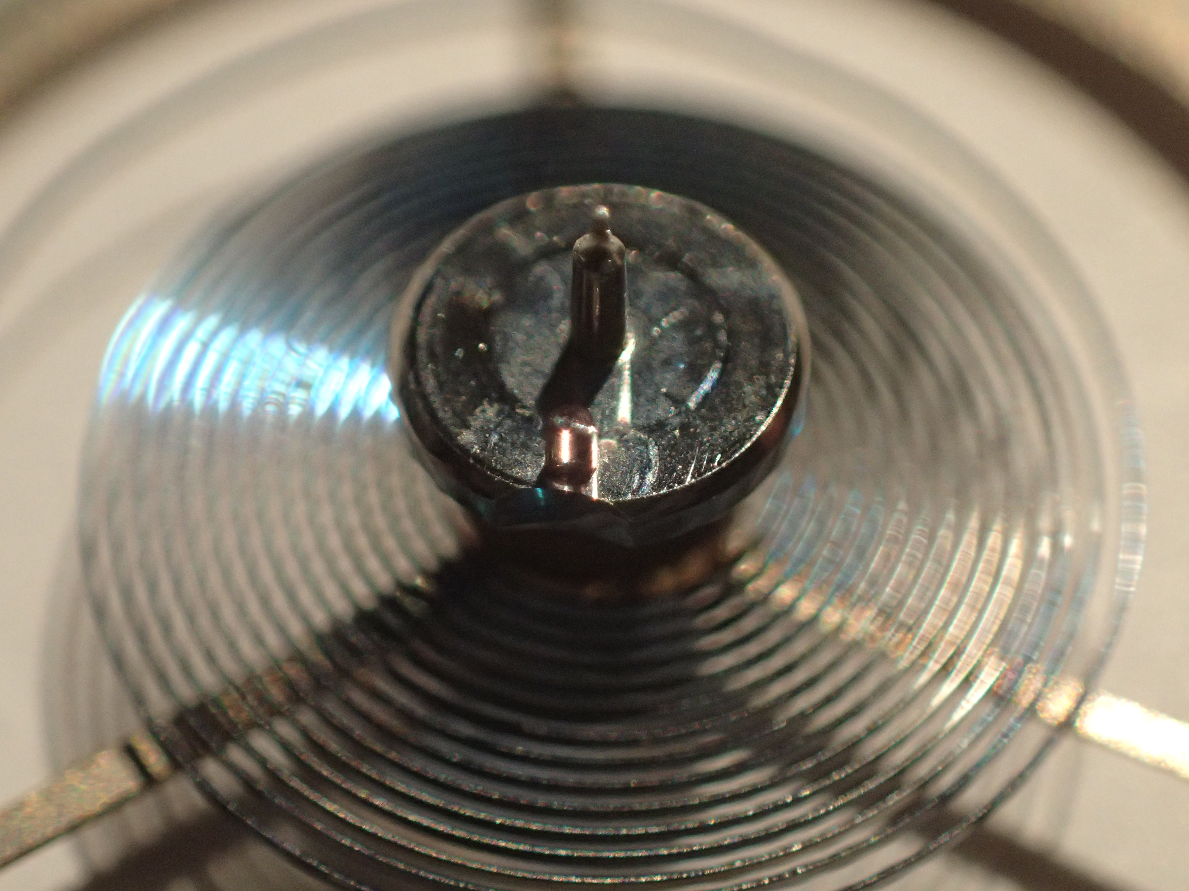
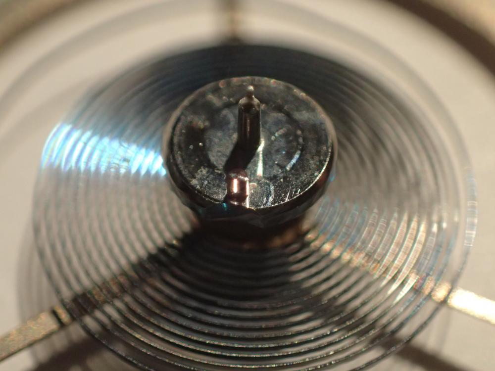
Here’s another photo with the centre jewel removed for clarity. Please note the beryllium copper leaf spring (slotted to accept the seconds shaft) with pinion on the top. Sent from my iPhone using Tapatalk1 point
-
An interesting question indeed! This is speculation on my part as I don't actually know, but I don't think that "lift angle" has quite the same meaning on these balance wheel electronics as it does on conventional mechanical movements. In a conventional mechanical movement energy is delivered to the balance from the escape wheel, via the pallet fork and impulse pin. The lift angle is the angle of arc through which the balance wheel rotates whilst it is receiving energy from the pallet, or the angle of rotation in which the impulse pin is in contact with the pallet fork (same thing). In an electronic balance wheel movement the power goes the other way. Energy is supplied to the balance wheel by the energised coils acting on the wheel mounted magnets. The balance transfers this energy to the pallet fork which then pushes round the teeth on the escape wheel thus delivering energy into the wheel train. If you compare the escape wheel from your Elnix to one from a conventional mechanical you will see that the teeth are a completely different shape to allow for the reversing of the direction of power transfer. You could argue that "lift angle" still has the same meaning as it is still the angle of rotation of the balance wheel through which energy is being transfered between the balance and the escape wheel. However, whether or not it makes the correct set of sounds for a timing machine to make sense of......??? I would try it out and see what it says. I suspect that it will be able to give you meaningful data for beat rate, beat error, and daily rate, but I'm not sure that I would have a lot of confidence in the amplitude reading. Even if it did give you accurate amplitude data, does it actually have the same significance as for a pure mechanical?1 point
-
There is a really good exploration of the evolution of centre seconds here; http://www.timezone.com/2002/09/24/the-pursuit-of-center-seconds-part-1/1 point
-
Personally I've always called this a sweep wheel. It's frictions on as others have said above it also has an up and a down so pay attention after he remove it. So the tool mentioned above I have another link showing how it's used. It also comes in a different number of fingers apparently there is different arm crossing so you needed tool that correspond to the number of arms you have. Then the tool found At the second link comes in three different sizes color-coded. All you do with this is slide this gently under the wheel rotate and lifts the wheel up. However you lift the wheel up make sure you lifted straight you do not want to bend the post that it's on. http://www.drsjewelry.com/cgi-bin/LTT1.pl?Sub-NSP=Removesandhandpress&Description-NSP=PRESTONo3SWEEPWHEELREMOVERBERGEON&template=1LVC&method=perfect http://www.julesborel.com/products/tools-hand-tools-hand-removers/bergeon-6016-wheel-remover-1-2mm1 point
-
Where did you get the new spring? Years ago on ebay from Argentinia1 point
-
I have seen the many times on watches where it is the seconds wheel, driving the seconds shaft pinion. Please see attached example of one on my bench now. The wheel is a friction fit and I use two long modelling blades to act as a lever. Hope this helps? Sent from my iPhone using Tapatalk1 point
-
I've got a Olympus TG-4. It's got a "microscope" mode that allows really close shots. They seem very good. I've not set up lighting on any of these - they are done either with background room lighting or a Ikea bendy led desk lamp. I'm also hand holding the camera so that add shake. With a stand and proper lighting you could get some cracking shots.

 1 point
 -
I’ve just watched your video right through. It is very awkward trying to clean a movement without a proper cleaning machine. The mainspring repair is ok providing the screw does not rub against the spring. What types of oil did you use? The action of the balance is very poor, what about the time keeping. With such a powerful m/spring, when it is run down that balance will hardly rotate. I would check the whole escapement for old oil and make sure the jewels are spotless. It would have been a good idea to have assembled the train and tested before putting in the pallets. Good luck. Are you going to video the up-date when sorting out the balance? I do hope so.1 point
-
Sent from my iPhone using Tapatalk Pro1 point