Leaderboard


Popular Content
Showing content with the highest reputation on 06/12/16 in Posts
-
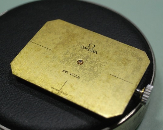
I've been looking for an Omega as an everyday watch and being a great fan of the quartz wrist watch, because I require great accuracy. Not having great wealth and the apparent cost of such a watch. For a decent second hand model with paperwork your looking around £1000. Would I be happy wearing it, incase it got scratched! So I decided to build my own. I didn't fancy attempting to buy a fake of the Internet with a cheap movement. Partly the fear of going to such a site and paying with my card and then having my bank account emptied or the proceeds of the purchase being used in the underworld of crime. So I started looking for the parts and trying to keep the costs to an acceptable level. Which were as follows :- Original Seamaster dial: £106 Movement : ETA 255.462 £140 Watch case: £32 (Could not find one with a helium escape valve) Watch hands £5 (Went for more traditional hands as I don't really like the more sporty hands) Watch strap: £10 Total cost = £293 See pic below. I've tried to keep it in the spirit of the original Sent from my SM-G900F using Tapatalk1 point
-
I recently acquired a Waltham 0/size 1907 grade 165 pocket watch. When attempting to remove the dial, one of the 3 dial screws was rusted firm in place. In order to get this stubborn screw out I purchased some Hoppes #9 Gun Bore Cleaner from amazon. I used a small glass dropper to carefully apply some solution to the screw from 2 directions. I placed some directly into the screw hole on the side of the plate, and I also applied some directly to the dial foot visible from the plate. I was a bit concerned about potential damage to the keyless and motion work since they were both still in place beneath the dial. I needed to reapply the solution for each of 2 days. So after a full 48 hour soak, I was able to very easily remove the screw with a normal screwdriver. Thankfully there was no damage to the other components of the watch. I immediately disassembled the remaining components and ran them through the ultrasonic to remove the solution. I still recommend caution using this solution with other types of metals.... Hope this helps someone else!
 1 point
 -
this is for balance hole jewels, and you don't need a jewellers set tool to put these back; except if damaged train jewel don't need to be removed.1 point
-
yikes! that one has seen better days. it looks like someone wore it and put it away wet - literally. i have a lot of mido parts, but they're all automatic. i do have some peseux parts (although i don;t know exactly what parts they are), so contact me for your needs.1 point
-
Why do you want to replace it ? don't see any problem in your picture. It's look like a 23j Waltham so it's a valuable watch. As oldhippy says changing a jewel is not so obvious ; second the method described is for friction jewels (the modern type) and these Waltham used jewels in setting (the jewel is burnished in the setting) . In the old time they were plenty of available parts and the watchmakers can replace easily the setting. Nowadays finding a replacement is a hard job. In my opinion, replacing the setting by a friction jewel, even if it can be done, is not a good idea as this will drop the value of this watch. The best option is to find a donor movement.1 point
-
Hi Guys, thanks to everyone who has helped me with this question, Bob, I did take the mainspring apart, no winder though so referring back to my 'Watch Repairing as a Hobby book' by D W Fletcher I managed to use a pin vice to wind in back into the barrel. noirrac1j, thank you for the images with them I managed to put the watch back together and it ran for about 4 hours then stopped, as far as I am concerned that is a victory for me. All I need to do now is strip it again and see why it now keeps stoping after about 3 or 4 minutes? Anyway, once again thanks to everyone on the forum with out your help over the past few months I would have a large box of parts instead on watches. Den1 point
-
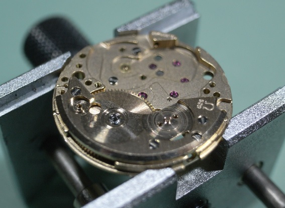
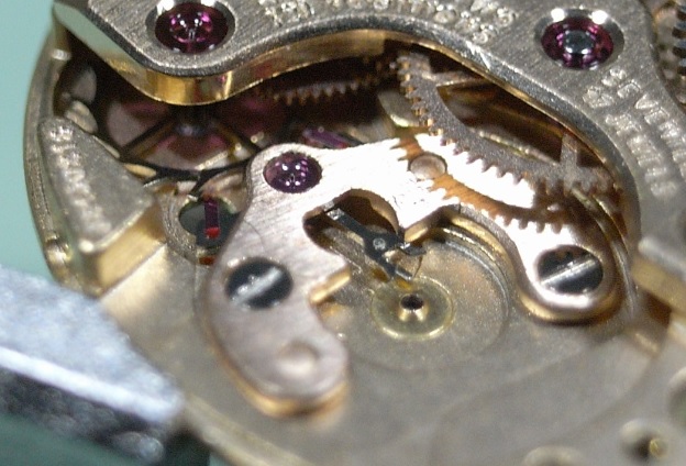
Dial side has some different parts to accommodate the day wheel. The calendar gear, and its spring set up is completely different to that of the 2824-2.1 point
-
Believe it or not, I just got around to fixing this. I didn't have a drift, but I found some brass rod stock at the hardware store. The locking wheel did not want to come out. Someone had tightened its set screw so hard that a burr had formed. I whacked that with a punch a couple of times until I could just get it out. Then I filed the burr down, cleaned, lubricated, and reassembled. Everything is smooth as butter now. Thanks again Geo!
 1 point
 -
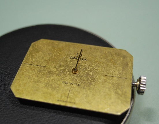
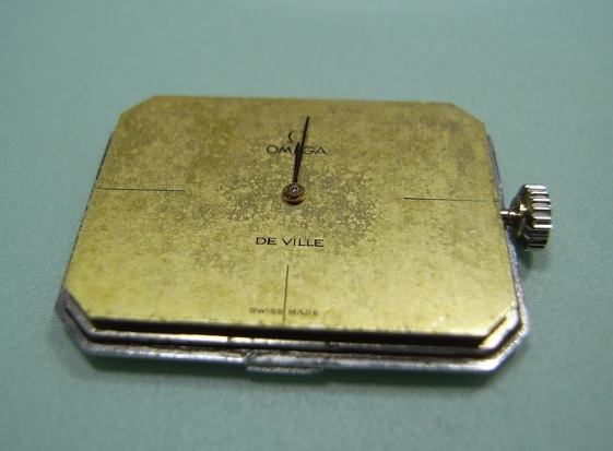
That black line in the shape of the glass is a gasket.1 point
-
nice tool reference. pricy thu1 point
-
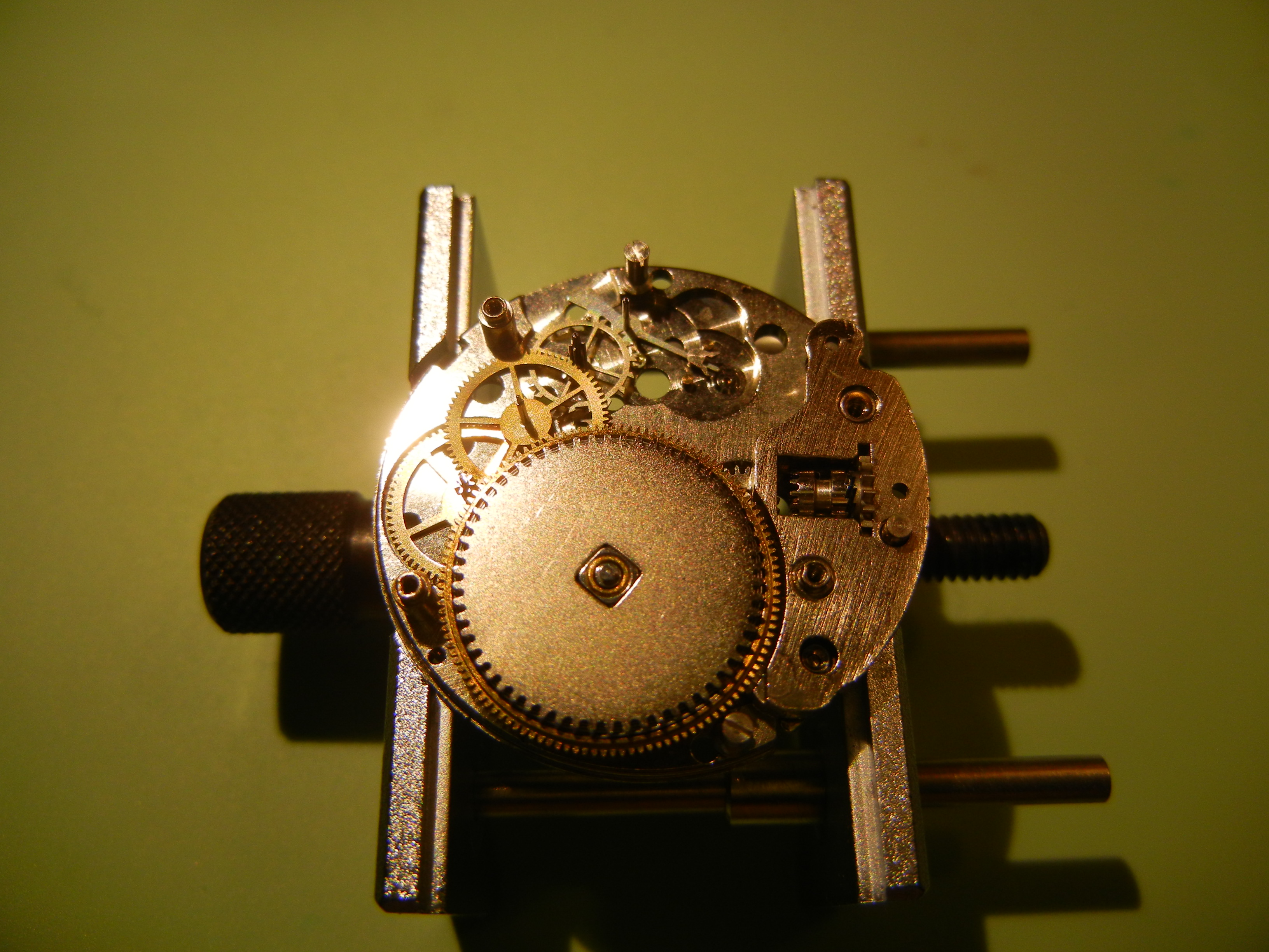
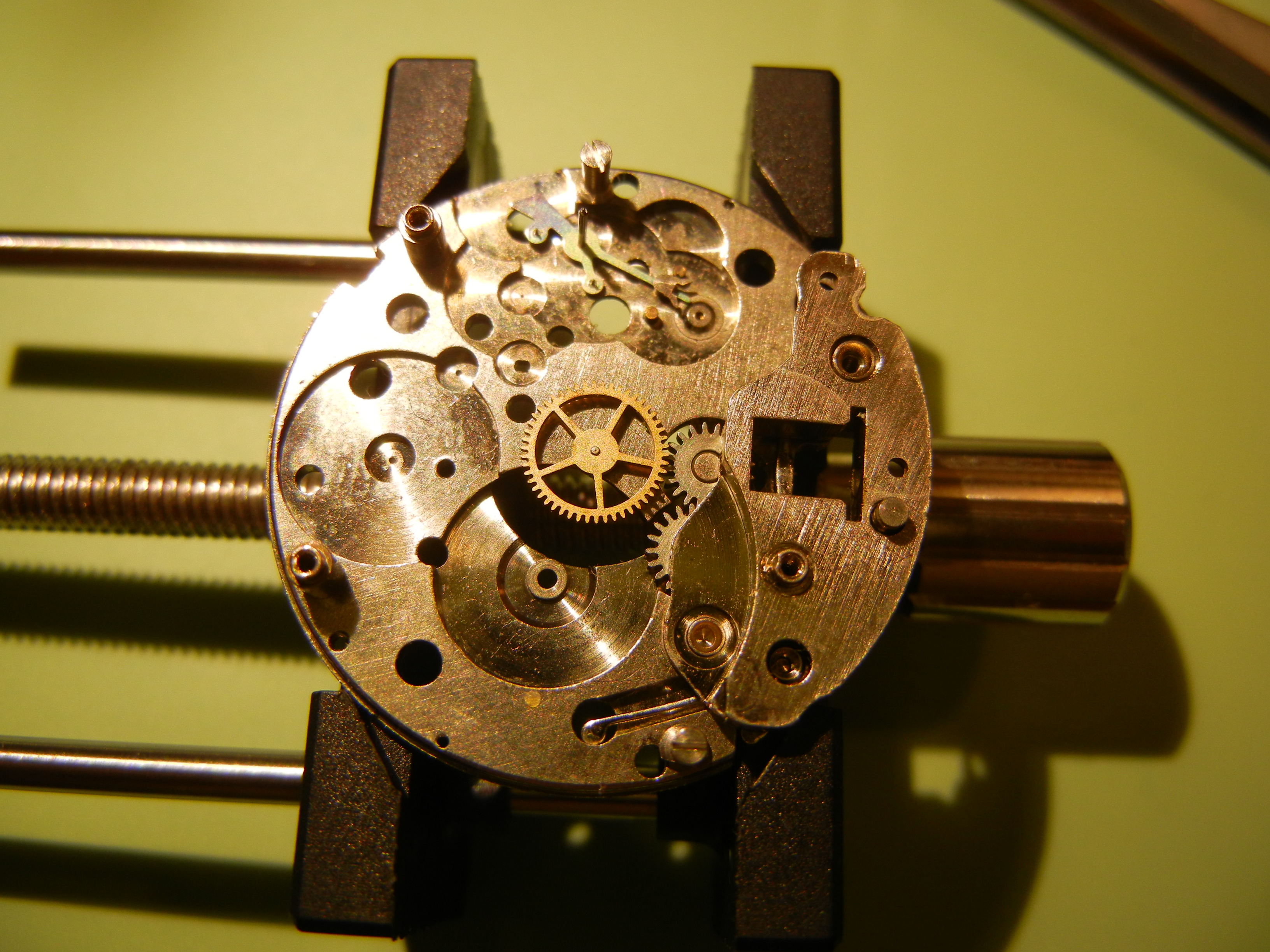
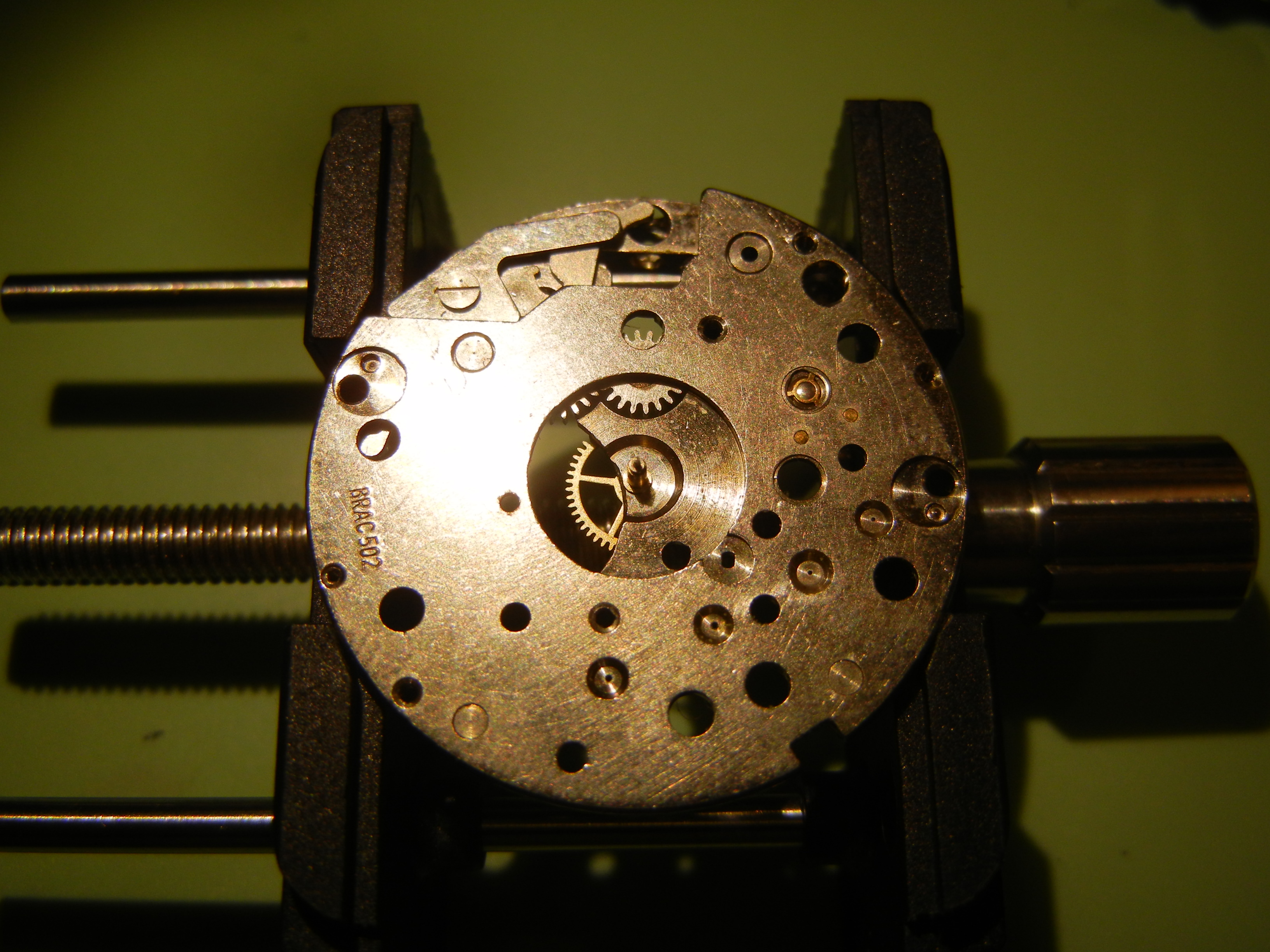
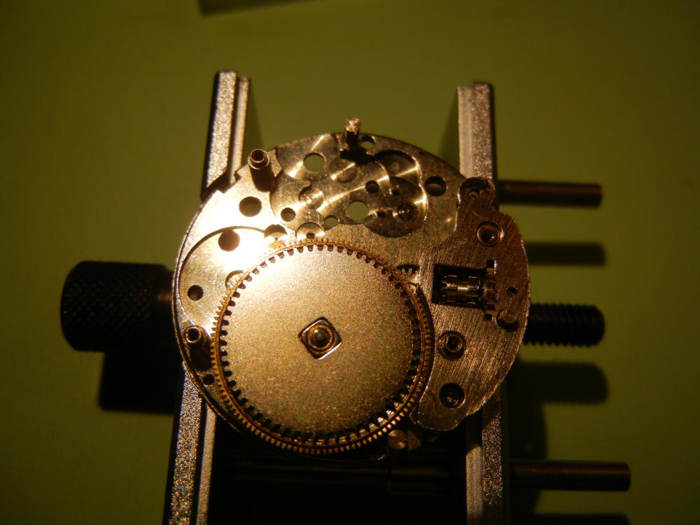
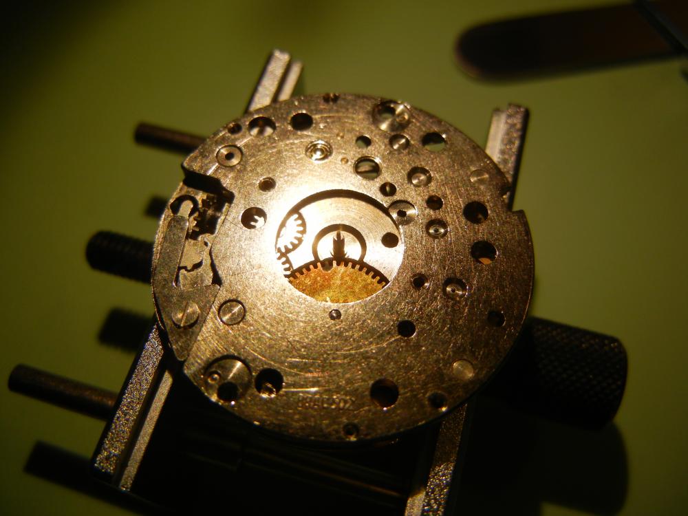
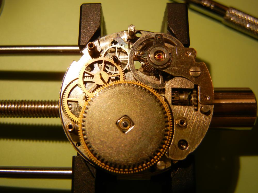
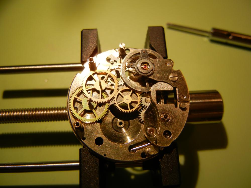
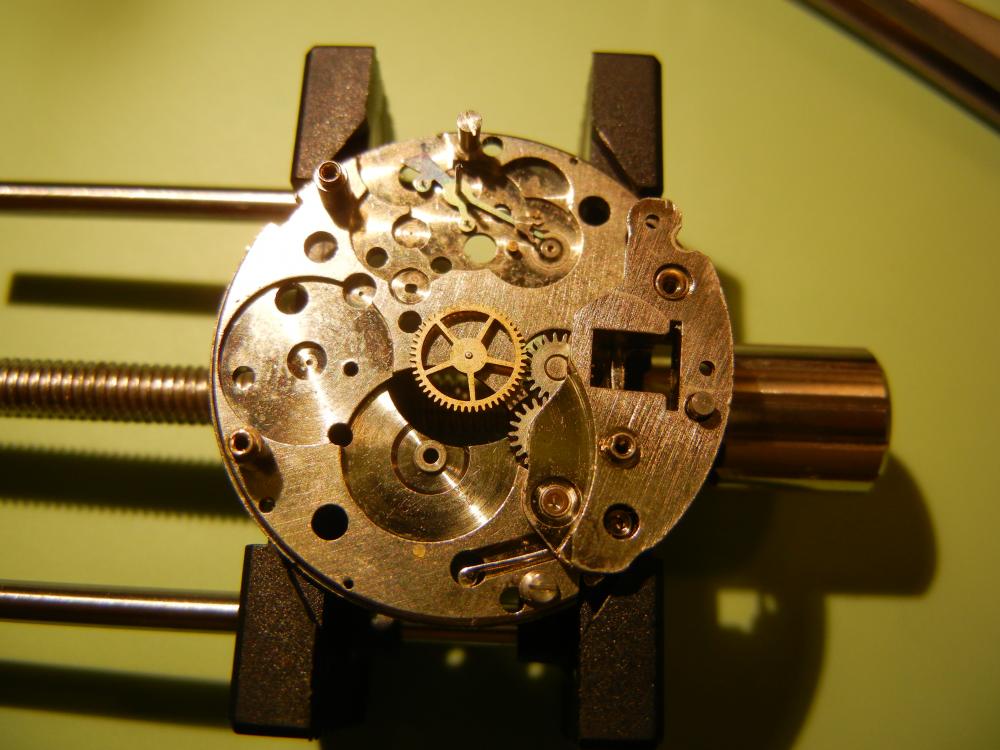
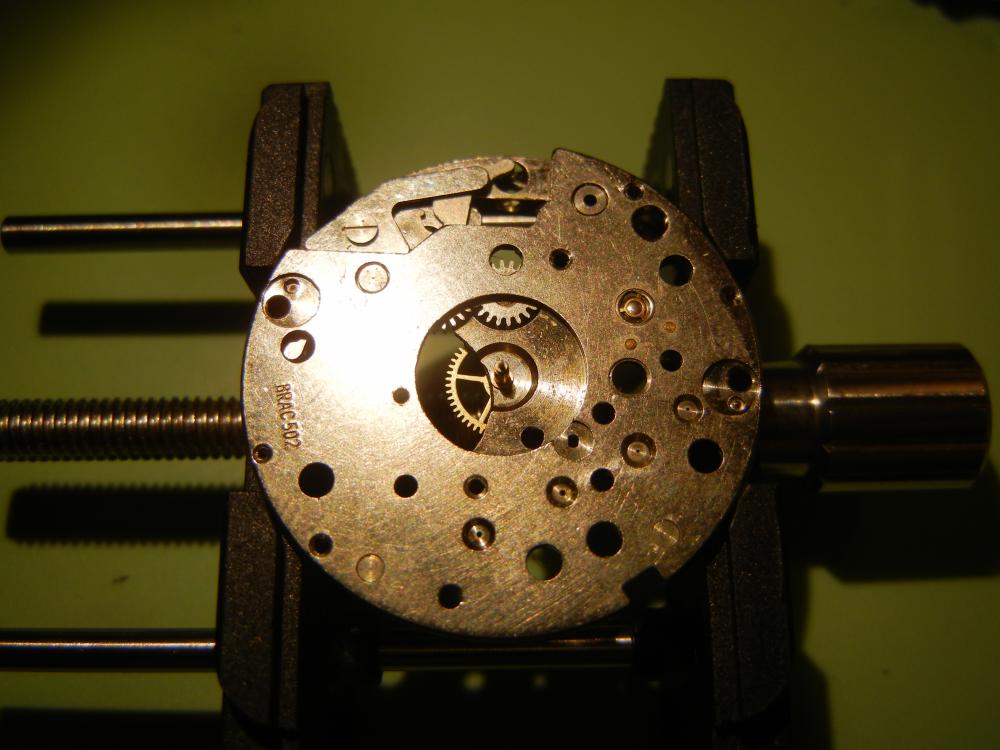
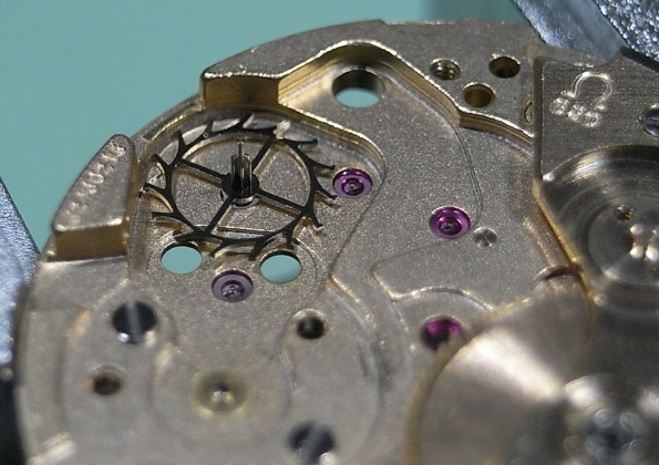
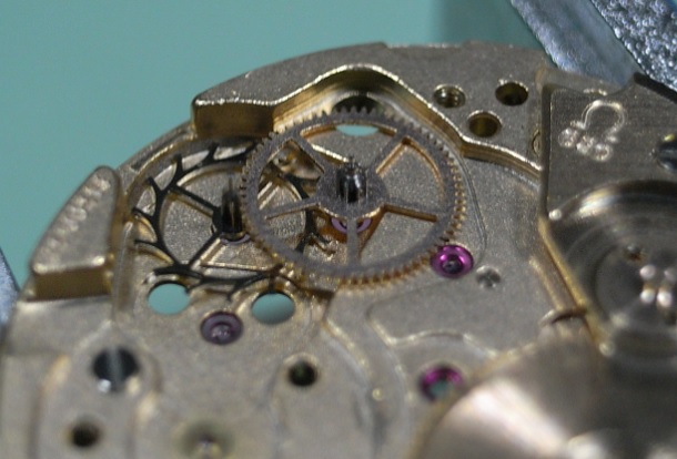
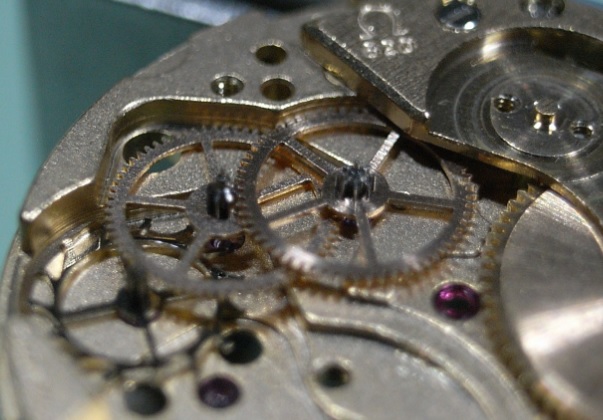
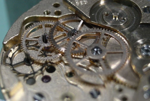
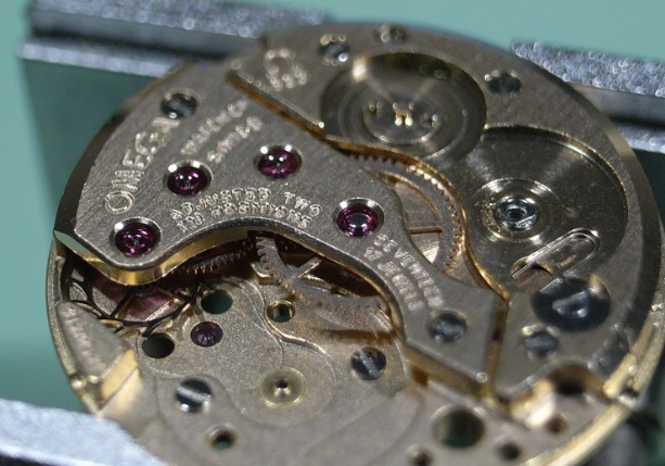
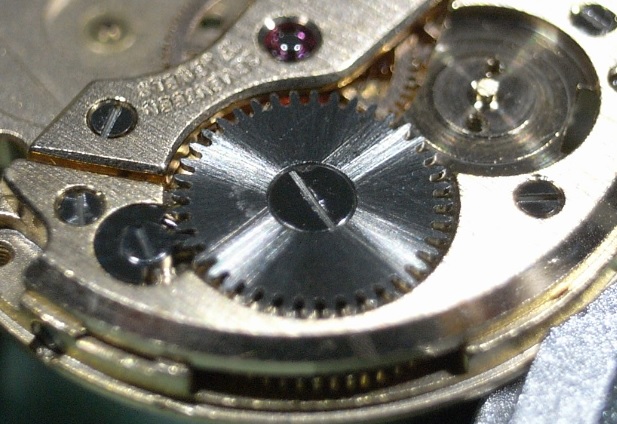
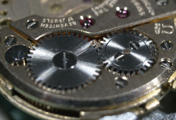
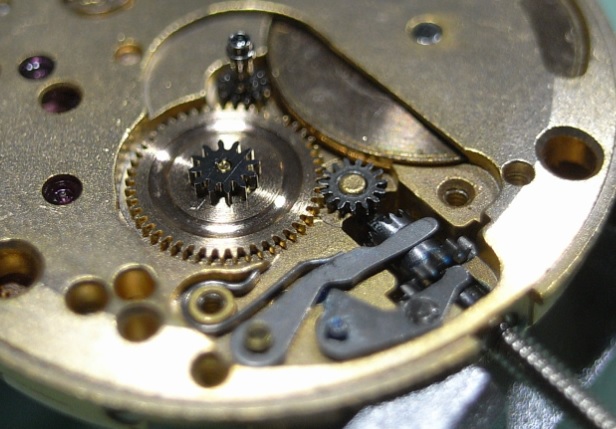
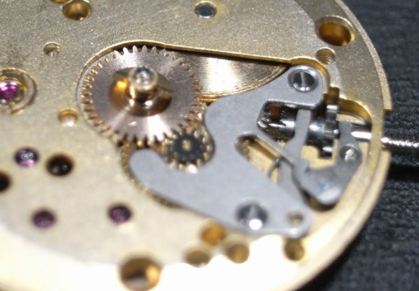
Hello Den, I found some pictures of the BRAC 502, but unfortunately they are incomplete and do not show assembly of the keyless works or the the dial side workings. It does however, show the geartrain:

 1 point
 -
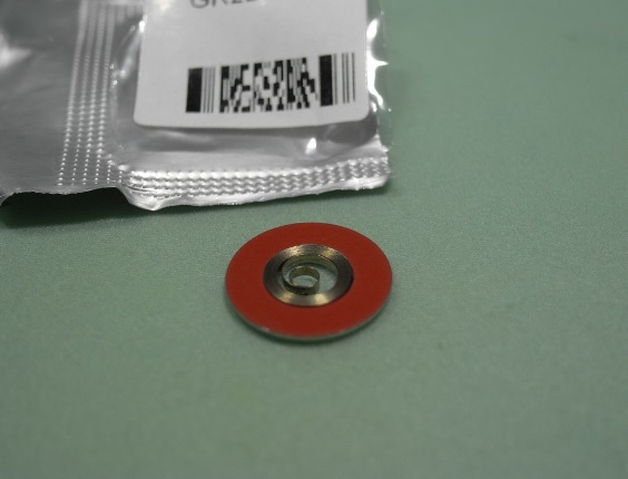
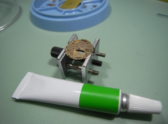
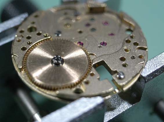
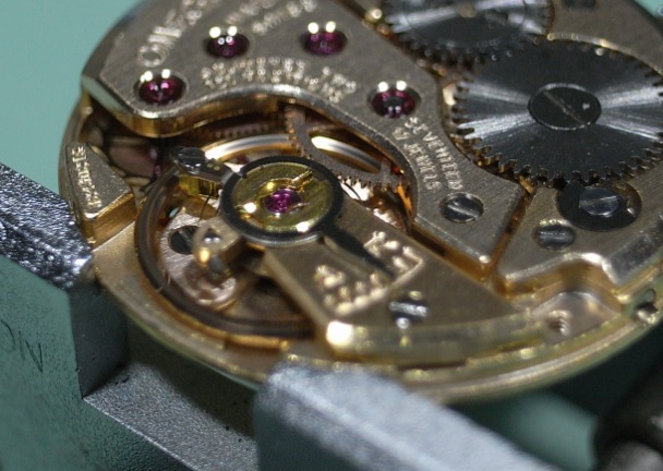
The replacement mainspring arrived at last, so it's time to assemble the movement. To install the new Mainspring, keep the coloured side of the keeper up and press gently into the Barrel with Brass Tweezers. Then install the Arbor . Then replace the Barrel Cover. After discussing this movement with a master watchmaker and good friend, he recommended using Jizma Green to lubricate the Arbor. Install the Barrel and Setting Lever Screw. Then replace the Mainspring Bridge. Install the Click Spring. Then the Click. Now install the Escape Wheel. Next install the Fourth Wheel. Then the Third Wheel. Lastly the Center Wheel. Carefully place the Train Bridge over the wheels, align the pivots and secure. Be sure to always test the free running of the train before completely tightening down the bridge. Now install the Ratchet Wheel. And then the Crown Wheel and Crown Wheel Core. Flip over the movement and place the Clutch Wheel and Winding Pinion. Insert the Stem and then install the Setting Lever. Replace the Yoke and Yoke Spring. Press the Canon Pinion in place. Now install the Minute Wheel and Setting Wheel. Then replace the Setting Lever Spring and Hour Wheel and check it's function, then remove the Hour Wheel to avoid it falling out as the movement is flipped. Flip the movement over and install the Pallet and Pallet Cock. Give the Crown a few winds and test the Pallet's action is free. Then install the Balance, remove the incablocs, lubricate and re-install. Turn the movement over again and after replacing the Hour Wheel secure the Dial. Fit the Hands. Place the movement in the Caseback. Then snap the Top Case in place, and fully test the watch's functions. Check and calibrate the movement on a Timegrapher, and the service is complete. This has been an extremely satisfying movement to service, and I'm sure it will give it's owner many years of pleasure to wear I also trust it helps others and gives them the confidence to tackle the service of this movement.
 1 point
 -
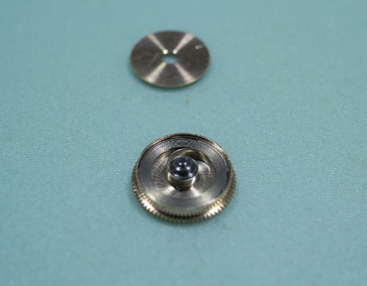
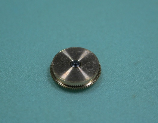
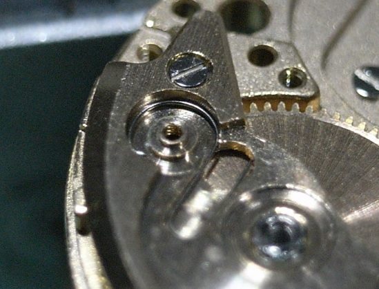
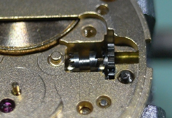
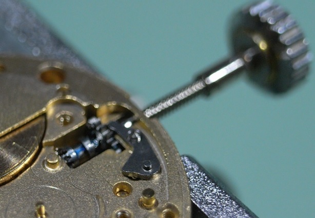
No, it's a bi-directional system, refer to following picture. There's no confusion, we were all saying the same thing.1 point
-
consider a crank shaft, con rod, and piston in an engine. If you align the axis of the crank, the gudgeon pin, and the crank pin all on the same line, then a (for the sake of arguement) 5 degree rotation of the crank either way may result in (say) a 10mm linear displacement of the piston. Now rotate the same crank 90 degrees such that a line from the gudgeon pin to the crank axis is at right angles to a line from the crank axis to the crank pin. Now that same 5 degrees of crank rotation results in (say) 25mm of linear displacement of the piston. This is the same for Seiko's magic lever. The end of the lever attached to the rotor is connected to a pivot that it slightly displaced from the axis of rotation of the rotor, just like the crank pin on a crank shaft. The rotation of the rotor causes a linear oscillation of the magic lever so that the pawls of the magic lever alternately pull on the teeth of the first reduction wheel. I think that most people would agree that the (normal everyday) activity that most efficiently winds an auto is going for a walk, as the arms naturally and effortlessly swing to and fro as we walk, resulting in a similar movement of the rotor. The arm naturally hangs down as we walk so the watch tends to be in crown down (on the left wrist) or crown up (on the right wrist). It therefore make sense for the rotor to be aligned such that the magic lever pivot to rotor axis line is at right angles to the magic lever pivot to first reduction wheel pivot line when the watch is either crown up or crown down, as this results in the greatest linear displacement of the magic level pawls as the rotor swings through an arc, and therefore the most efficient winding. If you get you crank timing out by 90 degrees in an engine you will have major problemsat least in the Seiko nothing gets damaged, however, winding efficiency will suffer. This is not an issue for those who use a watch winder that performs full rotations of the watch, but Seiko's target market, at least for those movements that use the magic lever autowinder arrangement, is the average man in the street who has never even heard of a machine that winds your watch up for you.1 point
-
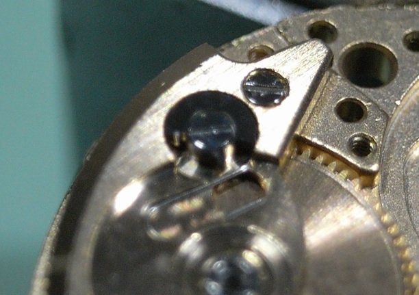
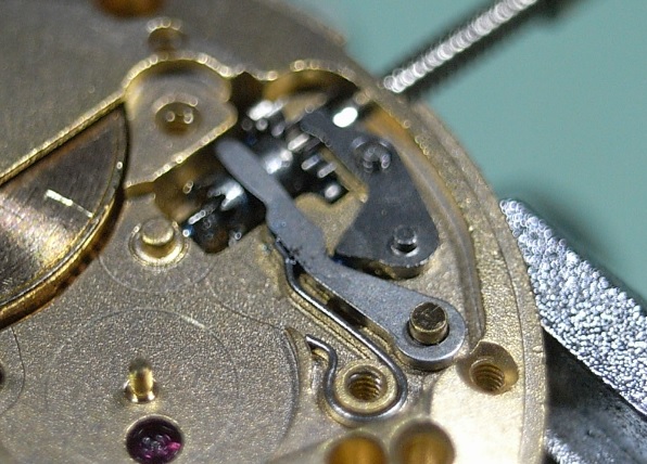
When you optimize the rotor movement, you optimize the magic lever efficiency, because the two parts are linked together. The Magic Lever auto winding is most effective (at preserving power reserve) when the markings are aligned with the weight down (@ 3H), because that is where the shape of the eccentric makes so that the smaller oscillation (e.g. walking) of the arm causes the immediate grabbing of the pawls to the winding wheel. You can check that easily by looking at the pawl action when the marks are aligned, compared to when are not. That is why the rotor has to be installed like in the picture above. Here's an article that explains the matter in more detail https://adventuresinamateurwatchfettling.wordpress.com/2012/09/24/an-intermission-notes-on-the-7s26-autowinder-efficiency/1 point
-
Hi Don, this may help if the construction is similar to K&D. First give the unit a good soaking with this PlusGas http://www.ebay.co.uk/itm/1-X-Plus-Gas-Tin-Spout-250ml-Bolt-Screw-Assembly-Lubricant-Clean-Protect-/391096277473?hash=item5b0f2799e1or equivalent. This is the best penetrating fluid I have come across. He is a drawing of a K&D unit which I "THINK" is similar to yours. If you look at the right hand cross sectional drawing, remove the screw "23" first. Now the remove the locking wheel at the rear "21". Once you have removed these parts, Use a brass or aluminium drift to knock out the assembly "Fig5" shown at the lower left. This will also remove the circular die plate at the same time. Give them all a good clean then lightly lubricate and reassemble. I hope this works for you.
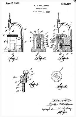 1 point