Leaderboard


Popular Content
Showing content with the highest reputation on 04/05/24 in all areas
-
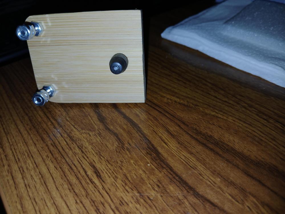
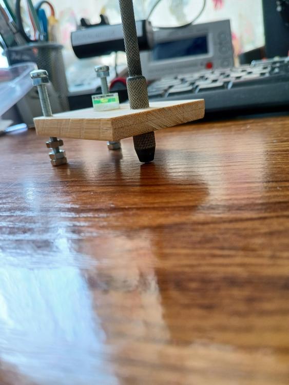
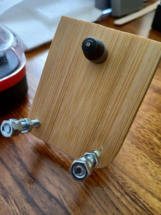
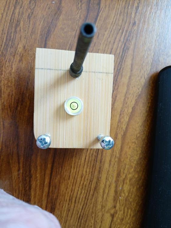
As you can see. Poor photographs, sorry. Works perfectly.
 3 points
 -
The thing with indicator based "mics" is they won't reliably split hundredths as well as a screw mic simply due to their design (though good quality ones can repeat quite well). Also, on many mics, both handheld, table, or the JKA style, the faces of the spindle and anvil aren't particularly parallel. So, if you take a plug gage, and check in several places around the faces, you end up with different readings. This is actually the cheat to wring a good reading from one- check with a good plug gage approximately the diameter you will be measuring, at a given spot, and then check your part the same way. I don't have a JKA but a colleague has one that appears to be a very recent model in new looking condition. Checking with a carbide CARY 0.51mm plug gage, depending on where I checked on the faces it ranged from spot-on, to a few microns under, to almost a whole 0.01mm over. My screw mic of similar design was much closer, spot-on overall, with it reading a few microns under at the very edges of the upper part of the faces. It's a rather involved process to lap these faces correctly; it's really easy to end up with convex faces, so not recommended if you aren't used to it. I'd say it's tricky to have a hard rule on pivot to jewel clearance. In small sizes, 10% would work. That would mean a 0.10 pivot in a 0.11 jewel. But for a center wheel with a 0.80 pivot 0.08mm would be way too much. 0.02 would be fine. So the clearances become larger as the size gets smaller- this is one reason why movements tend to perform less well as the size goes down.3 points
-
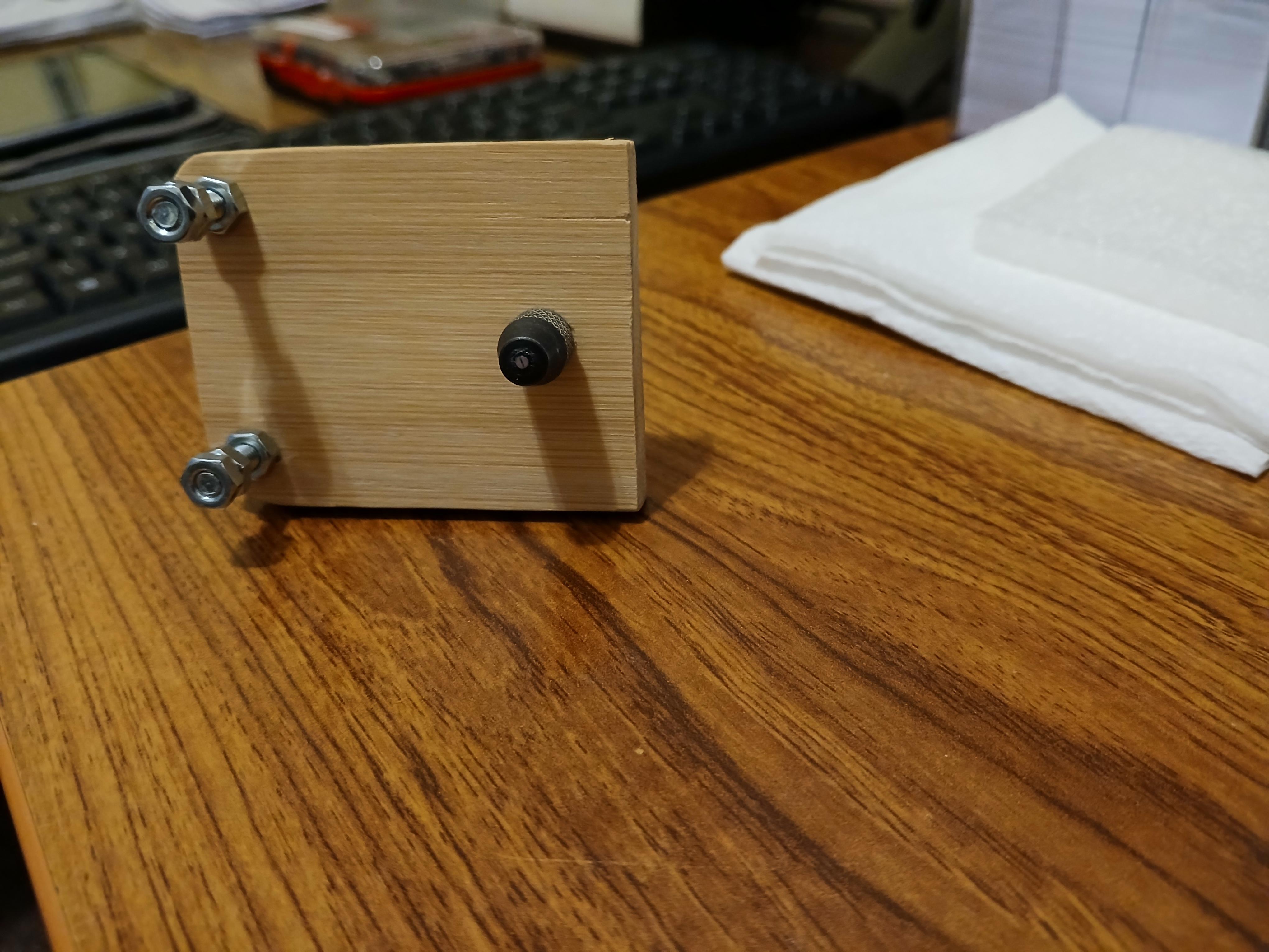
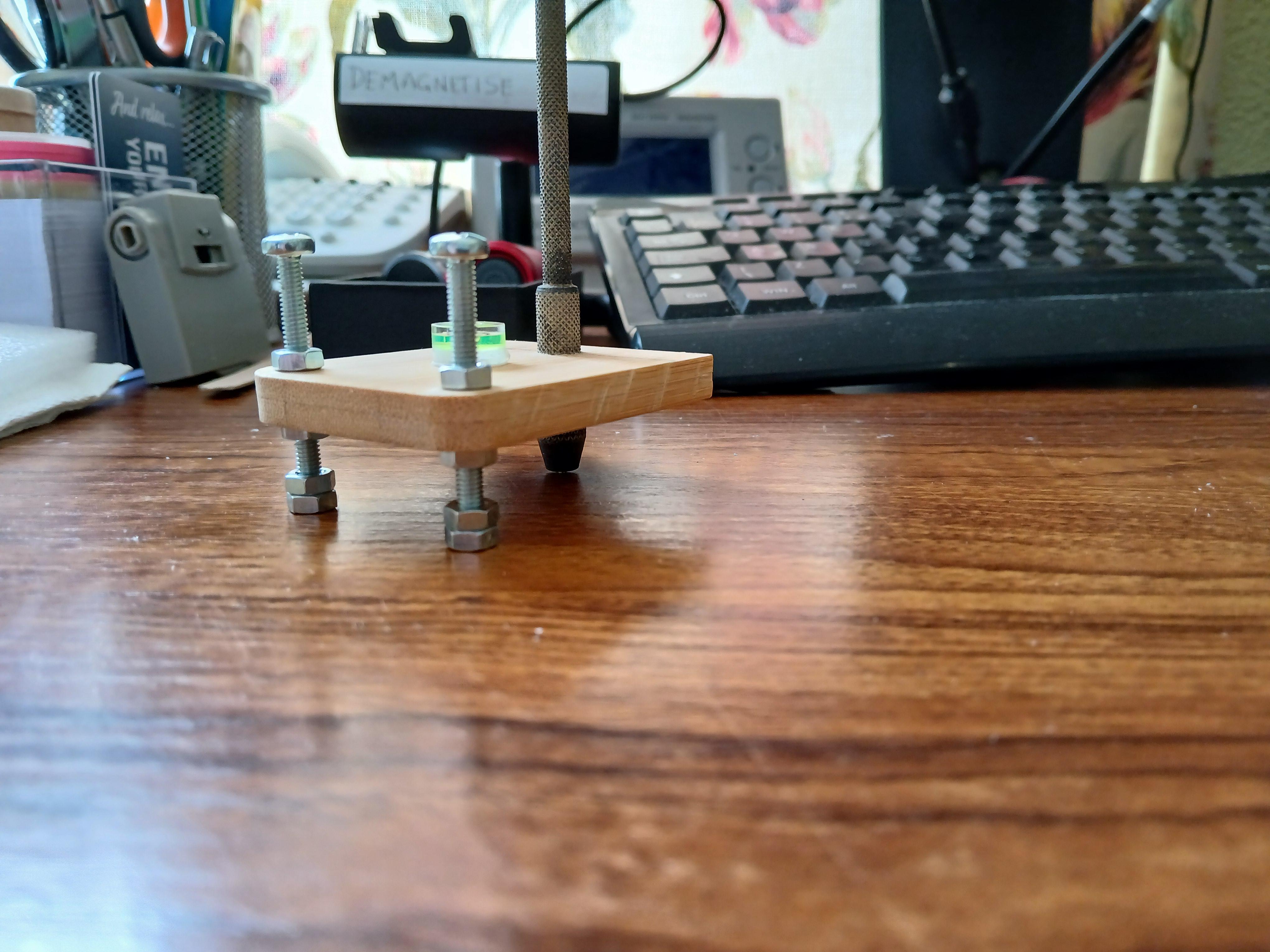
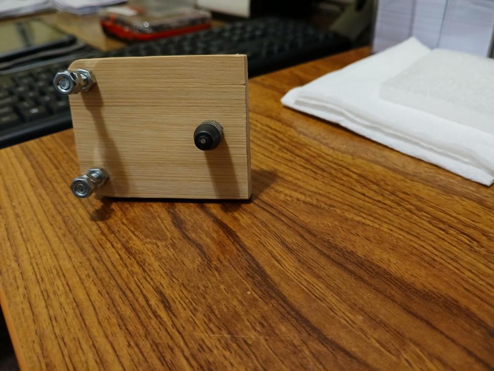
DIY Screw polisher. Inspired by Alex Hamilton, I have made my own screw head polisher. Less than £4 in parts. I hour to make. Chuffed. Additional photograph information Bottom nuts are tightened to make a solid base. Nuts below and above wood are to make the level set when using the polishing base. I will get a small picture frame with glass to insert the polishing paper. The screws can be altered to accommodate. I can now polish to 1 micron. I piece of wood 2" x 2 1/4". 2 x M4-30mm bolts. 6 nuts. 1 pin vice from set of 4.
 2 points
 -
Why not put the clock in another place. You see this old bugger can be helpful at times.2 points
-
Third option and in my view the correct way, level the bookcase.2 points
-
Well done, there is more to changing a movement than a beginner might think. Careful placing of hands, synchronisation of the date change over with the correct time of day, did you remember that first time . Fitting the dial to the movement, precise fitting of the movement ring, releasing and installing the stem. All daunting tasks to a first timer so well done, onto to the next one2 points
-
These type do need to be recessed into the dial though requiring the appropriate milling tool and cutter. Soldered dial feet a few times with low melt bismuth solder, no dial damage. I use 1 1/2" .8mm copper wire. Flame is kept away from the dial by heating the top of the copper wire keeping a close eye on the heat travelling downwards to melt the solder.1 point
-
Excellent feedback. Going to give it some thought. Wife likes the clock in the secretaire so not going there. I did take it down and shorten the pendulum recently and it took over a week of tweaking to get it to run again. At this point I am considering letting well enough alone. Will return and appreciate the suggestions. Again.1 point
-
How about a small plinth of dark stained wood, just big enough for the clock feet or frame, with either an overall taper or wedges adjusted to level the top and then glued under the edge as needed? Add some self-adhesive felt or baize once it is set up, to avoid scratching the top of the cabinet. It should be virtually invisible on top of the cabinet, from what I can see in the photos. (There are places on ebay that sell eg. Oak offcuts planed to 8mm or 10mm, which are perfect for making small stuff like that).1 point
-
You could try low melting point solder - eg. This is for actually for white metal or lead based alloys, but it works perfectly well with brass etc. I use it with phosphoric acid flux, about 6% strength. You can also buy that ready made - or get a litre of 85% phosphoric acid rust remover and dilute a small amount by around 12:1, for roughly the same price as a few ml of ready made... Be very careful with the concentrate - but once diluted it's quite safe as long as you do not get it in your eyes! https://www.ebay.co.uk/itm/124161346588 Clean the surfaces thoroughly first, then cut a tiny piece of solder from the bar with wire cutters or a knife and, rest that against the side of the joint and add a drop of flux with a cotton bud. Then heat gently from a distance with a small flame (eg. chefs torch), until the solder just flows. You can hold parts in place or adjust them with a wooden toothpick or similar, if needed.1 point
-
If the wire is not broken, just insulate it with a small drop of lacquer or nail polish etc. to prevent tarnish. If it's broken, you would need to unwind the ends that are still connected by a turn each, to give enough wire to re-join; then insulate as above. It's probably easier to get a scrap witch with the same movement in that case, though.1 point
-
Yes it is solid. Polishes the screw head well. I am going to attach a flat head (DIY) stump from my staking set into the pin vice, using a larger hole chuck. As Alex's comment, I can then hold any flat item with shellac so that it can be black polished. Not tried that yet, but should be easily possible.1 point
-
Thanks to your advice Dell I've got the clock running, apparently reliably (time will tell!) and it's back for sale in the Charity Shop (they've put a £40 ticket on it). I'm still in the process of regulating it in situ - initially fast by ~5 mins a day & waiting to see what effect one complete turn of the '+-' wheel has. Looking back over the experience I can see I hadn't appreciated just how delicate these torsion springs are and have been lucky not to break this one although I have manged to kink it at both top & bottom when fitting/removing it from the 'blocks'. On this basis, it seems that one answer to my earlier question about what causes the need for the top block housing to be turned left or right to get it 'in beat' is how 'true' the spring is & the angle at which it emerges from the blocks if not exactly 90 degrees. I also found that I needed to shim one of the movements supporting pillars. I'm very grateful for the interest you & others have shown in my little project. That seems a good idea Nev. Unfortunately I didn't have such a device to hand but will look out for one for future use - time-consuming (not to say frustrating) though working on this 400-day example was, I haven't been put off addressing another one should the occasion arise....1 point
-
Hi Murks. The problem with soldering the dial feet is the possible damage to the dial face due to heat. Having said that if the heat is applied for milliseconds you get away with it no problem. Now comes the sticky bit. You can glue feet on use dial dots, or solder them on. Soldering requires some apparatus to hold the dial and wire whilst applying the heat. I actually built my own machine and it works very well. So the options are purchase the tool or make your own Google dial foot soldering For more information.1 point
-
Ok that makes sense. Thank you so much! I will try not to fling anything across the room. Haha if they made a loupe that could magically fill the gaps in my knowledge I promise I would be the first to order it.1 point
-
Yes , only the gap is cut on the setting, not a chaton.1 point
-
1 point
-
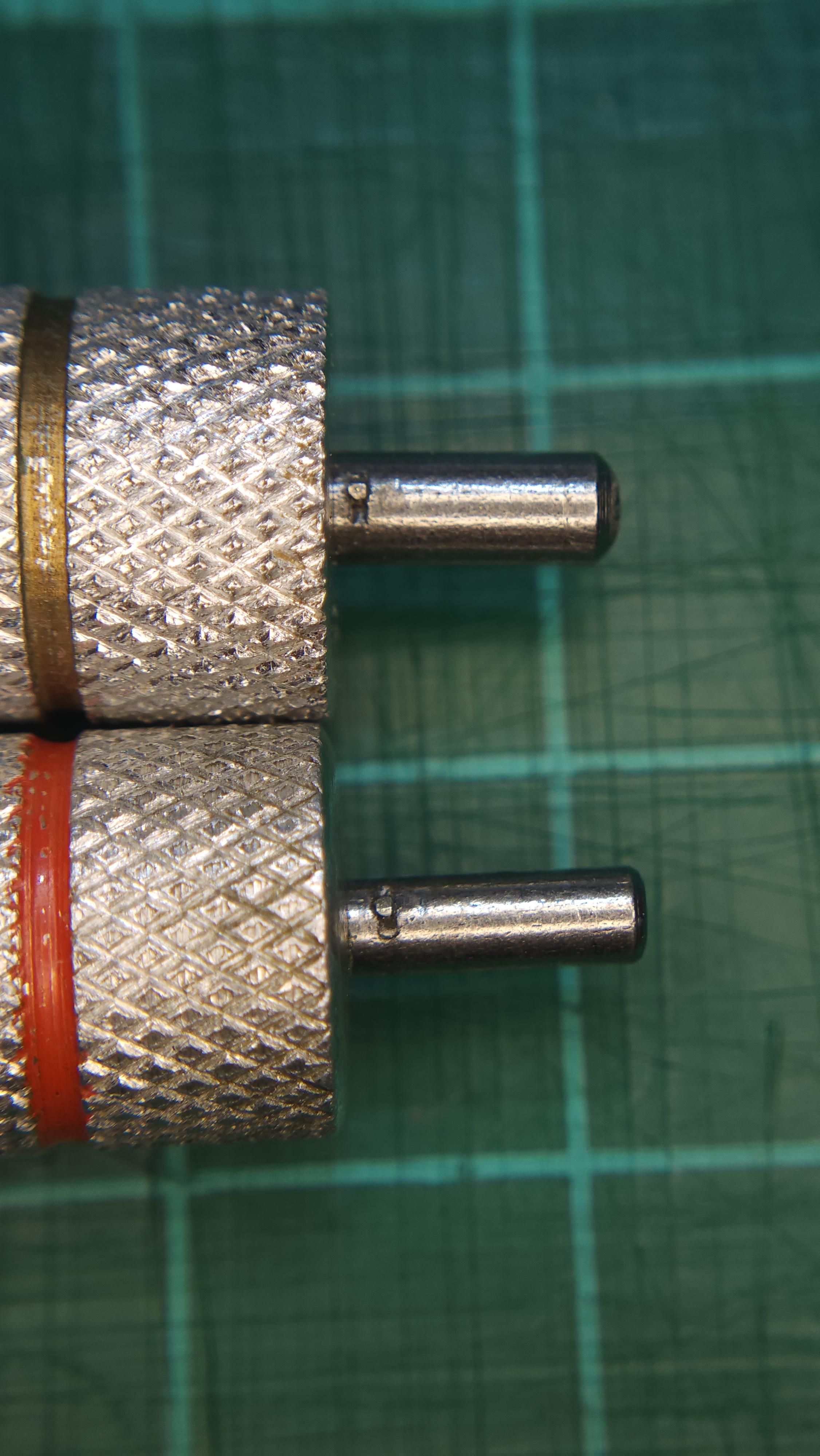
After buying 6 set of different winders and always coming across a mainspring that just doesn't fit any winder I possess, I think I might have solved my problem. I took my K&D winders and ground off any remnants of the arbor hooks. Then I drilled a 0.5mm hole and fitted a plain 0.5mm stainless steel wire with Loctite. This would allow me to wind in both clockwise and anticlockwise directions. Then the problem of the winding hook being too tall for modern narrow mainsprings was solved by pushing down on the arbor and lowering the height of arbor hook. In the above photo, the arbor of the yellow winder has been pushed in, so that it lies in the centre of the width of the mainspring that I intend to wind. If I need the same arbor for a wider mainspring, I can push it out again. So, let's see if it has finally solved my problem.
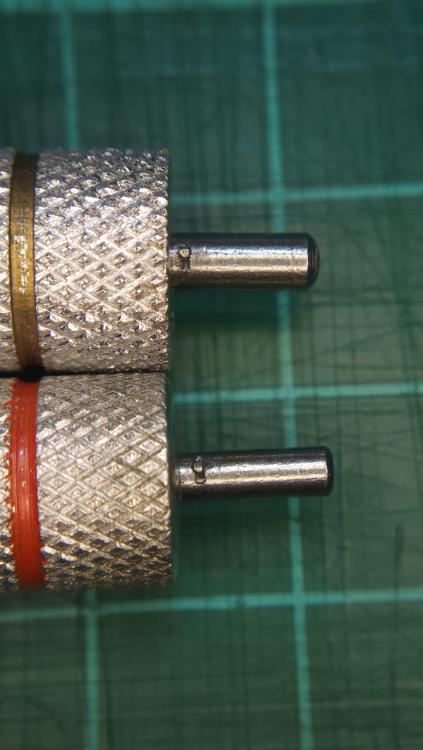 1 point
 -
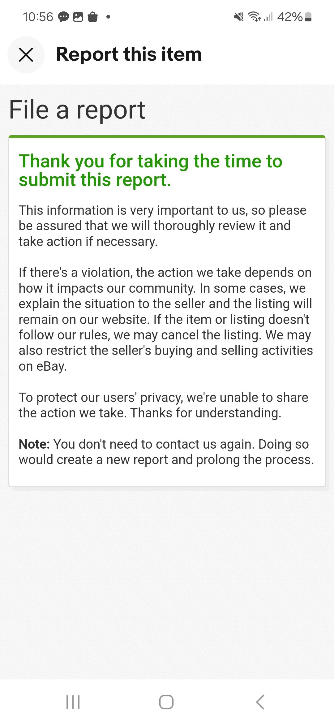
I sometimes visit a forum devoted to watch reproductions and I've seen posts where they say a seller is listing a fake as the genuine article and they seem to be able to report them and get the listing taken down. I think this page is how one can report a seller or listing.1 point
-
1 point
-
Well, first screw would be cosmonaut , but please mike don't tell Ross I said that. Wise idea.1 point
-
Hey nice! That's a lot smaller than the cinderblock taking up my valuable desk space
 1 point
 -
Ok, it gets even weirder. I did a Google Lens image search on one of his photos and found that it was from an earlier eBay listing. And it's from Pakistan. https://www.ebay.com/itm/4044625307891 point
-
Hi Ross a cunning piece of thinking Itb will do exactly what the pukka tools will do at a fraction on the cost well done for thinking outside the Bergeon Box.1 point
-
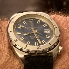
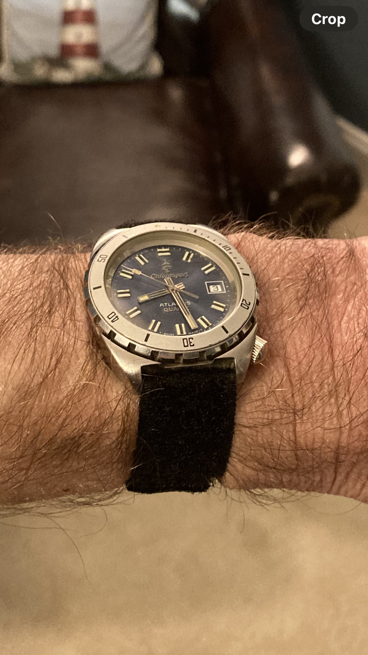
I received the ESA 944.111 movement today from Germany. I successfully reassembled the watch with the new movement and everything is working perfectly. I realize that this is very basic work for those of you who have helped me with your comments but I have to say it was extremely rewarding to bring a 42 year old watch with sentimental value back to life after being broken for 19 years. I also have to say, it was not quite as straightforward as I imagined . As always I learned a lot so that it’ll be easier next time. On to the next project. Thanks to everyone for your help.
 1 point
 -
I saw that one. Is Vevor an Amscope copycat, looks much the same, with the same numbers. Myself, I got an Amscope SM-4T - it’s fantastic.1 point
-
…the first screw would be a beeping toaster that causes panic in the United States, then a dog screw, then the cosmonaut…0 points