Leaderboard


Popular Content
Showing content with the highest reputation on 03/08/17 in Posts
-
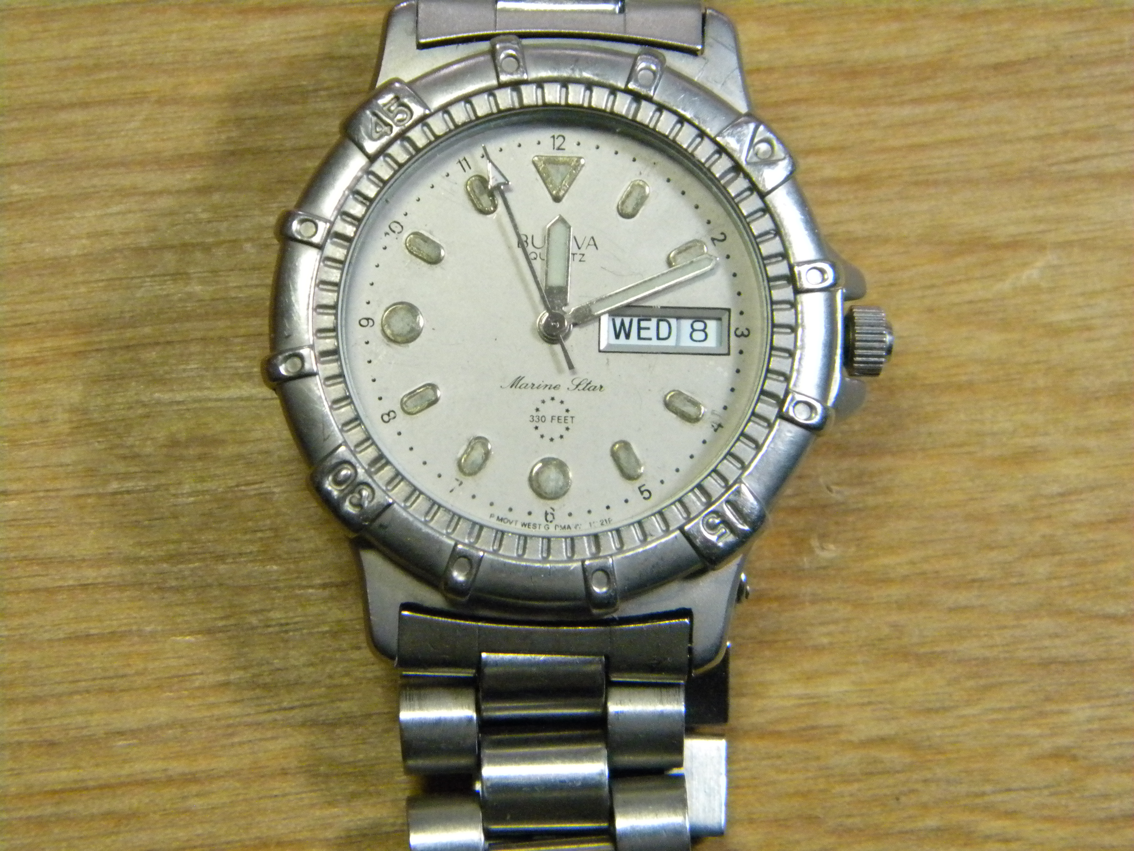
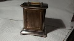
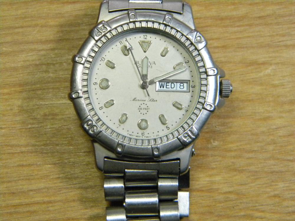
Here is my beat up and twice rebuilt Bolova. I need to clean and overhaul the face and repaint the luminous points on it. This watch is my favorite and started my whole watch repair journey. A "free" battery change had damaged the gasket and filled the watch with water while swimming in 1999. A few years ago I found a book on fixing and building watches and this was my first repair. It now it has a Ronda movement. DSCN0655.JPG
 2 points
 -
Hi tourbillon, no problem: Frank
 2 points
 -
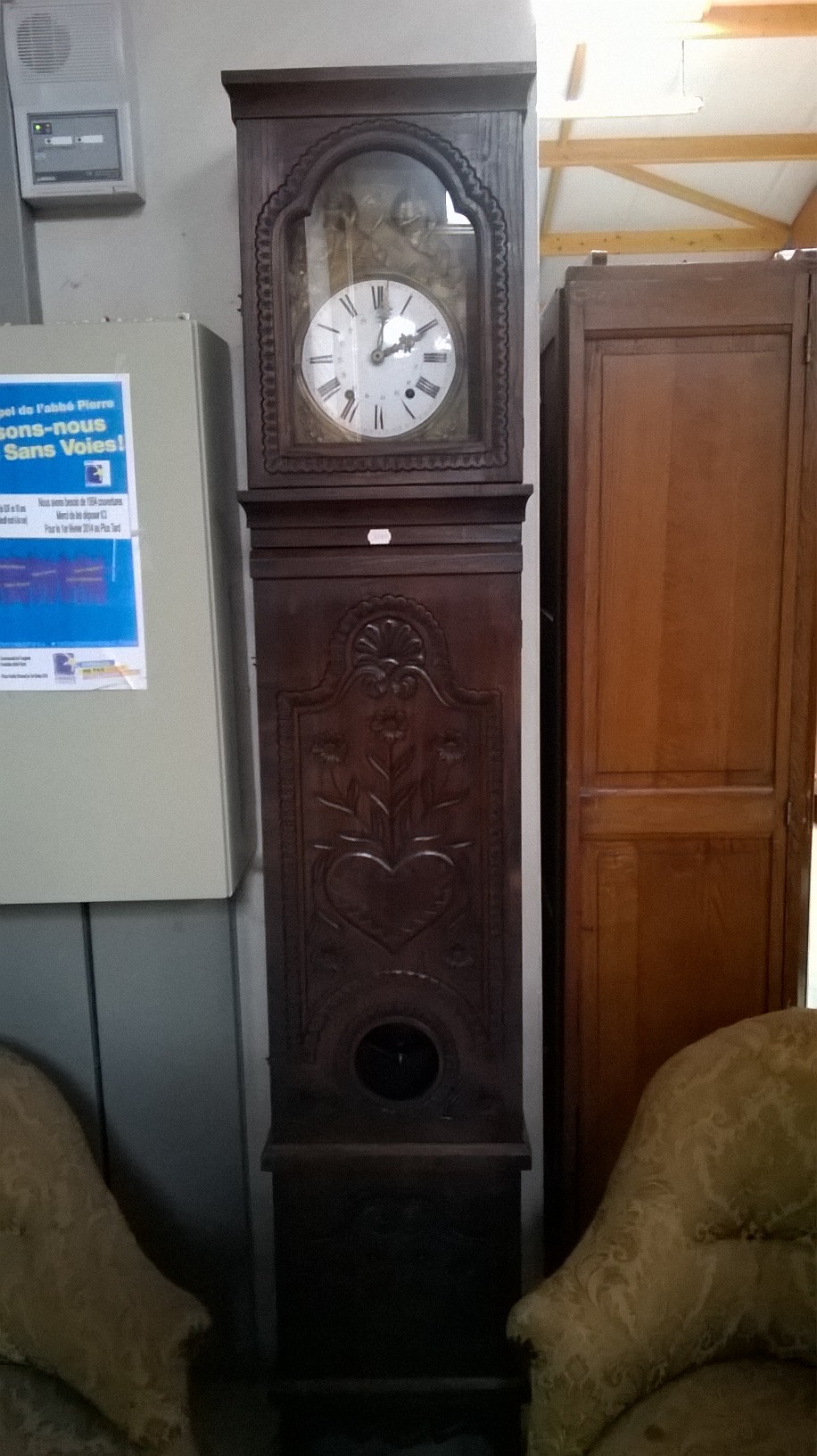
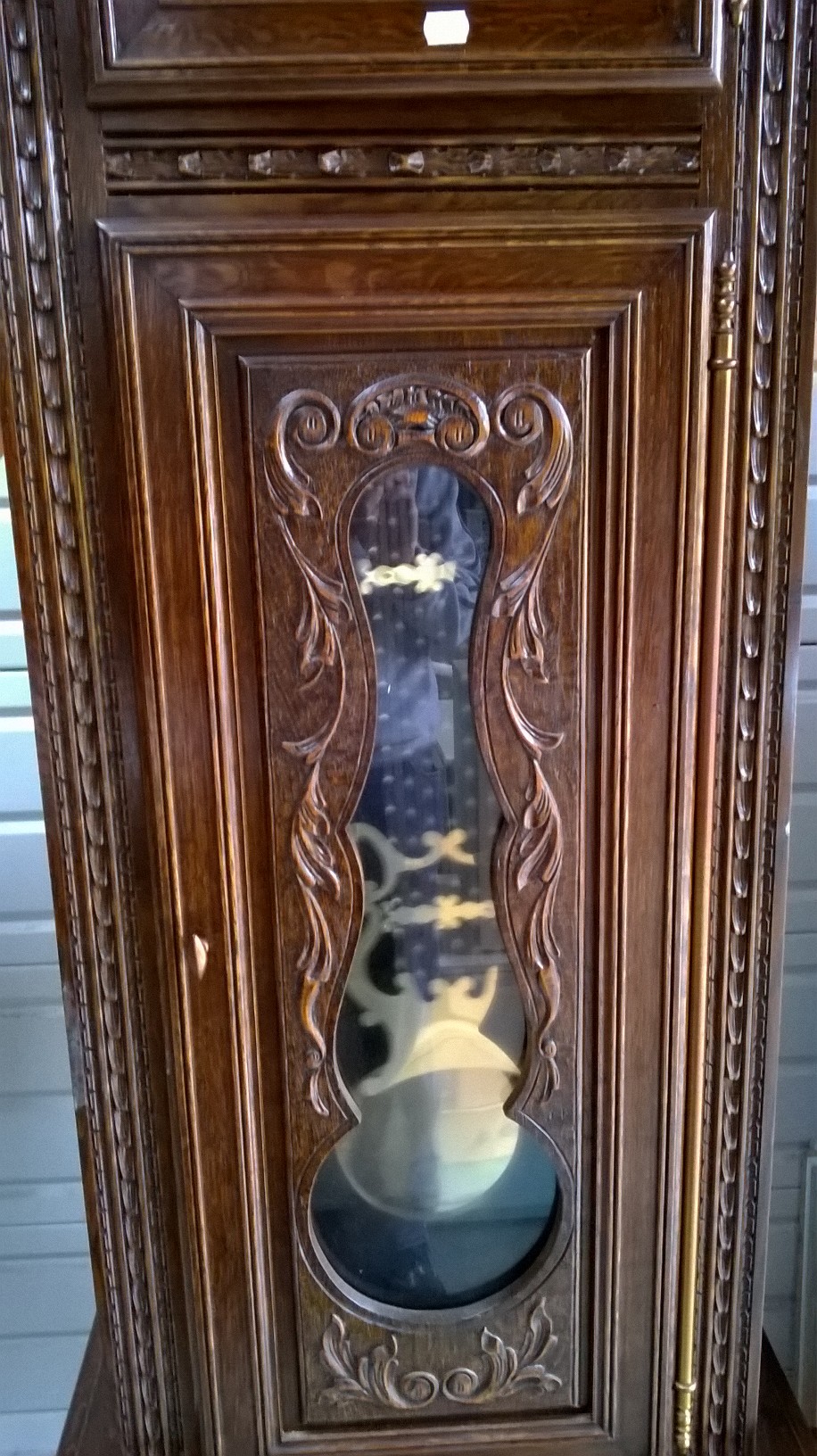
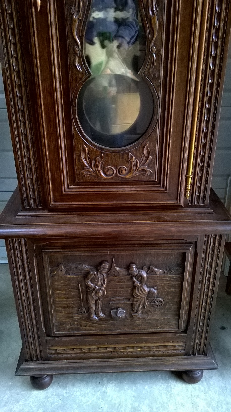
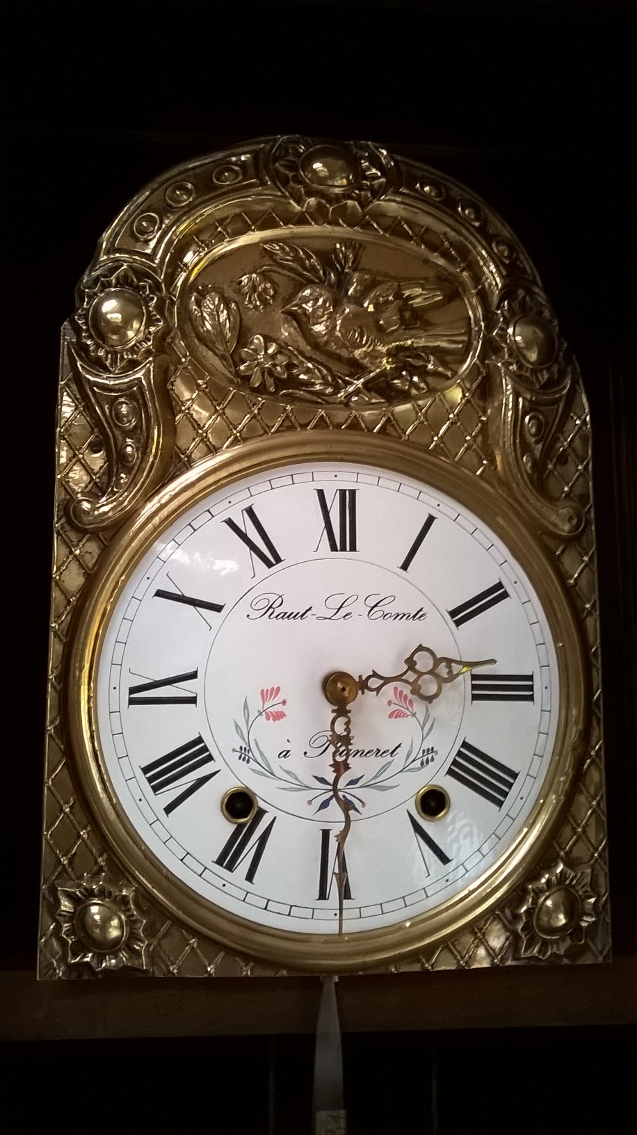
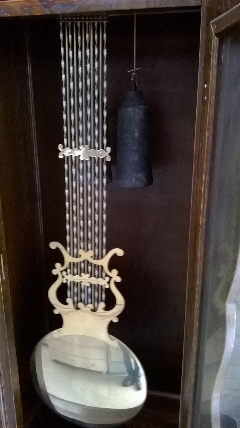
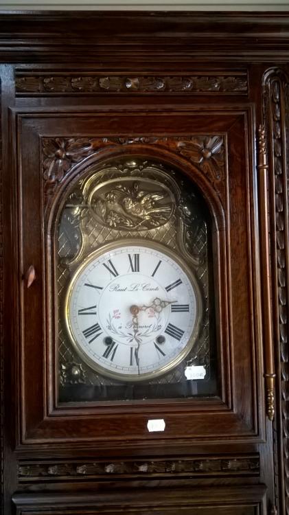
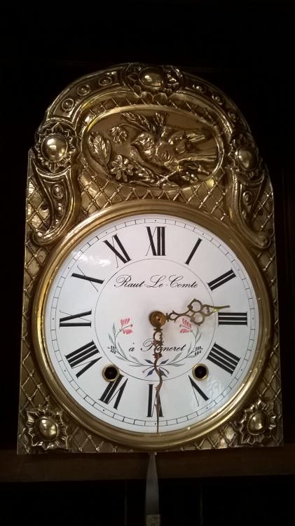
This afternoon I visited my favourite antiques warehouse here in France, there are often clocks at great prices and today was no exception. There were at least half a dozen Vedette wall clocks priced around 5 Euros, and these two longcase clocks. I did manage to resist temptation and kept my hands in pocket .


 1 point
 -
Thanks for the warm welcomes everyone!1 point
-
You are correct Quartz watches are mostly immune, but strong fields can mess with the stepper motor. The point I was trying to make is avoid magnetising any part of watch and purposely magnetising a screwdriver is a stupid idea.1 point
-
praezis, I'm going to have to try the 1 transistor amplifier. This won't work with a Line-In connection of course (because it expects a stronger signal, and has no bias voltage), but my current PC only has a Mic input anyway. (On a related note, I've always found Line-In, when available, to be much less noisy than Mic-In.) tourbillon, thanks for the kind words, and pointing out the typo in the link. I've fixed it on the web site, and it will be fixed in the manual when I release the next version (something I meant to do early January, but never got around to because of other urgent tasks that came up).1 point
-
Without removing the dial & hands it is always difficult to analyse the fault. I have found a link which shows drawings of the 8541. http://www.gregsteer.net/IWC/Cal_85/Calibre8541Watches.htm Also see below a pdf of the parts & ref numbers. I have noticed Cousins carry most of the spares if required but they are on the pricey side. 6686_IWC Cal 854, 8541 .pdf1 point
-
Thanks Shirley, good choice on the Corolla, great cars, used to have a Toyota, one of the most reliable I've ever owned, enjoy.1 point
-
Here's my two cents (which, owing to inflation and all, isn't worth a plugged nickel). Use your naked eye for what you can. If you need more, use one of those jeweler's headband magnifiers. To get in closer, use a 3x, 4x, 10x loupe. To get down to the nitty-gritty (hairsprings, roller jewels, etc) use a 20x loupe or resort to a microscope. The more the power, the closer you have to get to your work and the more distortion you'll have around the edges. My eyeballs are older than Accutrons, so I use a 10x loupe as pretty much a standard practice. No matter what you use, be sure to have some fun with this rewarding hobby!1 point
-
What you have is a cylinder watch movement, there's no pallets with this type of movement. it is a direct drive of power through the train to the cylinder, by means of the teeth which are very different to teeth on escape wheels which use pallets, it is combination of the teeth on the escape wheel and cylinder which allows the power to escape evenly, if there's wear to the cylinder the action of the balance wheel will be poor. Some cylinder movements are poor timekeepers. Here is a link which will explain the escapement better for you. http://www.datacomm.ch/rbu/C4.html1 point
-
Hi I think I actually succeeded in tightening it. At least it turns the the centre wheel now and I'm hoping the watch will set as well. I had to hit it a bit harder than a light tap. I held it with a pair of tweezers and that seemed to work fine. I actually used the sharp point punch and while I held the pinion on a flat stump. Anyway, it's tighter. Dave1 point
-
Magnetism is not desirable on your driver blades or tweezers with particular reference to mechanical movements. It's not such an issue today with modern watches but if you introduced Magnetism to the hairspring this can cause the coils to stick together during oscillations and the watch will run abnormally fast. Carbon steel tweezers are prone to magnetism, far more than stainless steel. Also not all jewels are rubies some can be from other hard stone and can even be transparent. Also magnetism, if significant enough to other parts of the movement could have an adverse effect on the moving parts with regards to friction, ie.. pushing or pulling. Professional Watchmakers constantly de-magnetise their tools. Sent from my SM-T585 using Tapatalk1 point
-
The friction would be on the center wheel upon which the cannon pinion sits. JC1 point
-
I think the gold and silver combination says POW! look at me. Love it!1 point
-
Another great piece of outstanding improvisation szbalogh, I enjoyed watching that!1 point
-
Next phase done https://www.youtube.com/watch?v=j3gxp96WjCI1 point
-
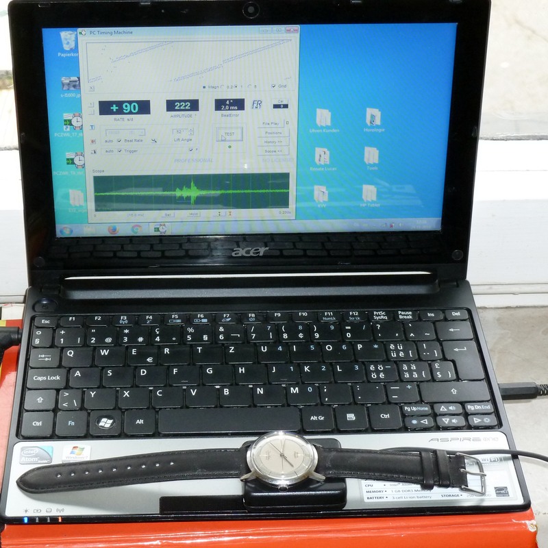
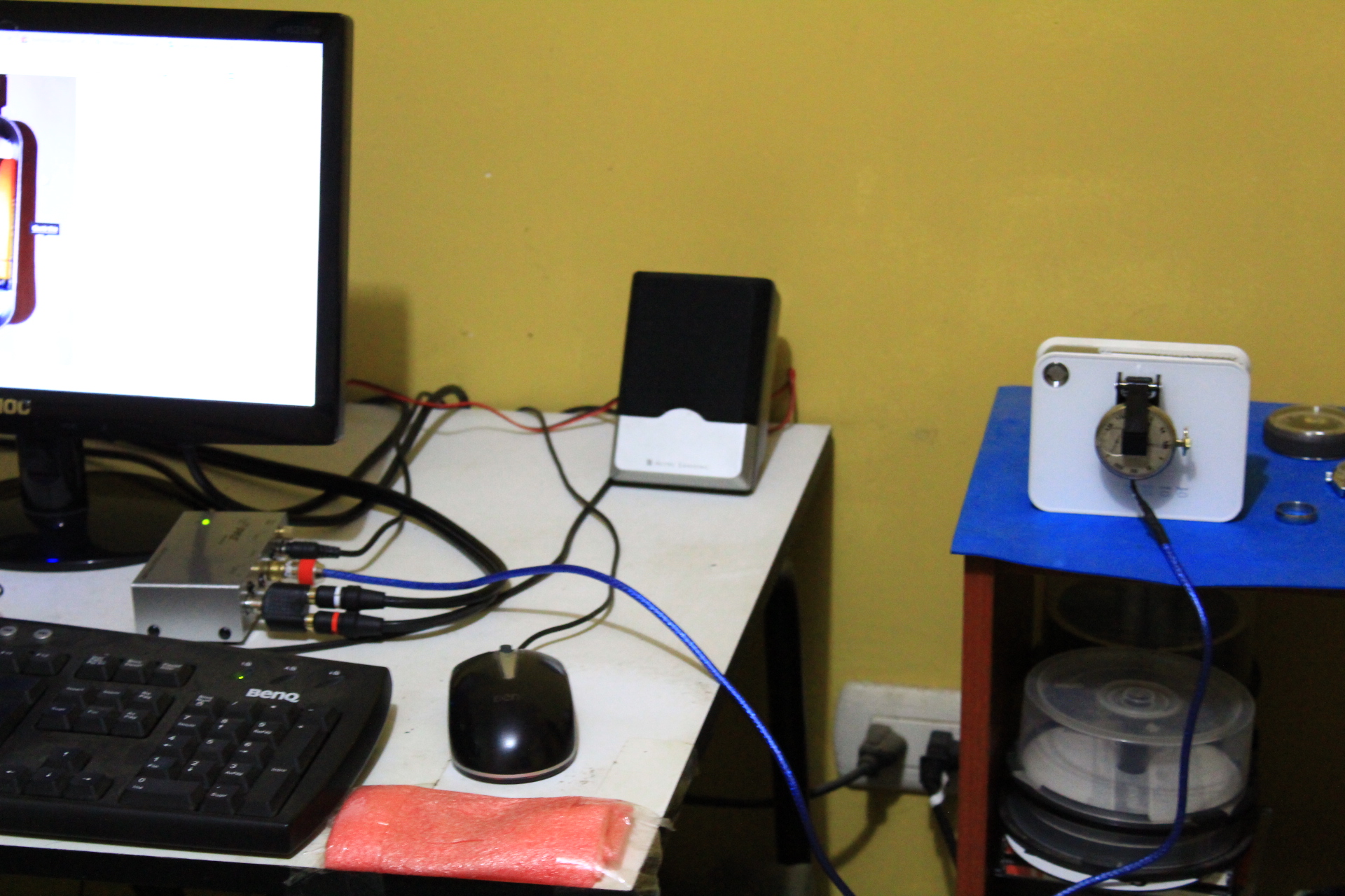
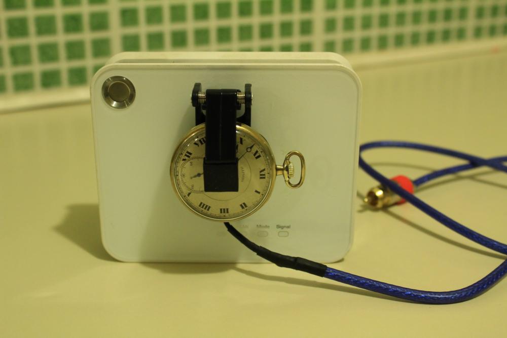
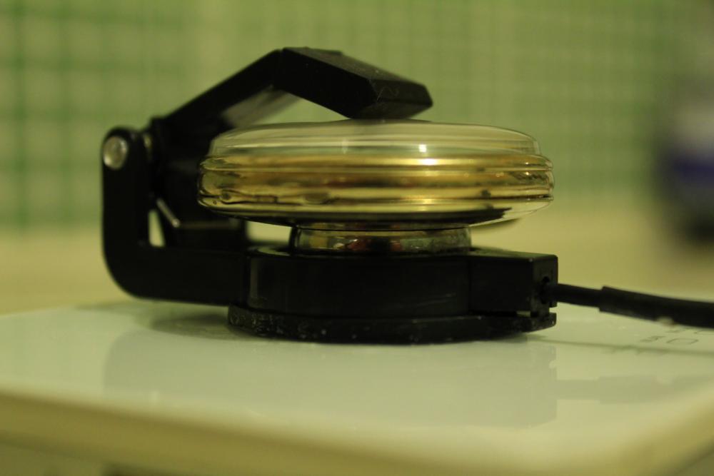
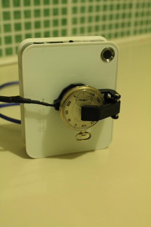
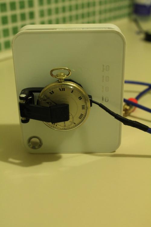
Hi, with interest I followed your discussion. And I am astonished how complicated circuits you designed. As I understand, the program contains a band filter already. So no sophisticated filtering, in fact not any, in the preamp should be needed. Also many stages are overkill imho. My experience showed that 10...30x amplification after the piezo disc is sufficient. This can be done with a 1-transistor stage, and using the voltage and internal resistor that are supplied by the MIC input, no power supply is needed, too. @wlysenko: you inserted one more OP stage to compensate for wide differing piezo capacitance. You can avoid it and reduce the differences (about 4...30nF/disc) to few % by using a low input capacitor, e.g. 2.2nF. You can include it then in your filter calculations. Added a photo of my setup, microphone has the mentioned 1-transistor PA: Regards, Frank
 1 point
 -
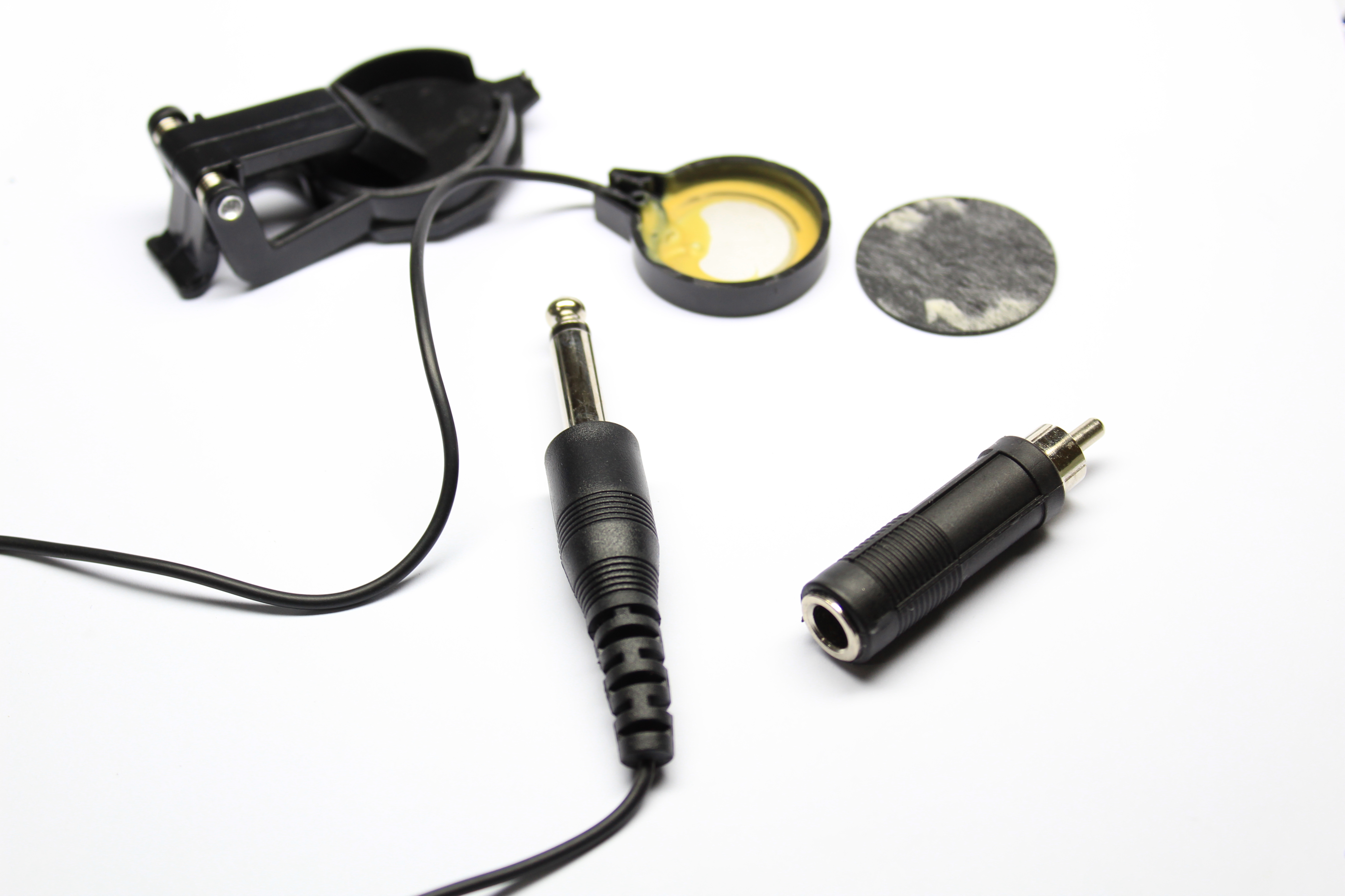
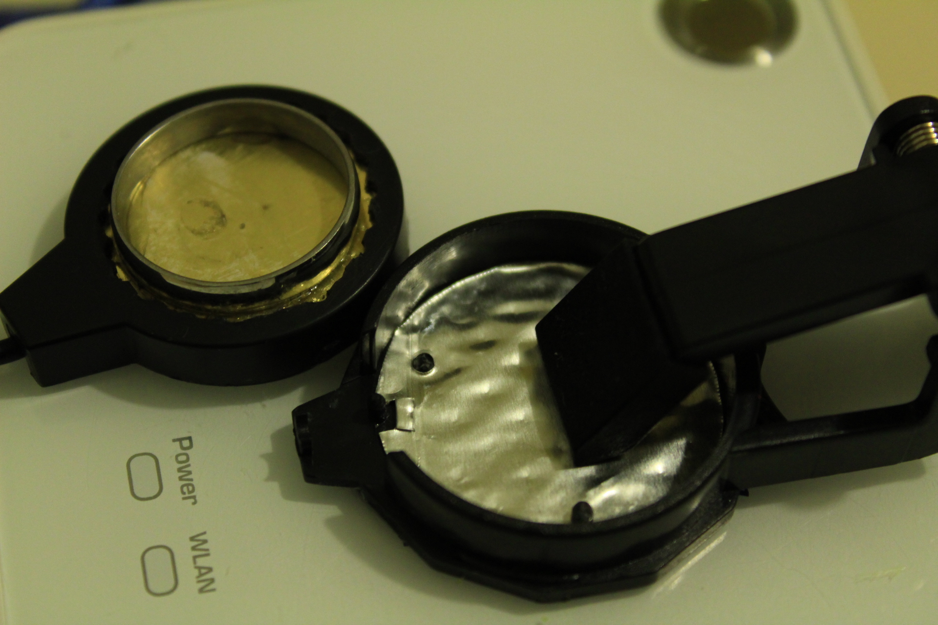
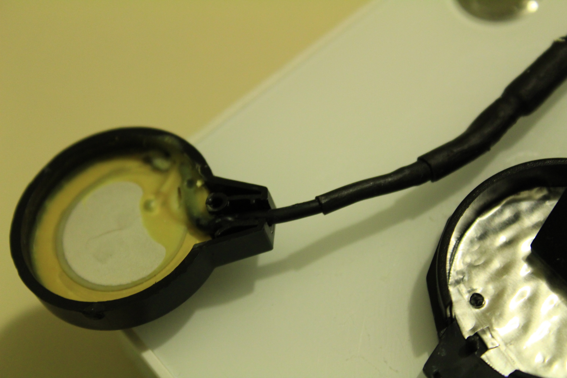
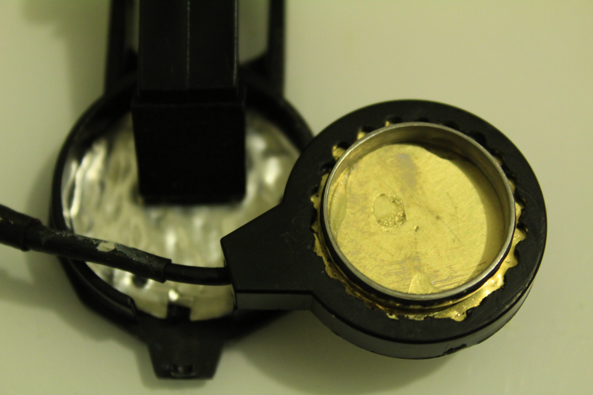
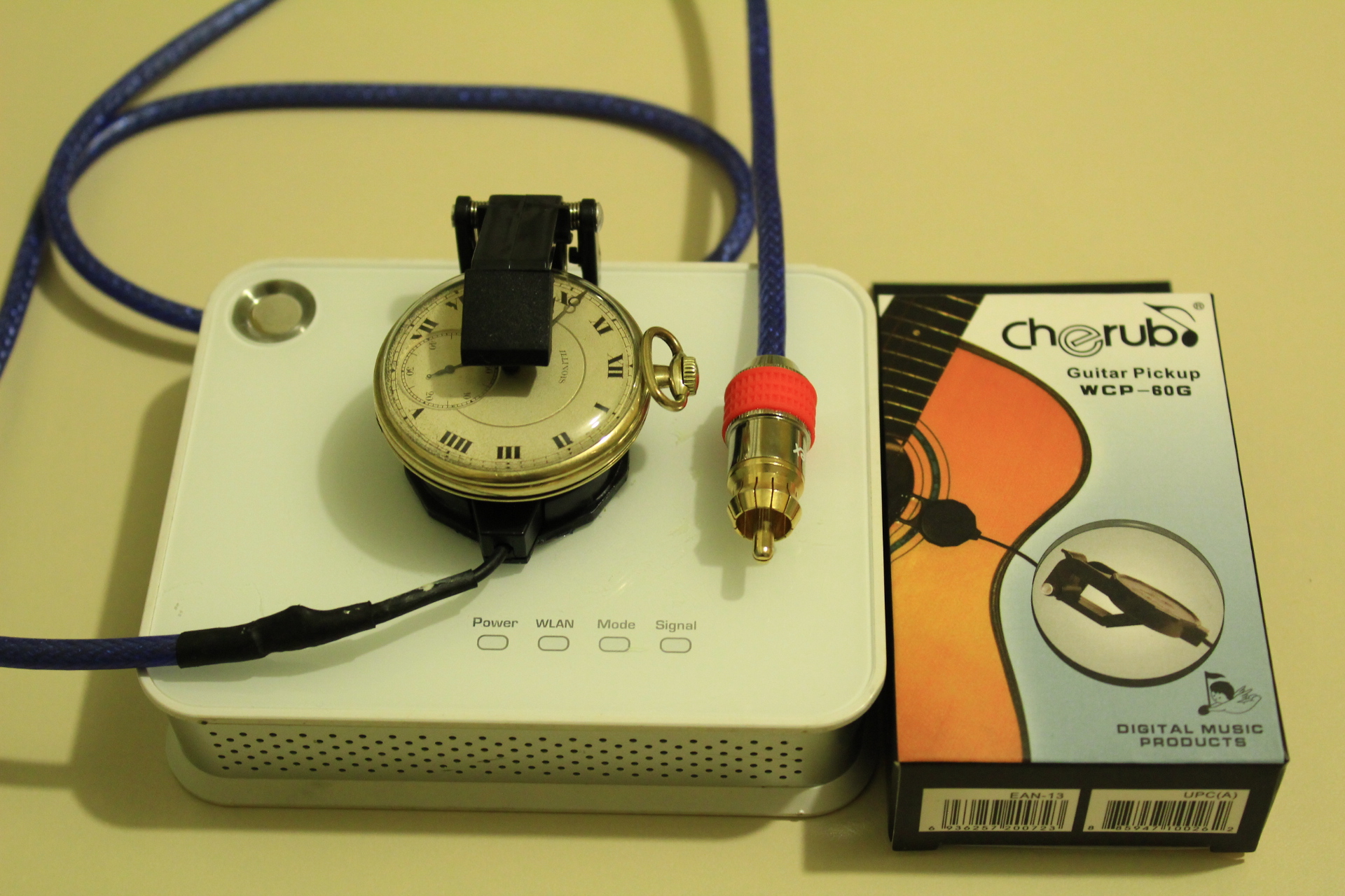
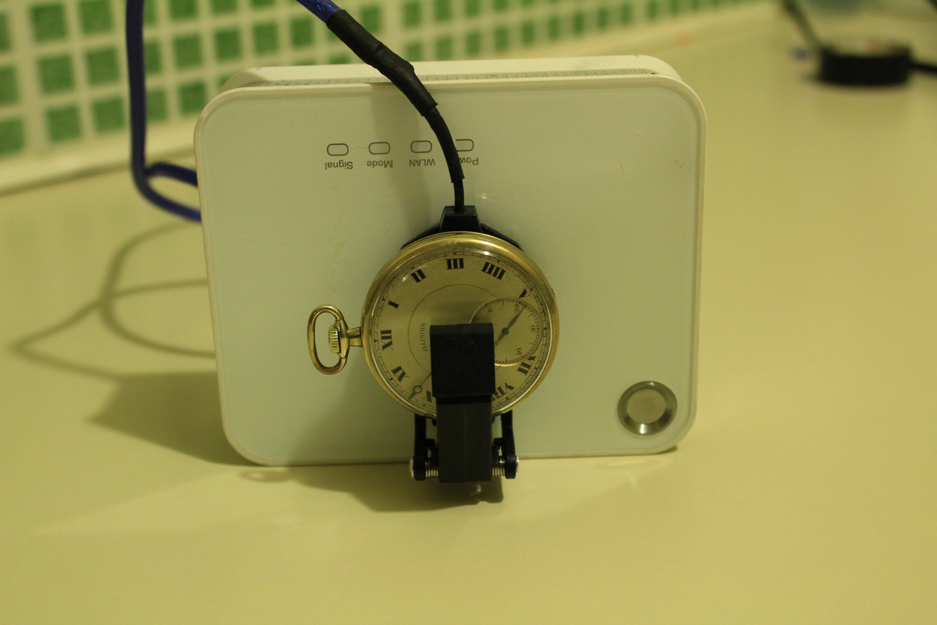
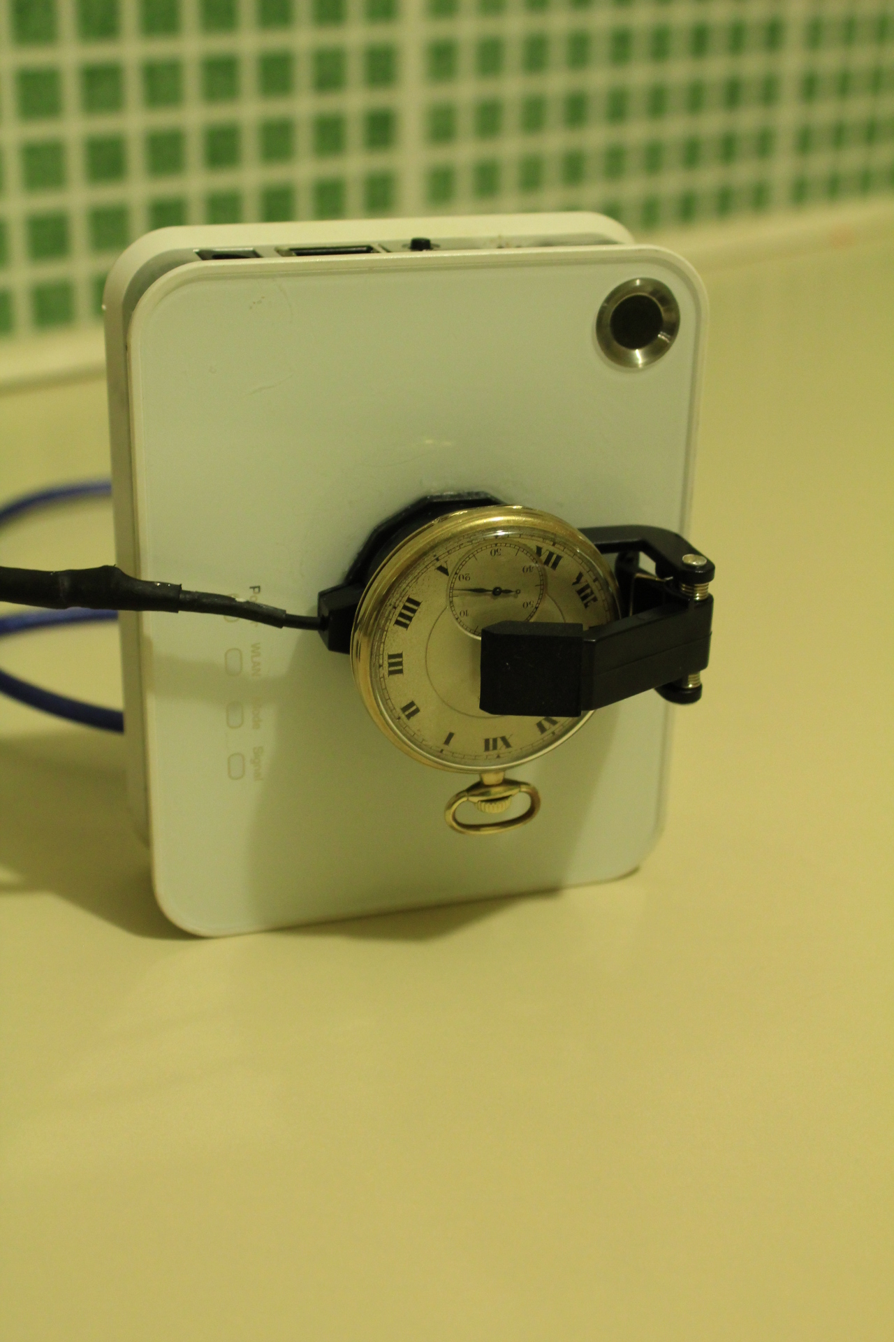
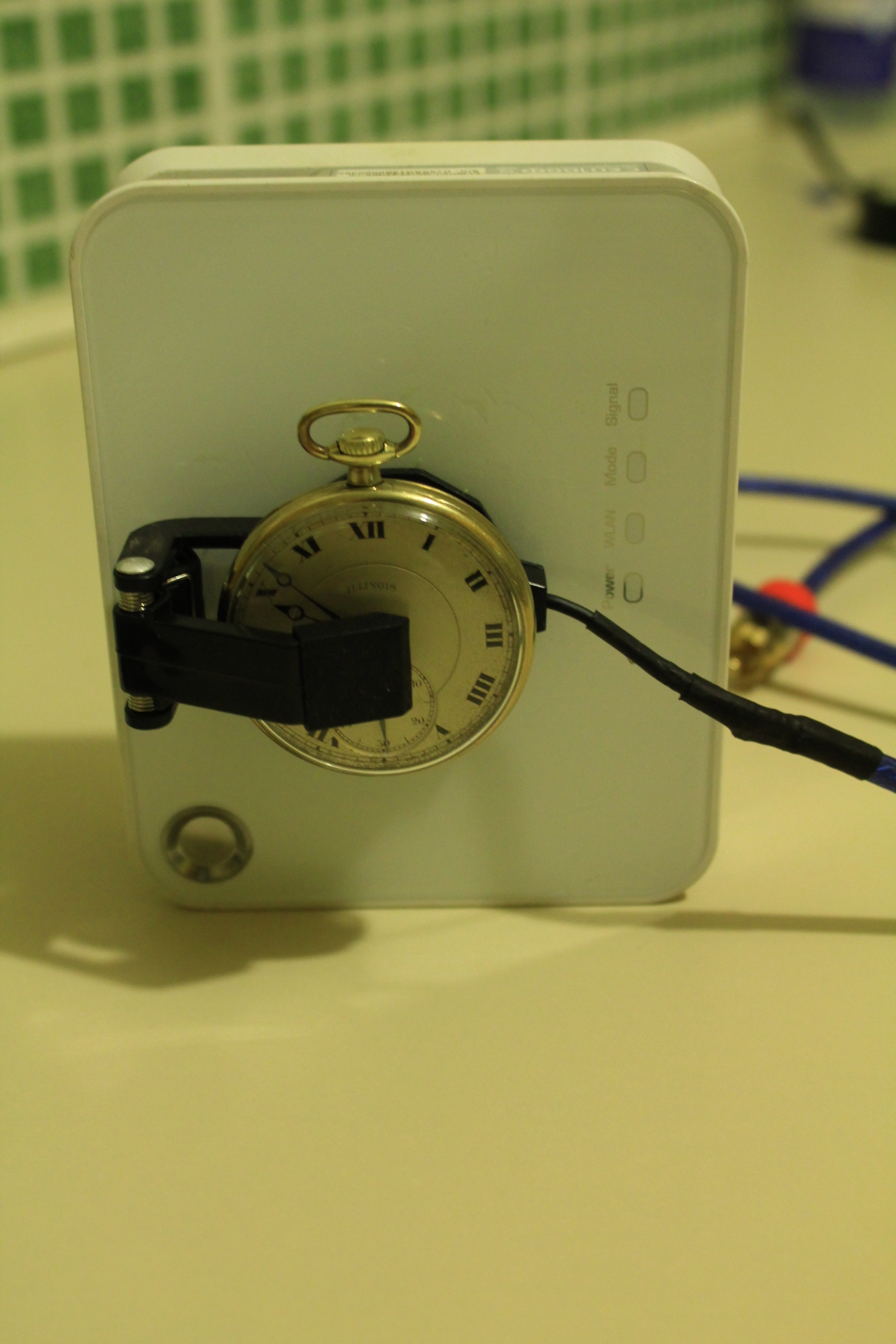
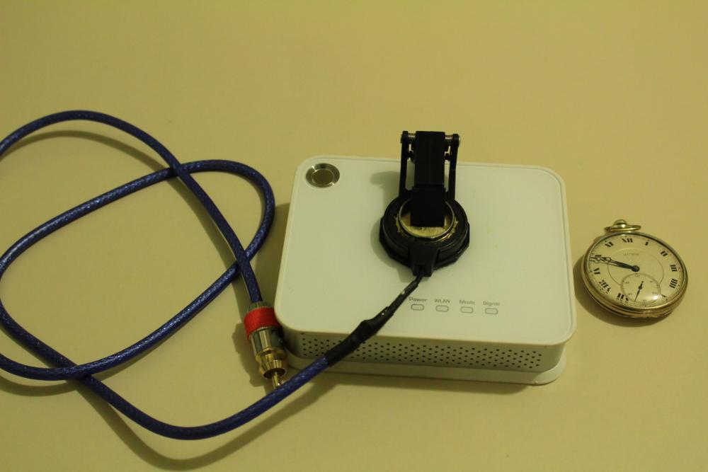
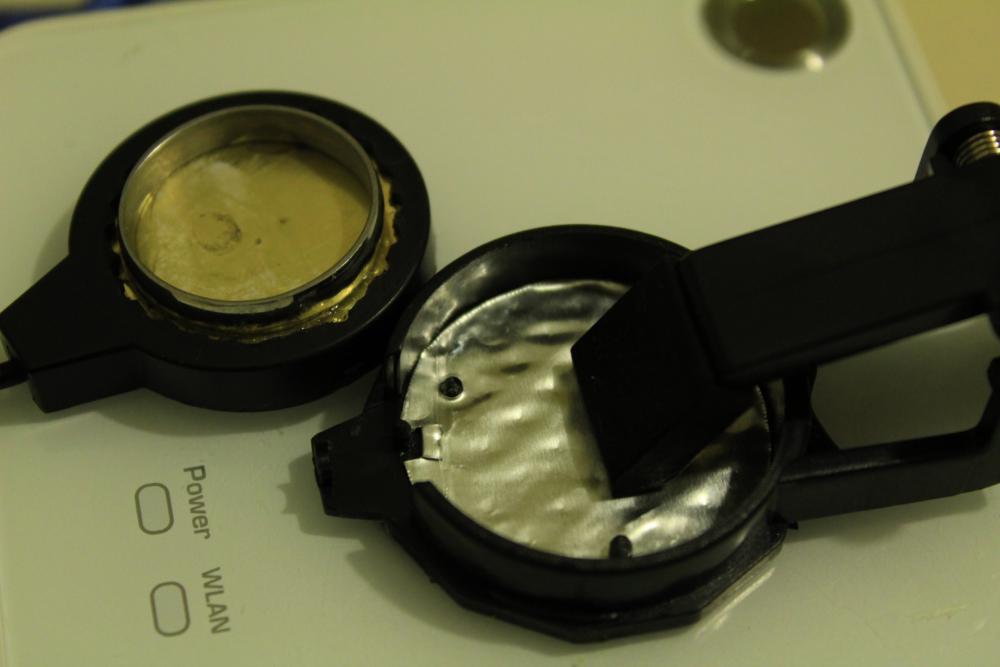
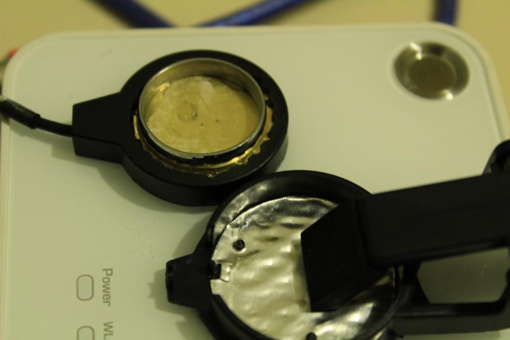
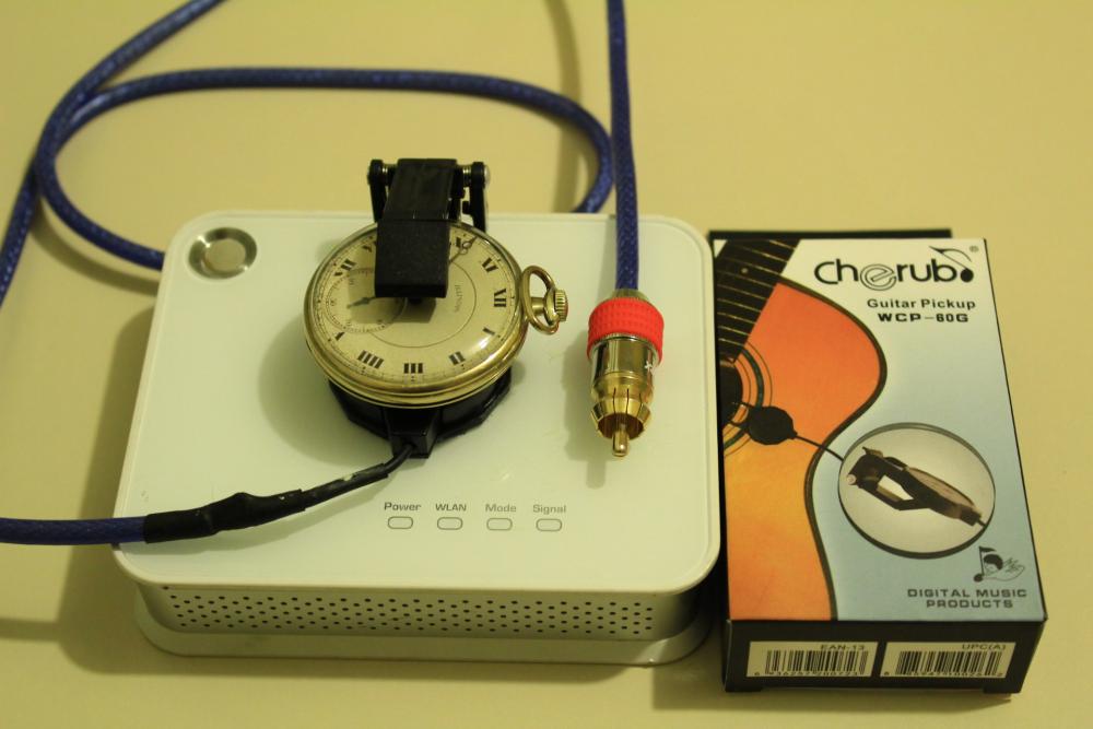
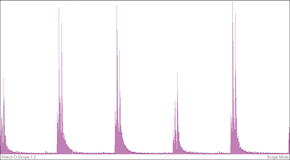
Congratulations. Good job. I would like you to share a sample of the sound recording in MP3 or WAV format. A few seconds. Also in screen capture "scope" mode. To display the signal / noise ratio. I am making some corrections in my microphone but I still regard being noise network of 60 Hz. Here I have this prototype. I used a microphone for guitar. Here we can see what is inside it. I made some modifications. How to change the cable for one with better shield. Recycle one moden only as support. There sticking with super-glue the microphone. Exposing the sensor surface with the help of a stainless steel ring. And that these are the top 5 positions in which the microphone works. Here a screenshot of the microphone signal. I used filtering digital Wide (160Hz- 16kHz. The Gear:


 1 point
 -
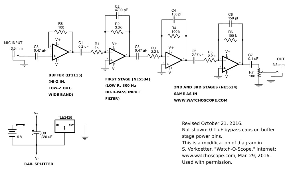
My previous attempts to lower noise in the preamp were flawed because I changed the bandwidth in doing so. The following circuit fixes this. There is an added buffer stage that uses an LT1115 op amp to isolate the microphone from the first amplification stage. Now the high-pass filter on the first stage does not depend on the capacitance of the microphone. I have it set for a frequency of 800 Hz (according to Stefan's comment of 800 Hz to 8 kHz being a good passband). I did not change the other high-pass filters to 800 Hz, but maybe I should have. The low-pass filters are all at 11 kHz, just as in the original Watch-O-Scope design. I built the circuit on my solderless breadboard. The measured noise was 6 mV, which should be compared to the 22 mV of the original circuit. I had a lot of trouble getting a buffer that was stable. I could not get the NE5534 op amp to work for this. It insisted on oscillating, even when I added the recommended 22 pF compensating capacitor across pins 5 and 8. My present circuit is still not perfect. It oscillates when the microphone (or signal generator) is unplugged from the input.
 1 point
 -
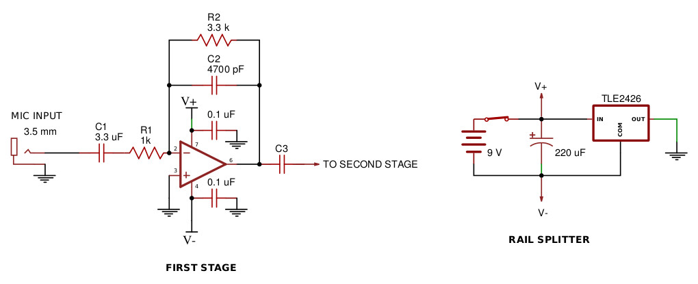
My latest version of the amplifier has only 3 mV of noise, compared to the original 22 mV. Probably good enough. I can barely hear the noise now. I made two changes. First, I changed to NE5534 op amps, which have much lower voltage noise. Second, I reduced the resistances in the first stage by a factor of 30 (and increased capacitances by the same factor) to reduce resistance noise. The diagram below shows the changes. There is no bypassing other than what is show here, on the first stage only. For details see my noise article at http://wlysenko.blogspot.com.
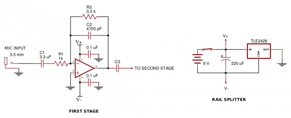 1 point