Jump to content

Recommended Posts

Posted

This is the dashboard clock my father pulled from his 1966 Chevrolet El Camino earlier this year. The clock didn't run at all and he asked me to take a look at it. Knowing nothing about automotive clocks I was intrigued and rushed over to pick it up.

261661044_IMG_21613.thumb.jpeg.fd4f28ae6c52cc73898bcb9a3c6582f6.jpeg

It's a simple affair with just two hands and a knob to adjust the time. No winding is necessary. On the back of the clock housing is a single 12 volt connection- the housing itself must ground the clock when installed in the dash.

IMG_2162.thumb.jpeg.82809c72c4a3df275c484e81ad004c55.jpeg

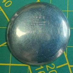
Stamped on the rear housing are the words Borg Instruments, Delavan Wis. The housing is removed by bending the three sheet metal tabs that run the circumference of the clock.

IMG_2163.thumb.jpeg.3550effc77366bf53986484fbb931dc6.jpeg

Inside is a delicious stack of gears and a solenoid which winds the clock.

IMG_2166.thumb.jpeg.ebd25ff47bd625b47ddb9252196affff.jpeg

A coil spring serves as the mainspring in this clock and it holds just about two minutes of power in it. When the coil spring is completely relaxed the two electrical contact points come together and are energized via the 12v connection. This causes the solenoid to act snapping the contacts away from each other and putting energy back into the spring. This action repeats itself every two minutes until the car battery is dead.

IMG_2167.thumb.jpeg.2e5986df451ed1e79110b7bac9f75ca4.jpeg

IMG_2174.thumb.jpeg.bef3a8963e1cf8aad3919a320bae825d.jpeg

Judging from the YouTube videos I watched before tackling this project- the typical failure point is the electrical contacts which wear out over time and fail to connect when the mainspring winds down. This wasn't the problem in my father's clock though. Most of the bearings in his clock had worn pear shaped and needed to be replaced.

I broke down the clock for a good cleaning before turning new bearing on the lathe. The movement only has two jewels (for the balance wheel) so it's not surprising that the bearings would give out eventually. Some of the pivots were worn too and needed cleaning up as well.

IMG_2179.thumb.jpeg.221839a12f563140e71a5295986456ce.jpeg

IMG_2181.thumb.jpeg.38571877e934abdcf9009aeb77a4fdec.jpeg

One of the cool things about this clock is that adjusting the time also regulates the speed of the clock. The setting knob is geared to make adjustment to the regulator and in this way whenever you make an adjustment 9adding or removing time) you are also adjusting the speed of the escapement.

IMG_2182.thumb.jpeg.9f147e9ce9416abc21c353c70565d417.jpeg

Everything was giving a nice scrub before reassembly. I removed the balance wheel in order to clean the plates and the hairspring is attached using shellac. This worried me a little bit but I found a narrow tip on the soldering iron was just perfect for softening the shellac and re-securing the hairspring.

IMG_2189.thumb.jpeg.7bd0b04e2115b92fd59ed93abe00f3b1.jpeg

IMG_2199.thumb.jpeg.318785d1f5a1e5aa75b3d72370af8736.jpeg

In the end I think I replaced five bushings in all.

IMG_2192.thumb.jpeg.eadbcda7cd2947ca00e8d5d918bcb6e4.jpeg

IMG_2201.thumb.jpeg.cd4aaf655737500bbf59347eca60f0a6.jpeg

IMG_2203.thumb.jpeg.21ff254f5e746cae17f3295b814854e4.jpeg

My father and I tested the clock by attaching it to the battery and letting it run for twenty-four hours; we found it to be a couple minutes slow the next day. I made an adjustment to the regulator before final installation in the dash and it seemed to be a bit better. Time will tell if it was a proper repair though. It was a fun little side project. I always assumed those dashboard clocks were entirely electrical but never bothered to considered how they worked. Now I know. ?

IMG_2234.thumb.jpeg.cff6db72df093a6968b3c3696c72957c.jpeg

  • Like 5
Posted

That must have been running dry for it to have all that wear, apart from the balance those types should be greased. The first types of car clocks used to be wind up.  

A nice walk through by you on how you went about the repair. Thank you so much. 

Posted

This post brought back memories.  That's practically the exact same movement that was in my old '76 Chevy Camaro.  Man, I miss that car.  It was a blast.  And yeah, with the clock I had to add a couple bushings, and I made a new brass contact, a bit of grease, and then it worked fine.  And it was fairly accurate too.  I remember you always knew the clock was working because, every now and then, you'd hear the solenoid quietly go *thunk*.  I wish I still had pictures of that car.  It was a hot rod by the time I got done with it.

  • Like 1
Posted

Cool!


I always assumed these were just driven by a 12 volt motor. But, it makes sense it wouldn't be, because at rest, the car voltage is around 12 volts and it goes up to about 14.5 when charging the battery. That's a big swing, and the timing would be quite erratic. De-coupling the movement from the (electrical) power takes away that influence. Quite clever.

Now I'm sure a voltage regulator on a chip drops to nine or six volts, which remains as long as battery power is above the output voltage of the regulator. I have a VDO clock in my Defender that is reasonably accurate (might be quartz?) but also quite noisy... I had thought about dismantling and cleaning & oiling it to keep it quieter than the turbodiesel under the hood.

  • Recently Browsing

    • No registered users viewing this page.
  • Topics

  • Posts

    • I believe @nickelsilver has a setup like that.
    • I posted pictures earlier in this thread. My lathe and mill are two separate instruments. I think I have seen examples of putting a milling head on a lathe bed...but not certain.
    • Timex Camper, September 1994, new to me. Strap is an old perlon with "Germany" in script etched into the resin on the tail end. Not Horlon or Eulit I believe. History unknown, running strong, losing less than a minute a day. Goals for this: Wear it a ton! Buy crystal lift, clean out the gunk around the ring and under the crystal Eventually swap into a stainless steel case. I've seen a member who has swapped a Timex mechanical movement into the Timex J.Crew quartz field watch case.
    • One of the problems we would have with a watchmaker's lathe is they were made over considerable span of time and manufacturing in the early days probably wasn't as good as it was today. Then if you look at the older catalogs typically it was just the head a few collets and something to rest graver on. So basically a basic lathe with over time things acquired but acquired things may or may not fit. Order today you purchase a used lathe that all kinds of nifty bits and pieces from a seller that acquired from? This would come back to that the basic watchmaker's lathe was used for basic watchmaking like turning things with a hand graver. Then limited indexing is fine because you can make things like stems Which don't need a whole bunch indexing   In the link above the word vector is mentioned and at the link below you can purchase one. Then of course you're going to need the motor that's a little bit extra for the price. https://www.hswalsh.com/product/lathe-vector-watchmakers-48-collets-hl11. That you're going to need some bonus parts like these found this picture online show the classic way of classic gear cutting.   The lathe could have a much bigger indexing disk but it has to be mounted close to the edge. Otherwise you're going to have a whole bunch of smaller disks like this which I think has notches rather than holes. Then as wonderful as these pictures look actually cutting a gear with this is not entirely fun. Look at all is belts all pulling on things and this is a watchmaker's lathe lightweight with lots of bits and pieces attached. It would make more sense if you actually cut a gear with something like this and it tends to be it's not really the best way to do it looks nice on paper but it is not the best way to go. Reality for cutting watch parts would be a bigger machine is much better. Than getting rid of all those belts and pulleys also good. Here is an interesting channel I would've liked of found a different video but this was nice and short if you look at his video as he uses a stepping motor and worm gear assembly for the indexing plate. In this particular video it gets attached to the lathe at about one minute and seven seconds and it looks like it's hiding looks like he has a Sherline. I do know he's had other stuff you'll just have to go through his videos to find it. Then at about one minute and 22 seconds you find out if you set up things appropriately. It's always bad we end up with half a tooth at the very end. Then you will note big lathe yes he's getting a big gear but you could easily cut a watch gear with the setup. And it definitely way more stable than a watchmaker's lathe.         Oh here's a company they been in business since 1911 http://www.fwderbyshireinc.com/  
    • Hello and welcome from Leeds, England. 
×
×
  • Create New...