Leaderboard


Popular Content
Showing content with the highest reputation on 07/29/18 in all areas
-
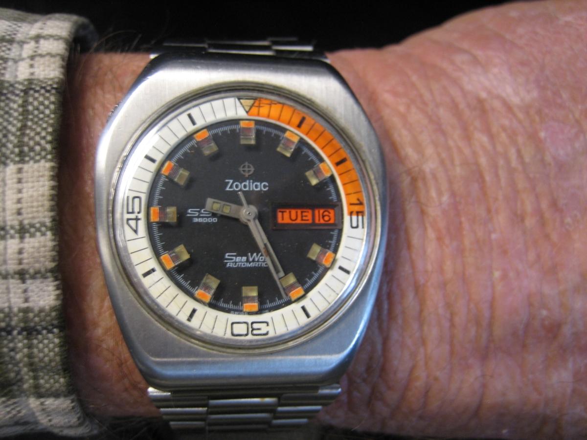
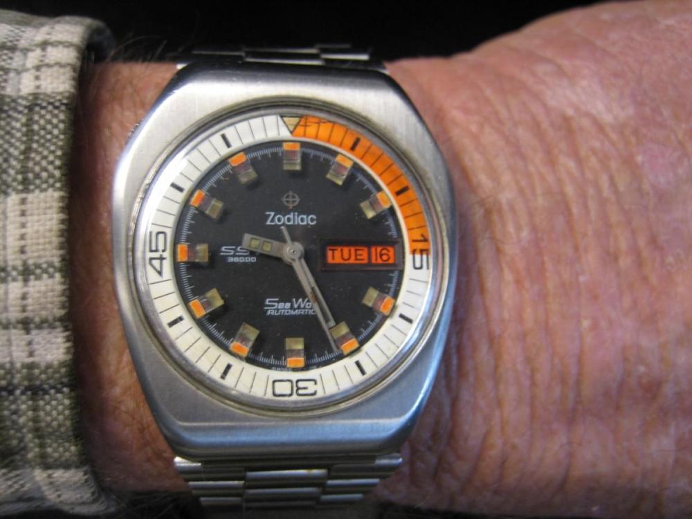
Thought I would post my first new watch... This was the first thing I bought when I came aboard the USS L.Y. Spear as a young Seaman back in 1974. I still wear it regularly, in rotation with my other watches...
 1 point
 -
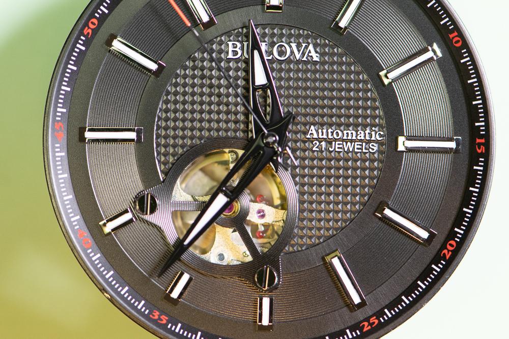
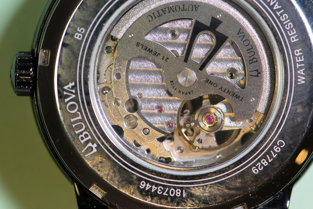
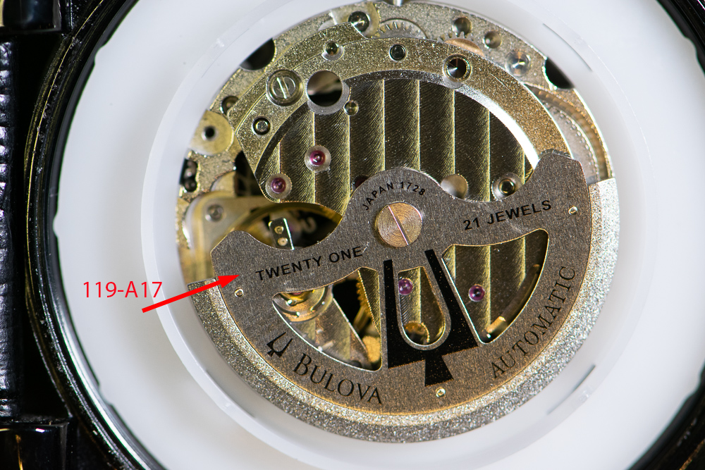
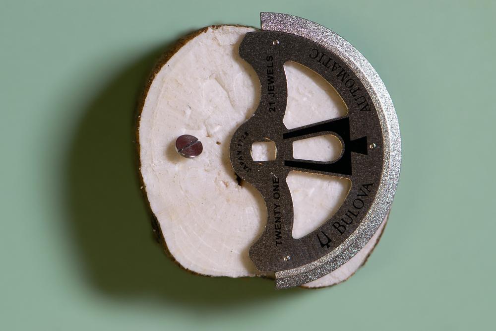
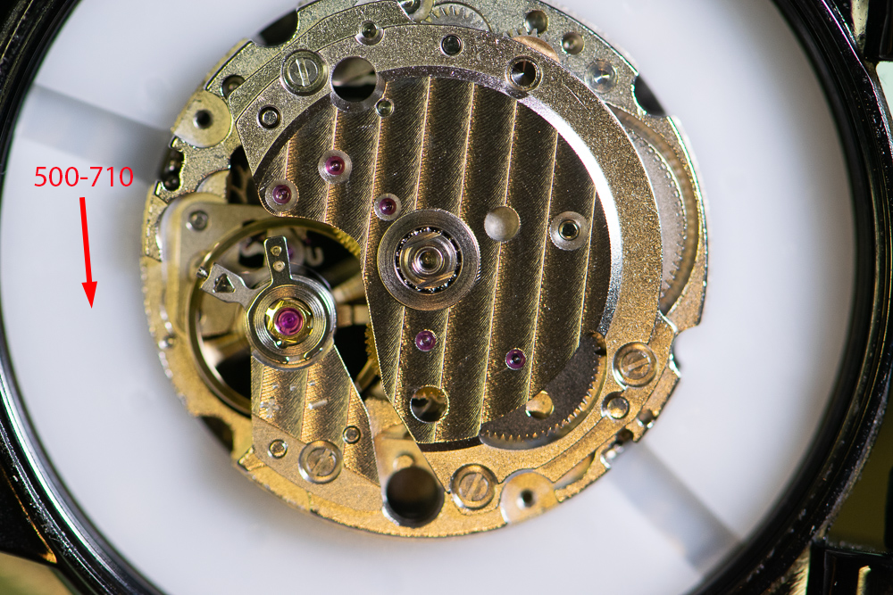
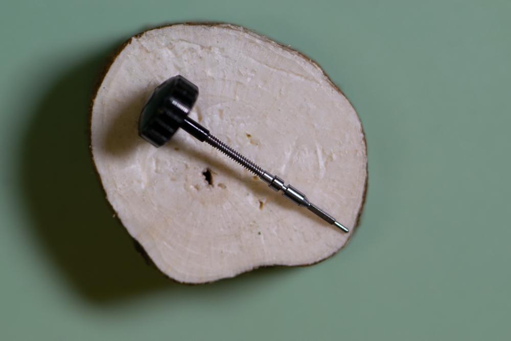
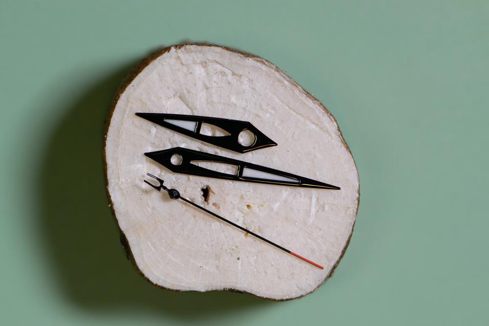
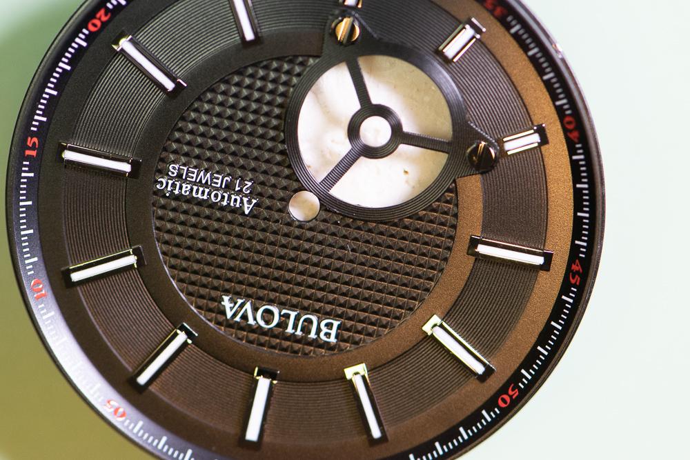
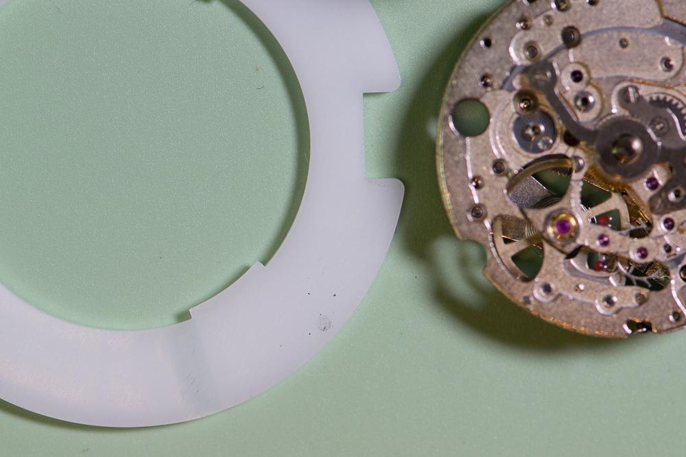
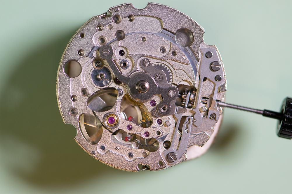
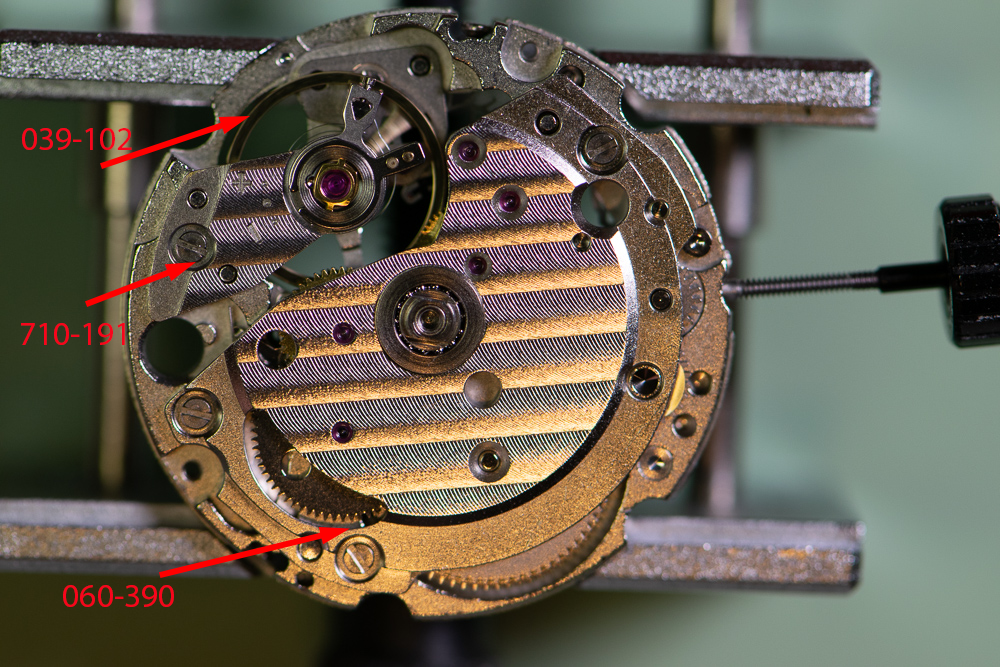
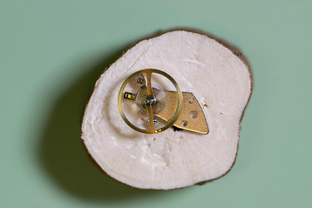
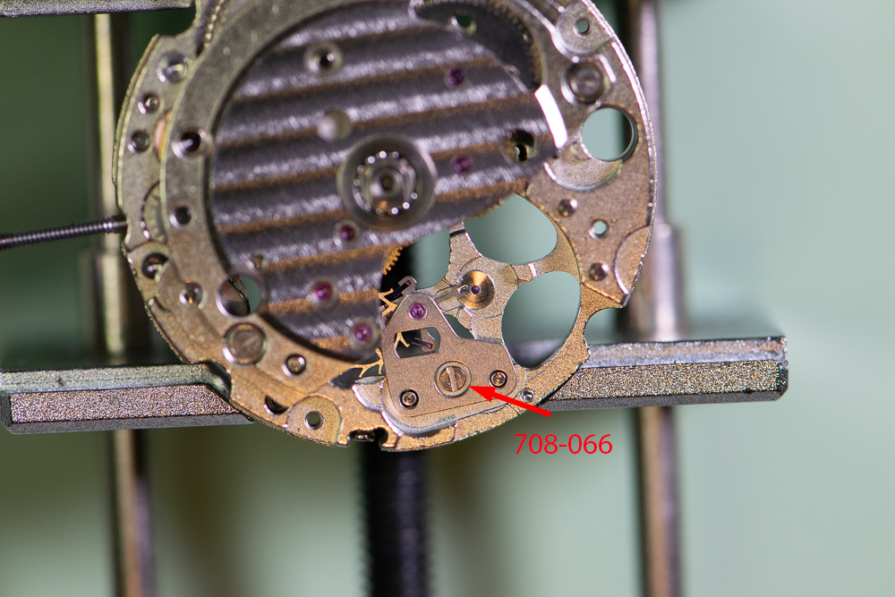
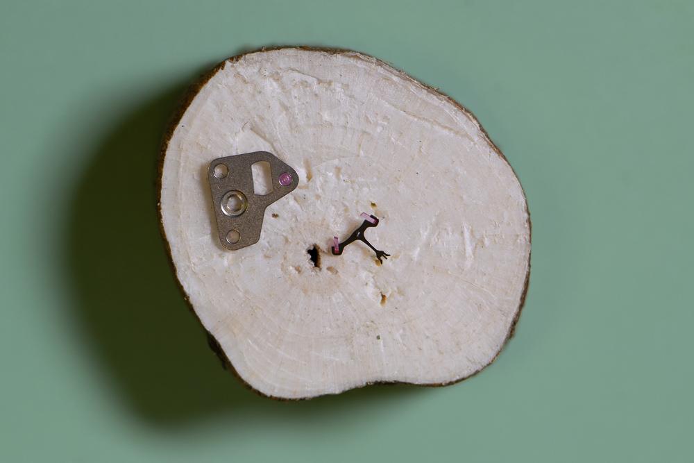
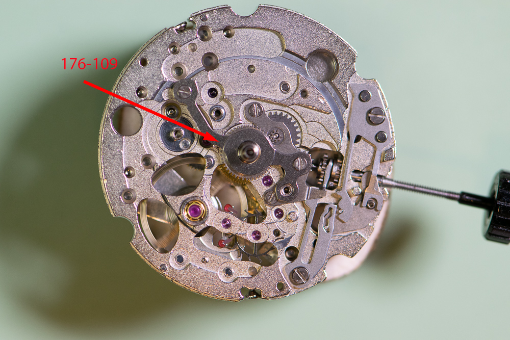
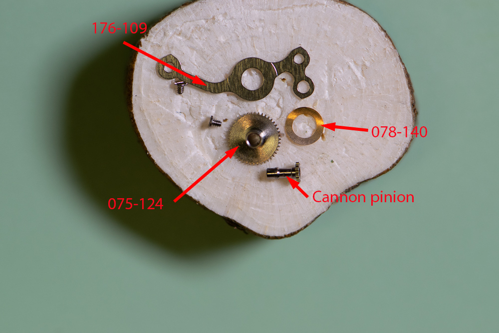
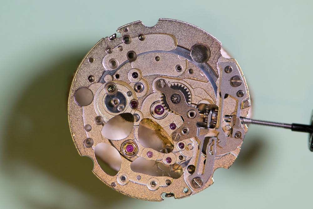
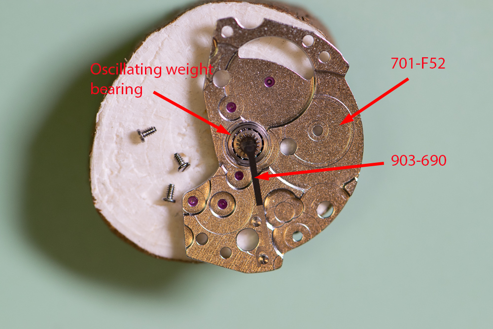
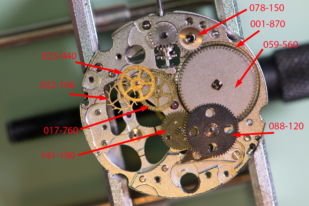
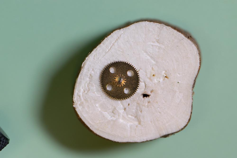
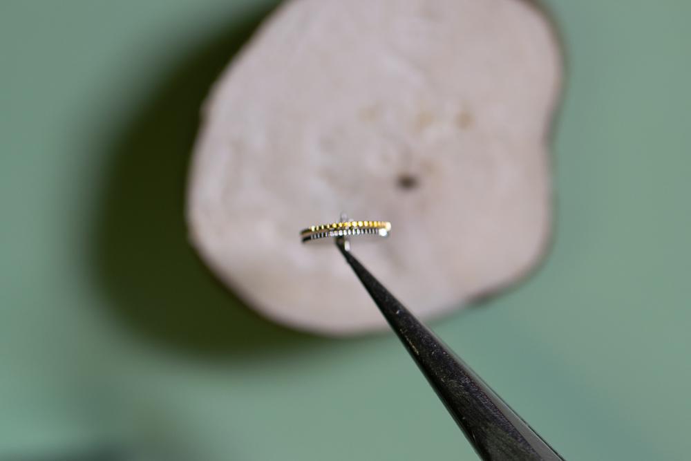
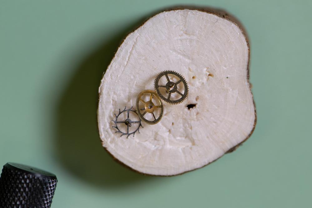
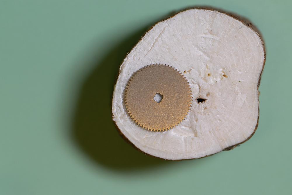
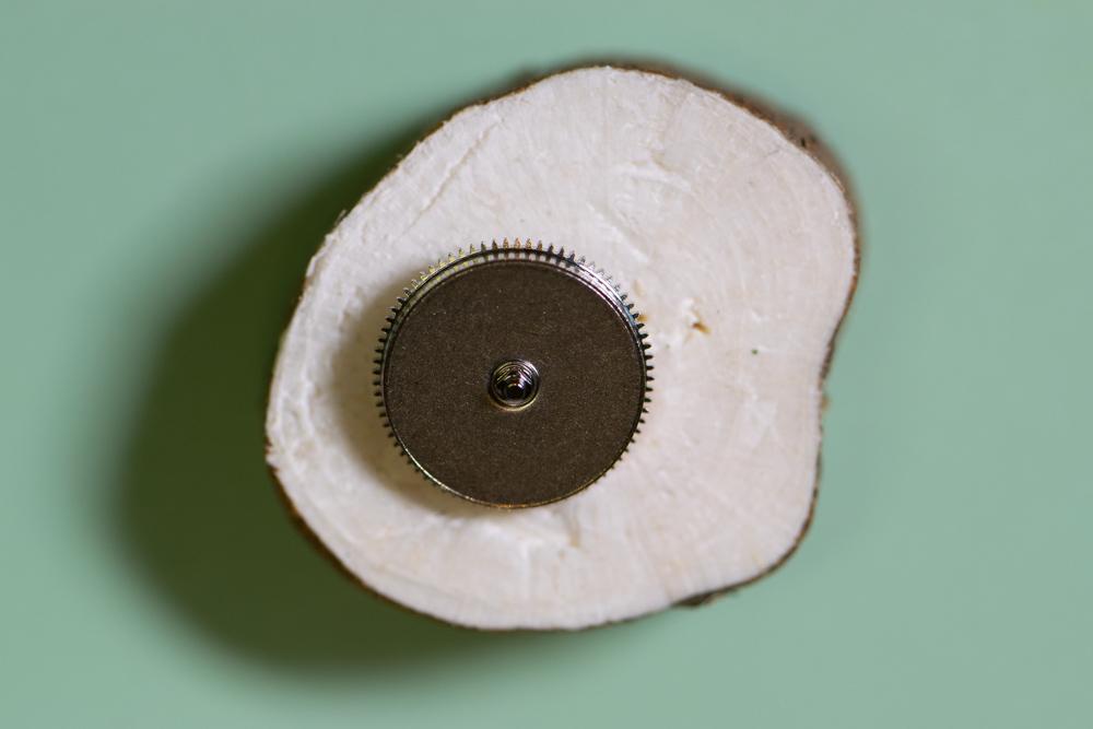
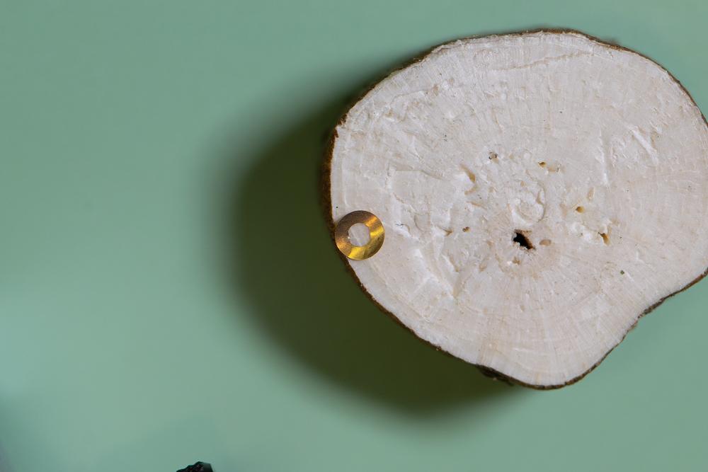
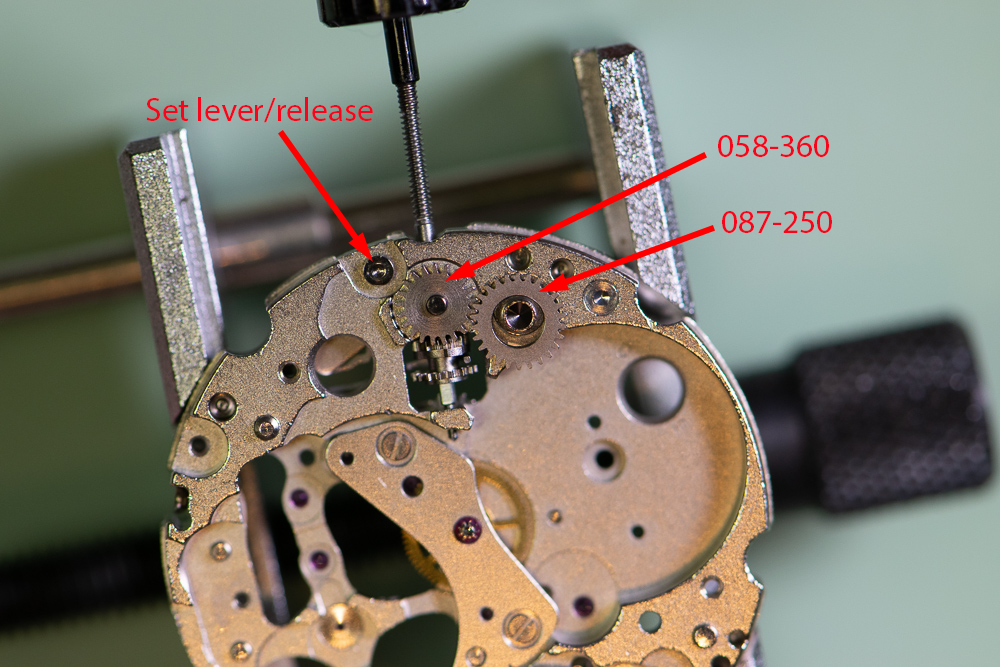
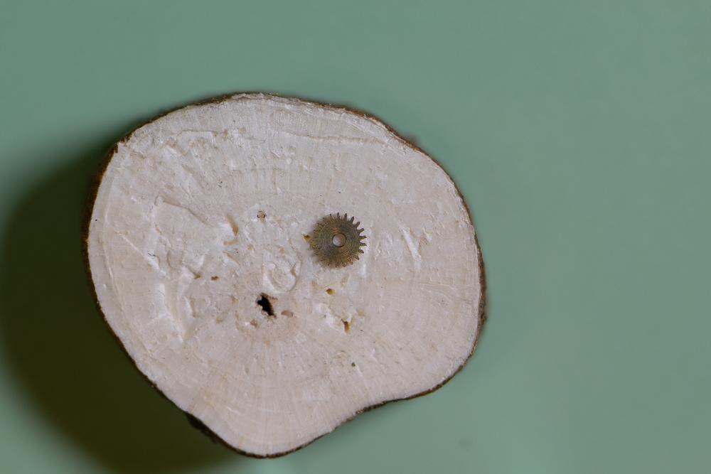
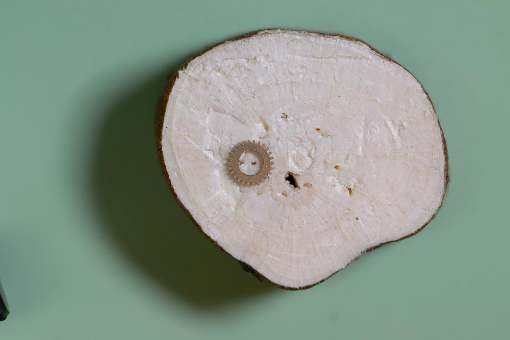
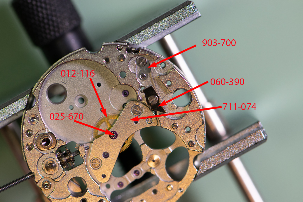
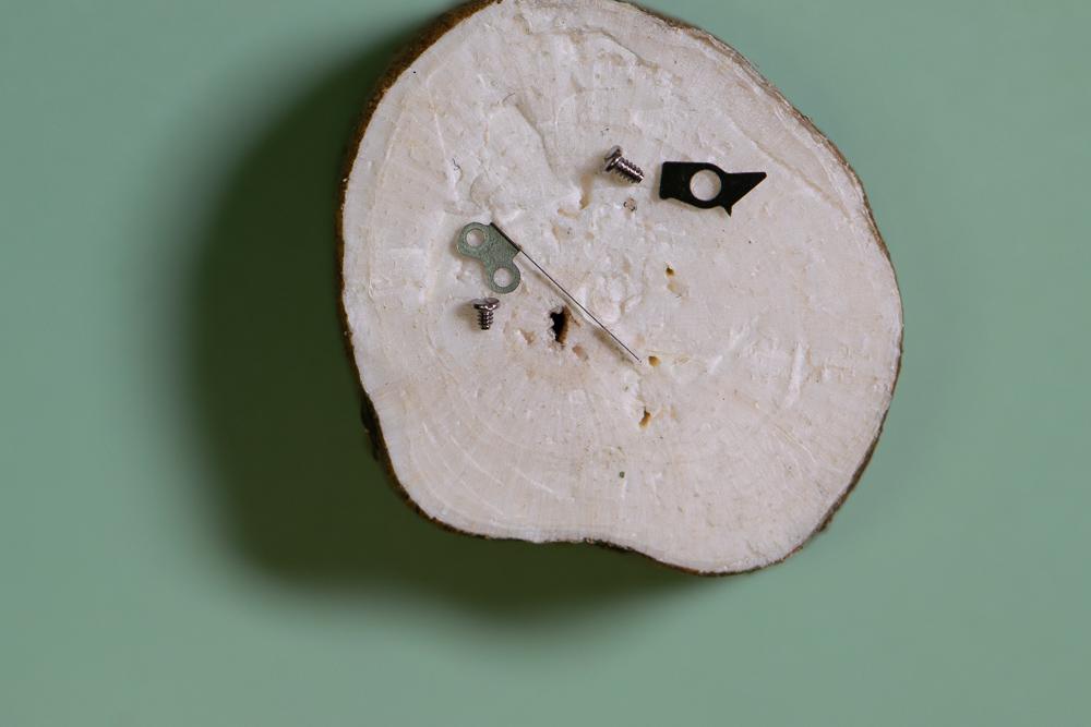
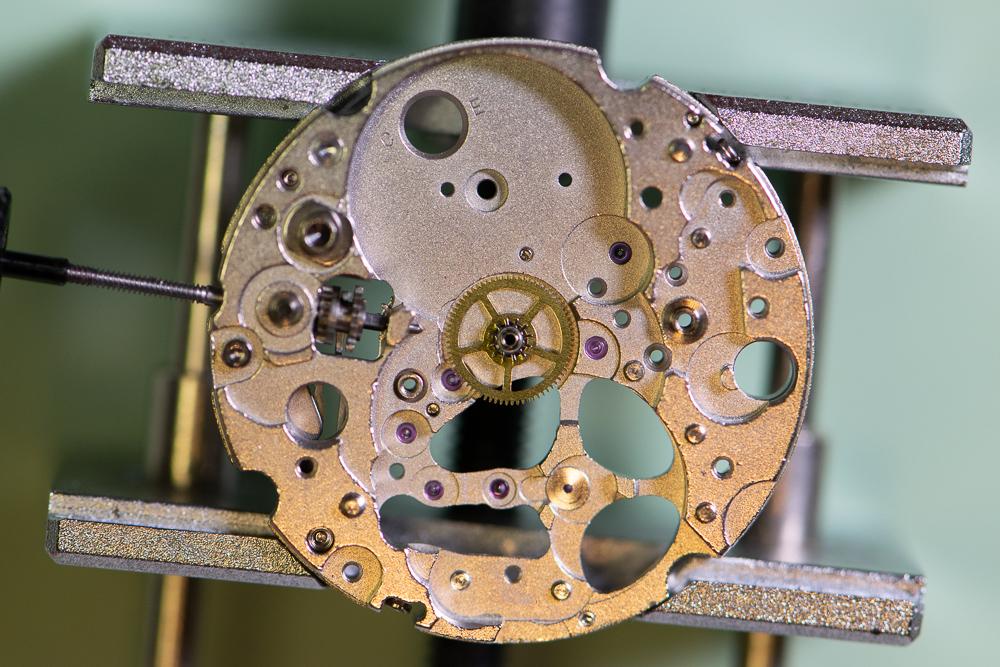
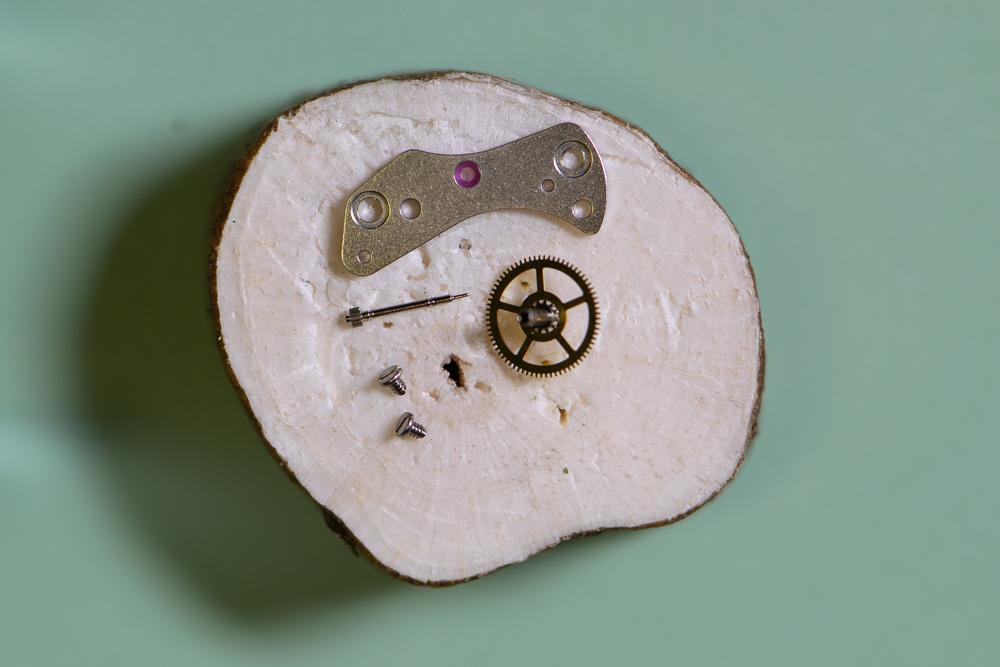
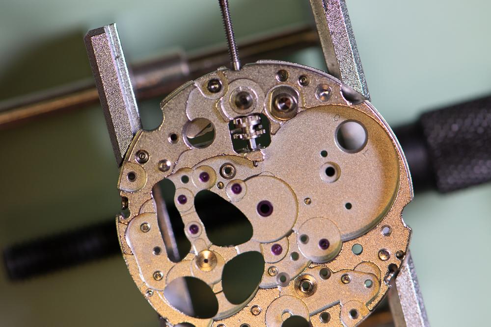
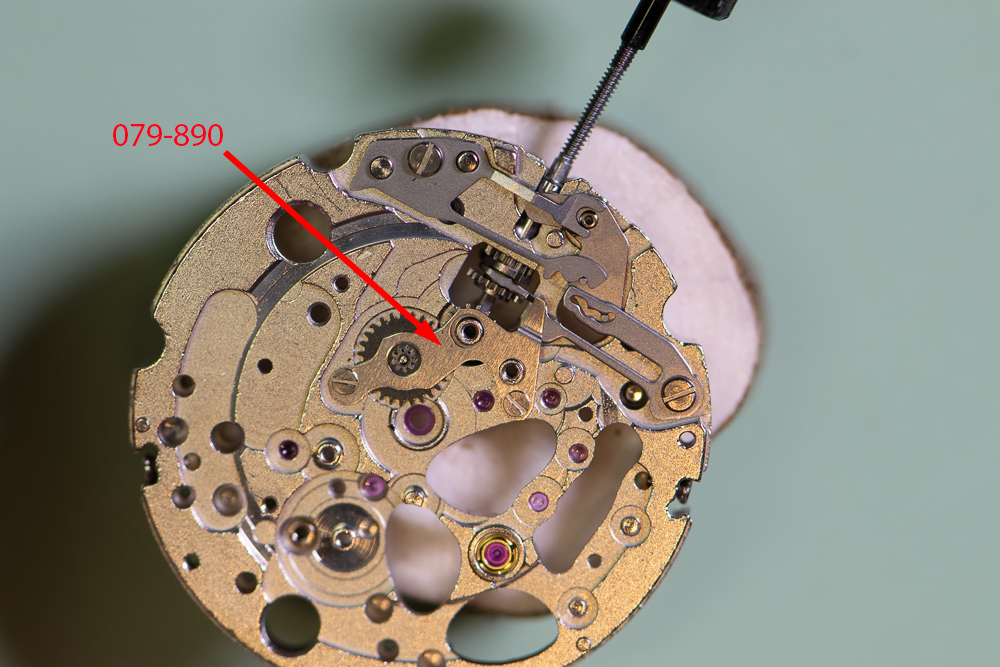
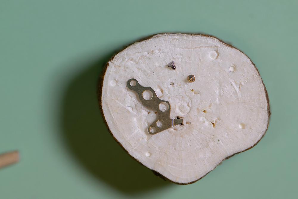
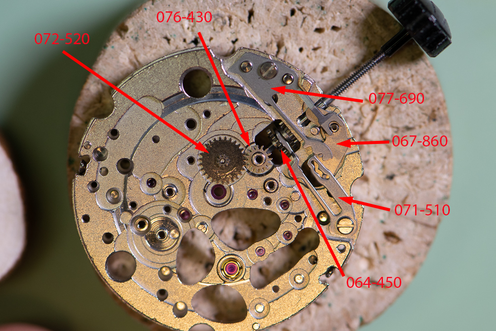
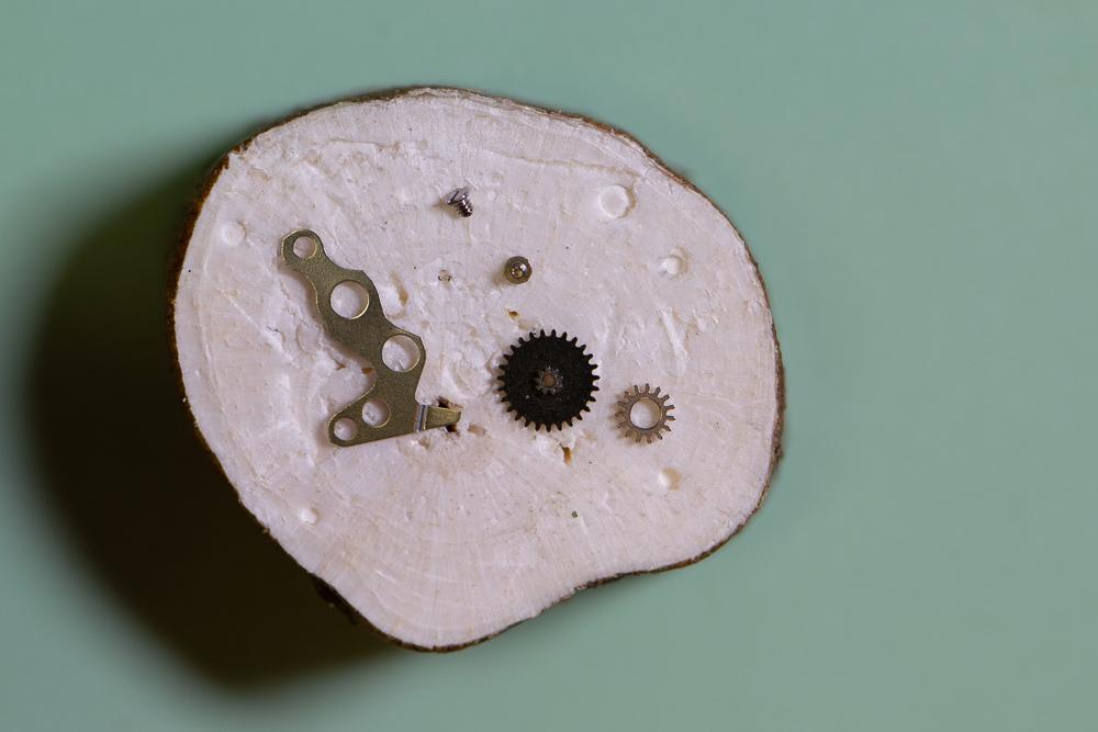
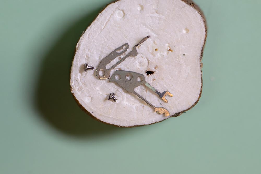
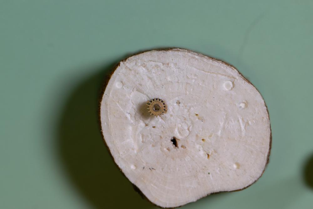
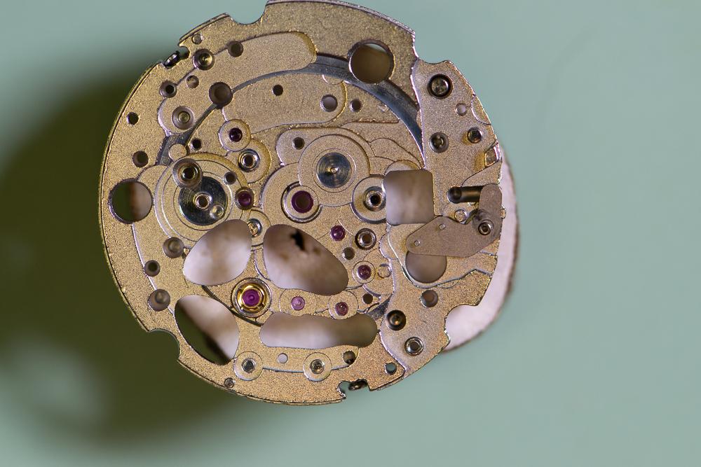
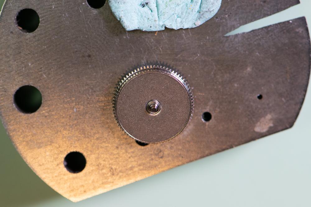
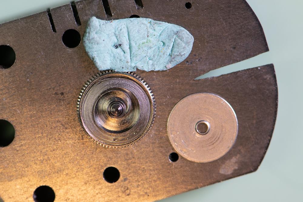
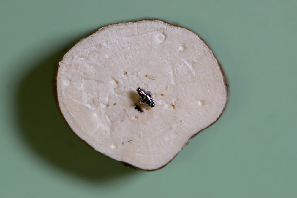
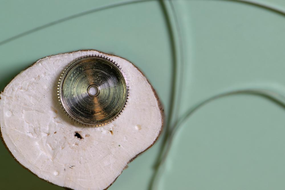
This is a more detailed version of my previous picture-only post for this watch. This Bulova 21-jewel automatic was given to me by a colleague for repair. It was running extremely fast – gaining about 15 minutes per hour. The movement is a Citizen/Miyota 82S0 skeleton. Looking through the clear back it was obvious that the balance amplitude was extremely low. First step was to simply demagnetize the watch to see if that did the trick as it sometimes does. No dice. I then removed the balance and pallets and put a small amount of wind onto the mainspring. The train spun up but as power wore off the escape wheel stopped, then started again several times. It was a very sloppy action. Nothing obvious in terms of loose or cracked jewels or excessive side or end shake that I could see. I decided to disassemble the movement and give it a full servicing. Here is how I disassembled the movement. Where I can I will list the Miyota part number for reference. You can find the parts list here: http://miyotamovement.com/parts_search.php?open=82S0 Figure 1 shows the face of the watch after removing from the case. Note the exposed balance at the 7 o’clock position. Figure 1 – Face Figure 2 shows the clear case back prior to removing the movement. Figure 2 – Case back The first step in disassembly is to remove the Oscillating weight (119-A17. Note that the weight is secured to a bearing that is pressed into the main plate. Unlike many Swiss movements, the screw securing the weight rotates with the weight itself. I used a peg wood stick to prevent the weight from rotating while unscrewing the fastener. Figure 3 shows the weight prior to removal. Figure 4 shows the oscillating weight after removal. Figure 3 – Preparing to remove the oscillating weight Figure 4 – Oscillating weight Figure 5 shows the movement after removing the oscillating weight. The plastic movement holder (500-710) is also visible. This will be removed after dealing with the hands and dial. I also removed the winding stem (figure 6) by pressing in on the setting lever and gently pulling the stem. The location for pressing on the setting lever was clipped from the pic, but it’s a standard setup. Figure 5 – Plastic movement holder Figure 6 – Winding stem After removing the stem, the movement was removed from the case. The stem was then reinstalled to facilitate power let-down, etc. With the oscillating weight removed, it’s a simple matter to lay the movement down dial-up on a piece of pith wood and remove the hands (Figure 7). The dial retaining screws on the side of the movement are loosened (not removed) and the dial is gently coaxed away from the movement by inserting a thin screwdriver blade. Figure 8 shows the dial after removal. Figure 7 – Hands Figure 8 – The Dial The movement holder shown in figure 5 is now lifted off. It is shown in figure 9 next to the movement. Figure 9 – Movement holder ring Figure 10 shows the dial side of the movement. Figure 10 – Dial side The movement is then flipped dial down and loaded into a movement holder for disassembly. The balance (039-102) is removed along with the balance bridge (710-191) as shown in figure 11. Figure 11 – Preparing to remove balance The balance complete is shown after removal in figure 12. Figure 12 – The balance complete Important: Before removing the pallets I need to remove all the power from the mainspring. I do this in the standard way – by applying a bit of winding pressure on the crown while pulling the click (060-390 in figure 11) out of the way with a bit of peg wood and allowing the stem to unwind in a slow/controlled manner. Figure 13 – About to remove pallets With the power let down I can now remove the pallet bridge (708-066) and pallets. Figure 13 shows the bridge prior to removal. The pallets and bridge are shown in figure 14. Figure 14 – Pallets and pallet bridge I probably should have removed the motion work prior to starting in on the balance – not sure why I didn’t. Regardless, we need to flip the movement back so I can remove the motion work from the dial side. The hour wheel is held in place by the hour wheel spring (176-109). Remove the 2 retaining screws and then lift off the spring. The spring is shown prior to removal in figure 15. Figure 15 – Hour wheel spring prior to removal Once the hour wheel spring is out of the way I can remove the dial washer (078-140), the hour wheel (075-124) and finally the cannon pinion (using your favorite cannon pinion removal tool). These parts are shown after removal in figure 16. Figure 16 – Hour wheel spring, hour wheel, dial washer and cannon pinion Figure 17 shows the movement after removal of the motion work. It’s now time to flip the movement back over and start in on the gear train. Figure 17 – After removing the motion work I remove the three screws securing the barrel and train wheel bridge (701-F52) and carefully remove it. Figure 18 shows the underside of the bridge. Note that the seconds pinion friction spring (903-690) was left in place. I didn’t see the point in removing it. You can also see the oscillating weight bearing that is press fit into the bridge. I didn’t mess with this either! Figure 18 – Barrel and train wheel bridge and seconds pinion friction spring Figure 19 shows the detail after removing the barrel and train wheel bridge. First, I remove the reduction gear (088-120) and reversing wheel (141-190). These components are part of the automatic winding mechanism. They are shown in figures 20 and 21 after removal. I make note that the reversing wheel should be installed with the brass side up. Figure 19 – After removing barrel and train wheel bridge Figure 20 – Reduction gear Figure 21 – Reversing wheel Next, remove the third wheel (017-760), fourth wheel (023-940) and escape wheel (032-106). These are shown in figure 22. Figure 22 – From left to right – escape wheel, fourth wheel and third wheel Next, I remove the ratchet wheel (059-560) and the barrel complete (001-870), which sits directly underneath the ratchet wheel. Th.ese components are shown in figures 23 and 24. Figure 23 – Ratchet wheel Figure 24 – Barrel complete Looking back at figure 19, you can see a spring, very similar to a dial washer. This part is called the ratchet sliding wheel spring (078-150). Simply lift it off (figure 25). Figure 25 – Ratchet sliding wheel spring With the spring out of the way I can now see the ratchet sliding wheel (087-250). I remove this part along with the crown wheel (058-360). Figure 26 shows these parts. Ah – finally a picture that shows the setting lever release button I mentioned earlier! Pressing here allows the stem to be removed. I will leave the stem in place for now. Will get to it shortly. Figures 27 and 28 show the parts just removed. Figure 26 – Crown wheel and ratchet sliding wheel Figure 27 – Crown wheel Figure 28 – Ratchet sliding wheel Figure 29 shows the click (060-390) and click spring (903-700), the center wheel cock (711-074), center wheel (012-116) and center seconds pinion (025-670). Technically I believe the center wheel cock should be named the center wheel bridge since it’s secured by more than one screw, but I’ll leave that open for debate. Tension on the center seconds pinion is provided by the friction spring we saw back in figure 18. Figure 29 – Click and spring, center wheel and cock, center seconds pinion Figure 30 depicts the click and click spring after removal. Figure 30 – Click and click spring Figure 31 shows the center wheel in place after the center wheel cock has been removed. Figure 31 – After removal of the center wheel cock Figure 32 depicts these parts after removal. Figure 32 – Center wheel cock, center wheel and center seconds pinion The train side of the movement is now fully stripped. This is shown nicely in figure 33. Time to flip it over and finish off the dial side. Figure 33 – Finished with the train side Figure 34 shows the current state of the dial side of the movement. To get started I remove the minute train cover (079-890). Figure 35 shows this component after removal. Figure 34 – Dial side Figure 35 – Minute train cover I can now remove the keyless work. The components are shown in figure 36. The minute wheel (072-520) and setting wheel (076-430) are removed first. These components are shown in figure 37 along with the minute train cover. Figure 36 – Keyless work components Figure 37 – Minute and setting wheel Referring back to figure 36, the next components to remove are the yoke (071-510) and setting lever spring (077-690). The stem can now be removed and then the clutch (064-450) is free to remove. The setting lever (067-860) was not removed as it’s press button is staked (spread). No sense disturbing this. Figure 38 shows the yoke and setting lever spring after removal. The clutch is shown in figure 39. Figure 38 – Yoke (left) and setting lever spring Figure 39 - Clutch Finally, the main plate is fully stripped. The dial side is shown in figure 40. Figure 40 – Main plate – dial side We can now deal with the barrel assembly (figure 41). Figure 41 – Mainspring barrel complete Using the steel anvil for support, gently press down on the gear teeth to pop the barrel cover off (figure 42). Figure 42 – Barrel cover removed Carefully remove the barrel arbor (figure 43). Figure 43 – Barrel arbor Unwind the mainspring from the barrel (figure 44). Figure 44 – Barrel with spring removed This completes the disassembly of the movement. My next step will be to clean it in the ultrasonic. Will post the reassembly as a new thread.
 1 point
 -
I thought I’d show you this clock that is on ebay. I happen to like this, unusual colour with a nice dial, fits perfectly into the case. Good fusee strike movement. All in good condition. https://www.ebay.co.uk/itm/Rare-Antique-18thc-English-Green-Lacquered-Bronze-Twin-Fusee-Bracket-Clock/173435121142?_trkparms=aid%3D111001%26algo%3DREC.SEED%26ao%3D1%26asc%3D53380%26meid%3D3af6c854d54544f5905279e8b5b886a0%26pid%3D100033%26rk%3D3%26rkt%3D8%26mehot%3Dpp%26sd%3D372383999711%26itm%3D173435121142&_trksid=p2045573.c100033.m20421 point
-
There is no film on them. At least i don't think so. Maybe you can oil them slightly and then wipe it of. But that you need to do very time you use them. It's probably carbon steel tweezers you have?1 point
-
By chance found these interactive disassembling/assembling guides for some ETA movements.1 point
-
Hi and thanks for all this valuable info. You obviously dived deep into this field of buying/servicing/collecting russian watches. The historical aspect of our hobby is something I find very rewarding. The mechanical watch development based on the Swiss technology and spreading out in various geographical (and political) directions is an entire industrial epoque in itself that came to a semi-standstill with the introduction of the cheap quartz technology. This obviously except for the continuation in high-end brands making ”mechanical” into a sales argument. On a related topic I learned from a collecting friend that one can find NOS watches from (I think) the early 80’s from Chinese sellers that are quite interesting from this aspect. These watches made for the domestic market have apparently been sitting on the shelves in China since those days, when the quartz revolution made them impossible to sell, even on the local Chinese market. My friend bought a ”bucket” of them a couple of years ago for very low prices and I helped him getting a few running as they had dried up completely. The one I kept as compensation for the work is running increadably well while being very basic when looking at the details with your ”swiss glasses” on. Now I realize that these watches are (as one could expect) also becoming collectibles and prices are going up by the day. The fun never lasts, does it... :-) Sent from my iPad using Tapatalk1 point
-
Pops right out , pushed back on with friction Sent from my ONEPLUS A6003 using Tapatalk1 point
-
Will do! Not in a while though, vacation time in hot burning Sweden right now. Sent from my iPad using Tapatalk1 point
-
The first is a genuine 8-day fusee with chain wall clock with anchor escapement. One fixing peg has been replaced. The key I would suggest changing. These clocks are easier to wind with a crank key. The second is a genuine 8-day fusee with steel line wall clock with anchor escapement. One fixing peg missing. Don’t see any key. The plaster of Paris needs to removed and replaced inside the bezel. Both dials are poor and would need restoring. You have to be careful with the bottom opening doors, you will find many locks do not open, keys lost. Due to the moving parts and movement of the pendulum the doors tend to open on their own, some are so loose they will not close shut. The side doors also need to be looked at, hinges get broken, wood warping due to heat or dryness do not close properly. The first one is the one I wold go for.1 point
-
On the keyless side, make sure the spring is set on the 'combined setting lever jumper' (445/2) against the 'yoke' (435).1 point