Leaderboard


Popular Content
Showing content with the highest reputation on 07/27/18 in all areas
-
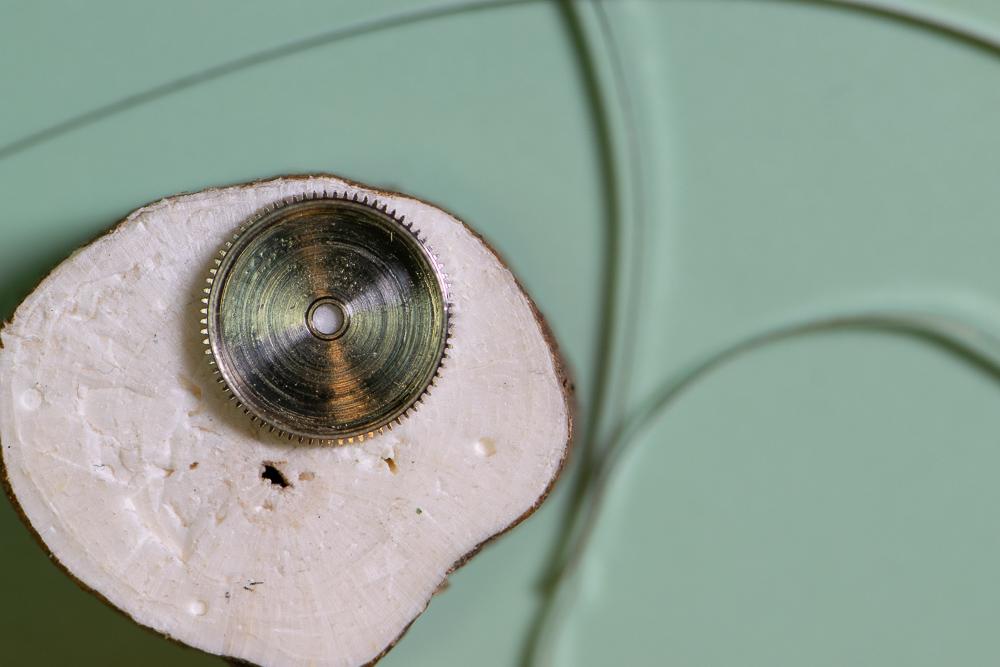
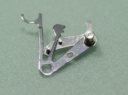
If you look at the bergeon tool in the video the "fingers" pull back, no center screw. Makes sense. The tool in the pics presses in the center, almost certainly a clock hand puller (or small gears etc. where pressing on a shaft while pulling around it makes sense).2 points
-
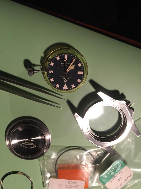
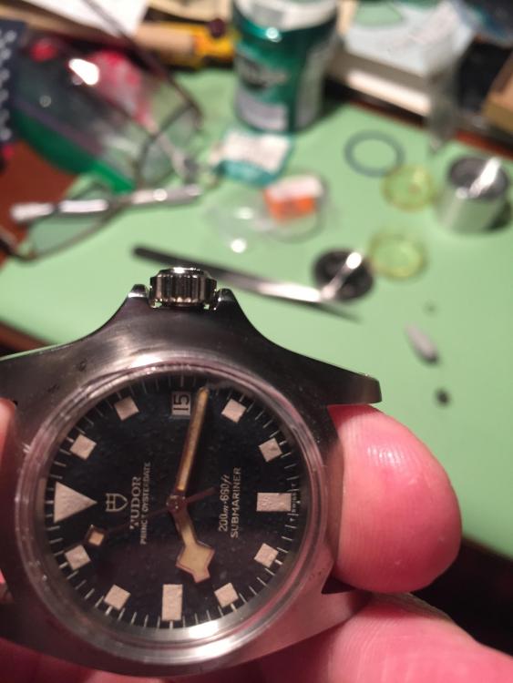
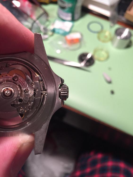
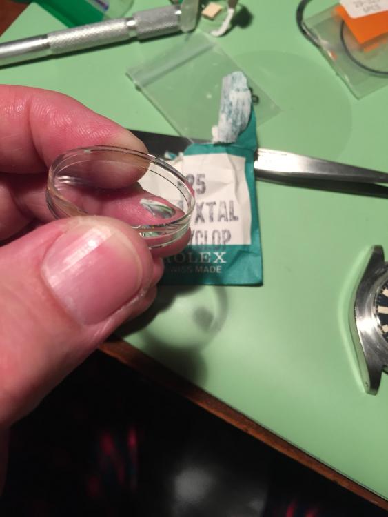
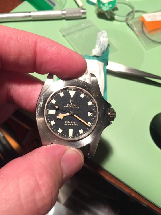
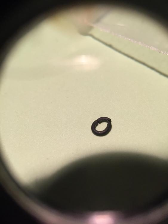
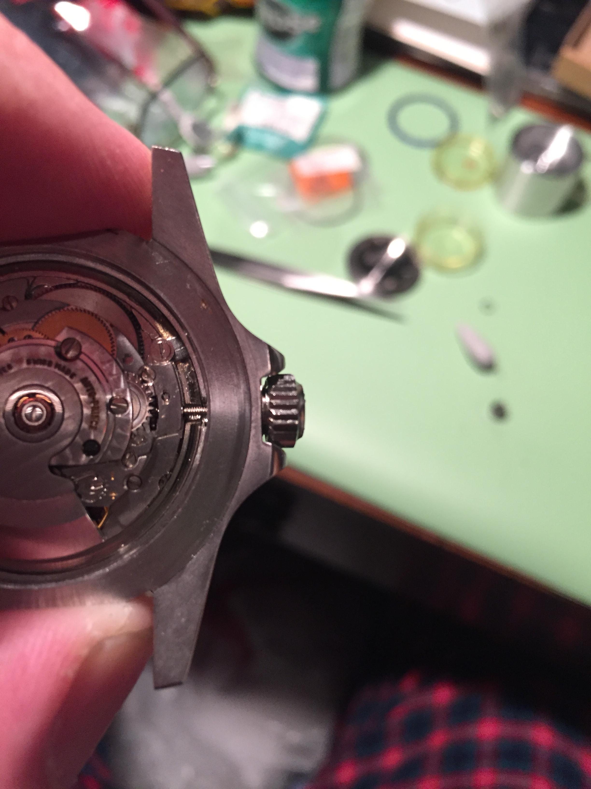
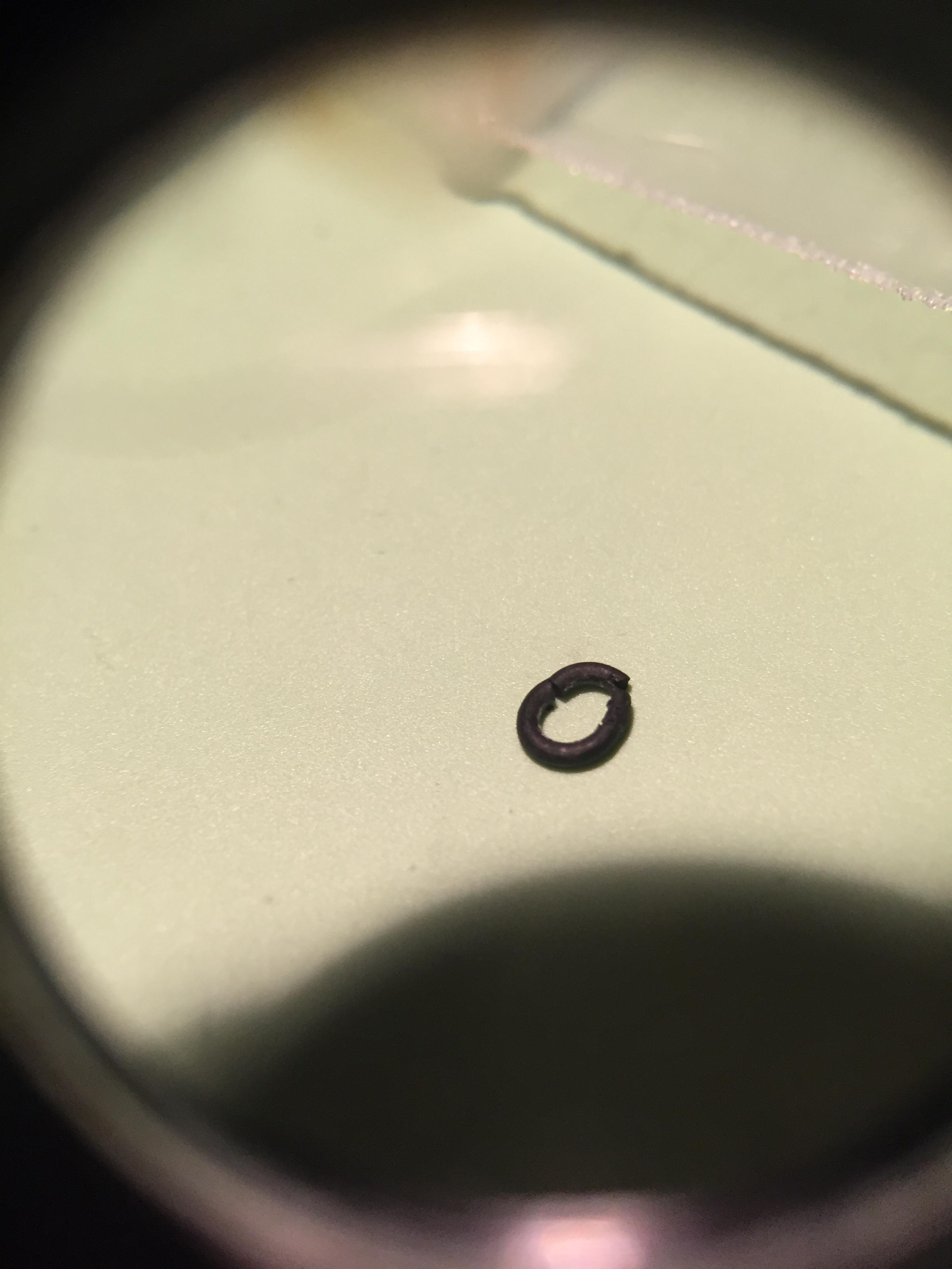
Finally tonight I (nearly) finished recasing my blue snowflake. I have been collecting parts for years and the case is quite elusive. I’ve been using a (decent) aftermarket case and a few months ago found a nice 1976 Case. I’ve been itching to get this together ever since! we start with disassembly of the current watch. It served well and I always enjoy wearing this watch. At least as much as my 1680. Take the back off, pull the stem and then the movement. We must be VERY CAREFUL as these original blue dials are extremely delicate. The blue paint “rots” on these. It gets lumpy and then flakes off. Once the movement is out, I also want to replace the seconds hand, which has a short tail. I have a genuine one but it needs to be broached slightly. This is an aftermarket one of near perfect shape. Lume color was adjusted by Dunkin Donuts coffee. Next we case it up. Again, very careful to protect the dial. Set the dial in the counterbore - It’s small, but it’s there. And very important to set the dial straight in it. That paint can chip on any dial messing this part up and these old blue ones are particularly vulnerable. Then the movement ring goes in. It is notched for the stem, so we need to line that up well. I sight through the crown tube to be sure all is aligned and centered. Start the tab opposite the crown then the crown side. Just catch the screw threads because it always needs further tweaking. Check the dial is seated perfectly... Once I’m happy I tighten it evenly, back and forth. New old stock 702 crown. One word of caution here- the o-ring was petrified even though sealed in the little blister since 1973 or so. If you work on this vintage stuff, be sure you have fresh gaskets. Two o rings go inside the tube, and one on the crown. The crown one seals on the end face of the tube and the two in the tube seal on the crown stem OD. Three seal points- the “triplock “ crown. Stem length was perfect and it took some effort to screw the stem in so I left it dry. When they are loose, I’ll use purple low strength loctite on them. I avoid it when I can because it can make life miserable and 2784 stems are not easy (or cheap) to find. Now we finally set the crystal. A lot of guys set it earlier, getting the case “ready” ahead as it is a bit more “brute” than other watch work. The reason I wait is to set the crystal in perfect alignment with the date window. I use the loupe and ensure the top and bottom edge of the cyclops are parallel to the date window. Not a big deal but when it’s off, it’s annoying to me. I keep a scrap crystal on the case so I don’t ham fist the hand stack... Now the crystal retainer- it slides over the crystal and is pressed firm and flush to the top of the mid Case. Mine is 99% there now. A crystal press doesn’t have the “nut” to do it so I use a small arbor press out in the garage. It was for pressing frets into fingerboards when I was building guitars. The drill press works fine too, if it’s a floor model. Well that’s where we’re at now. Tomorrow I’ll press the retainer fully home and then deal with the bezel. That may end up another complete thread...
 1 point
 -
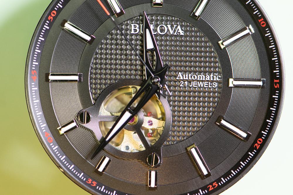
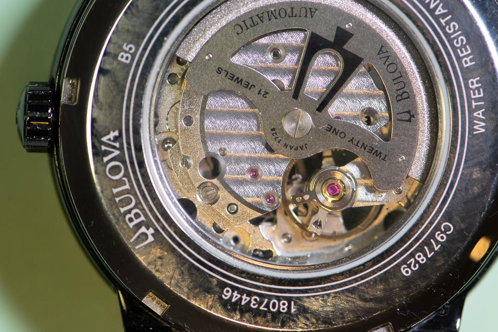
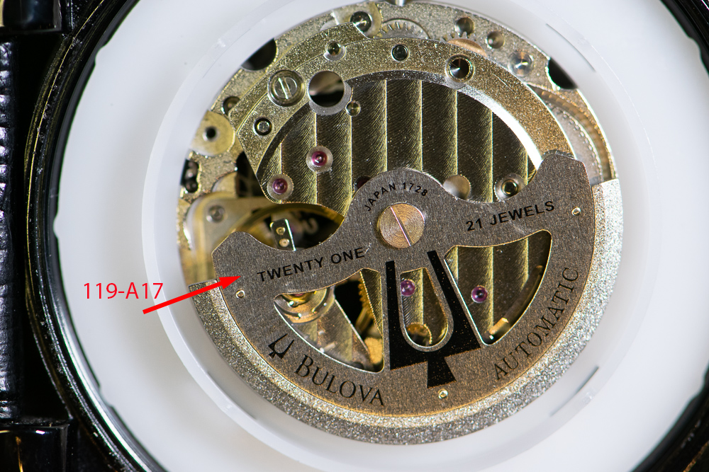
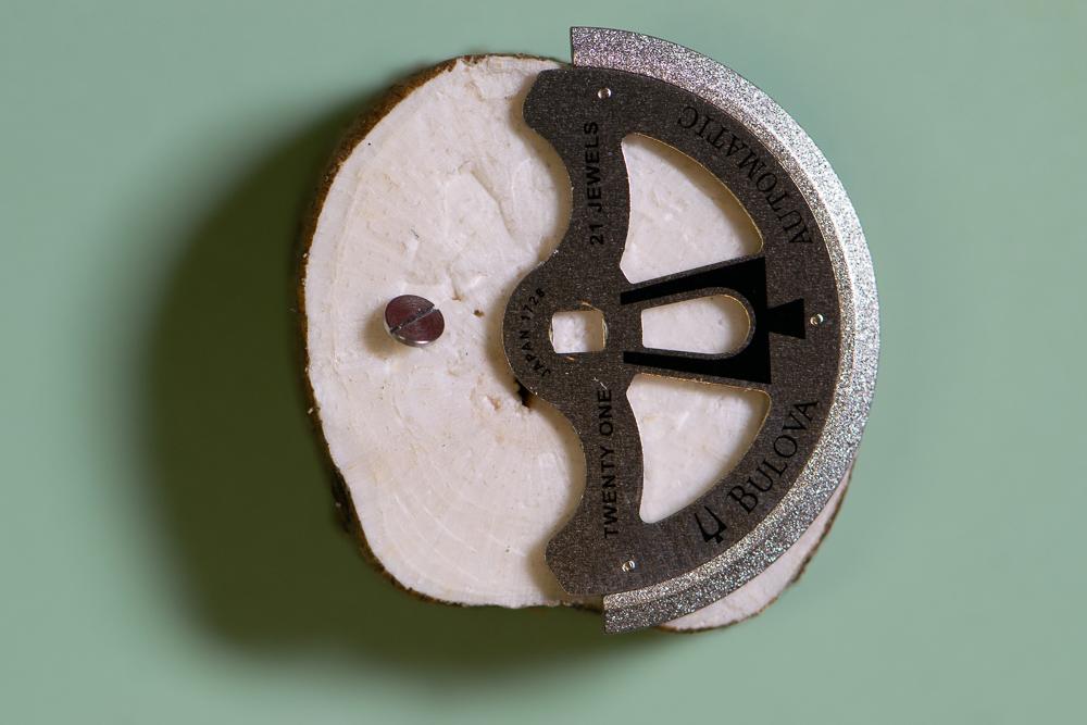
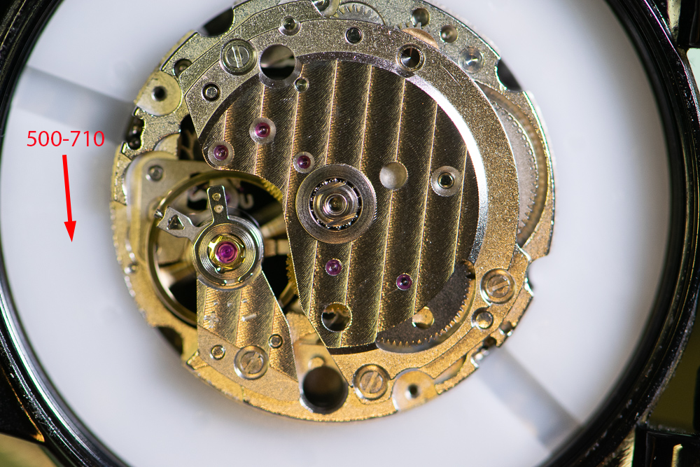
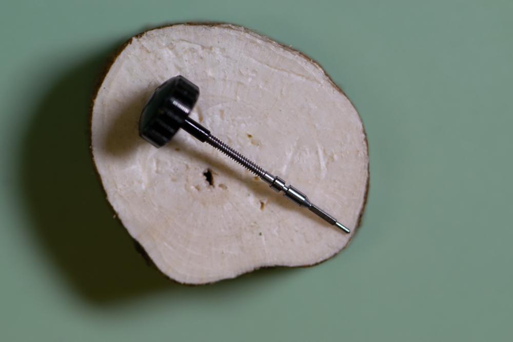
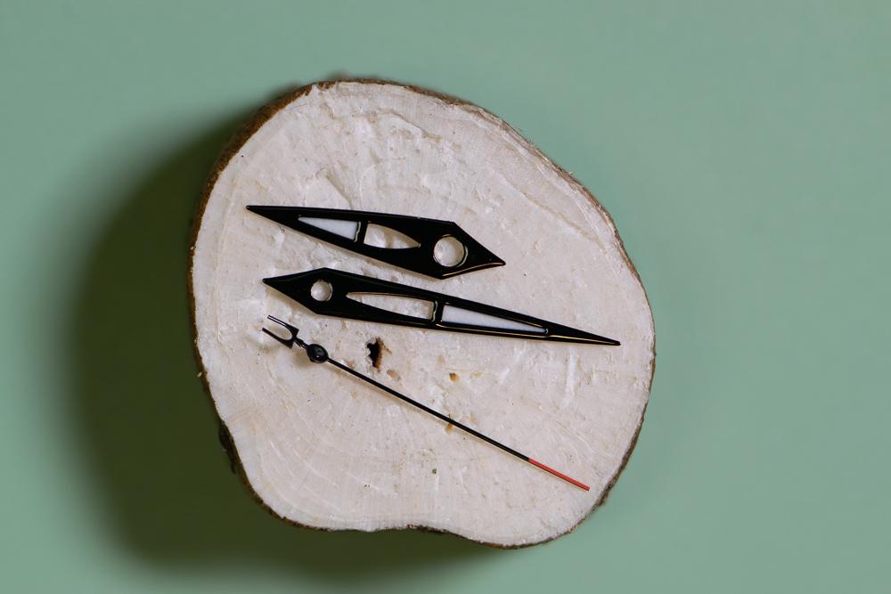
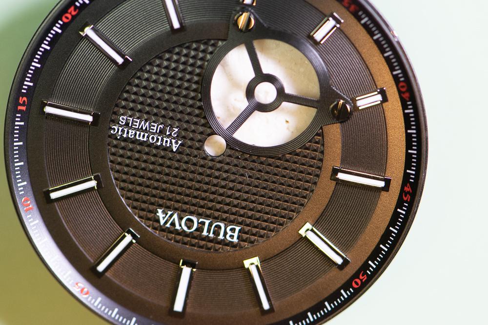
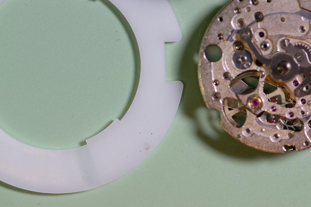
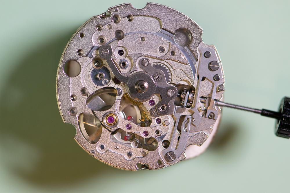
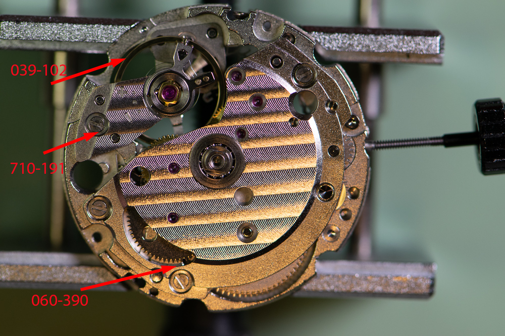
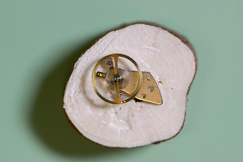
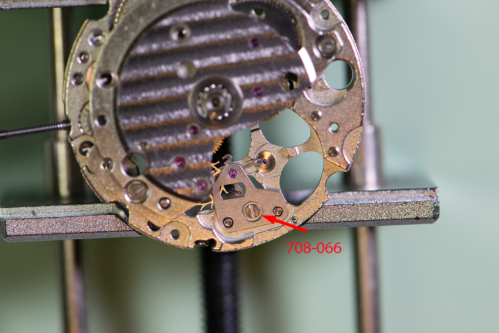
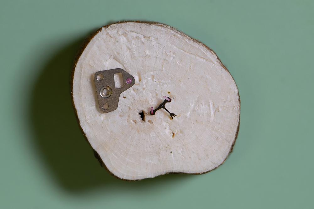
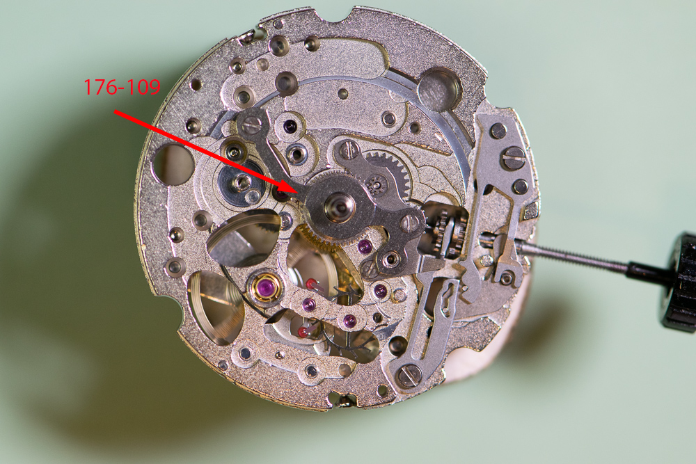
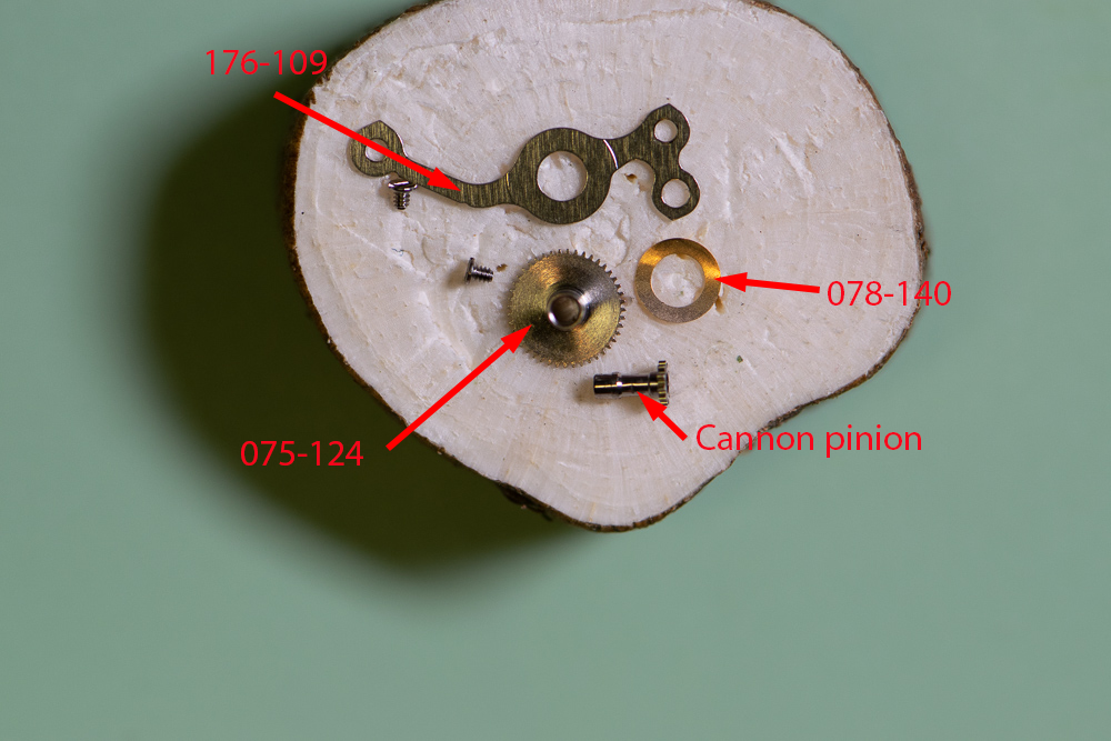
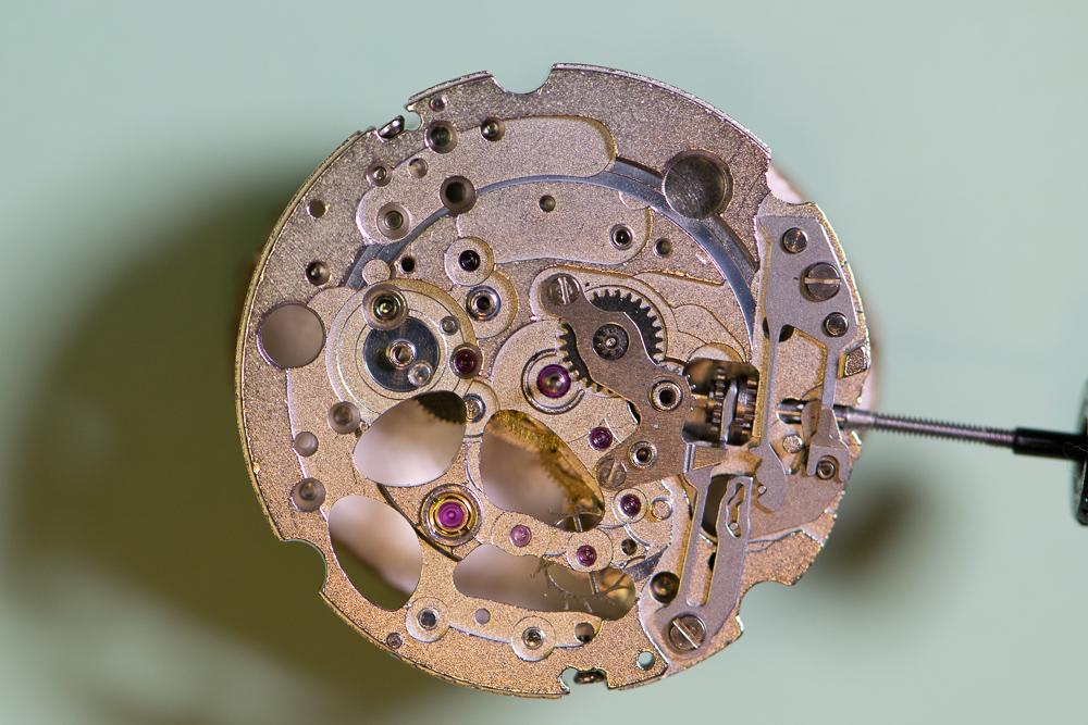
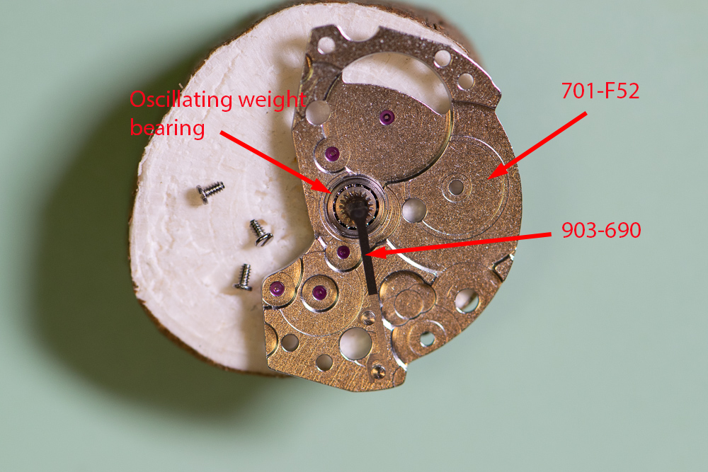
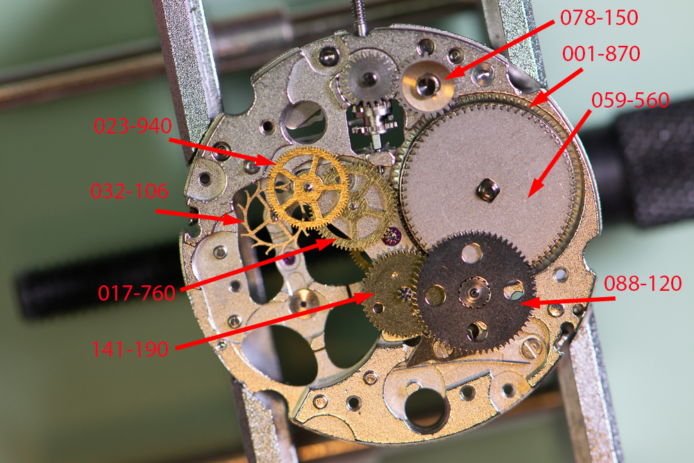
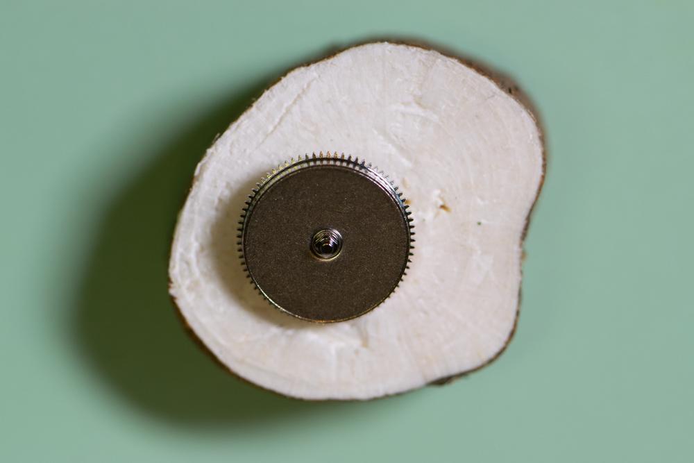
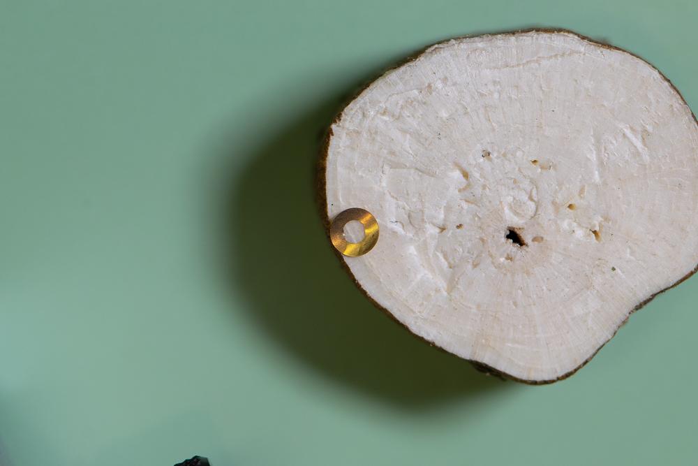
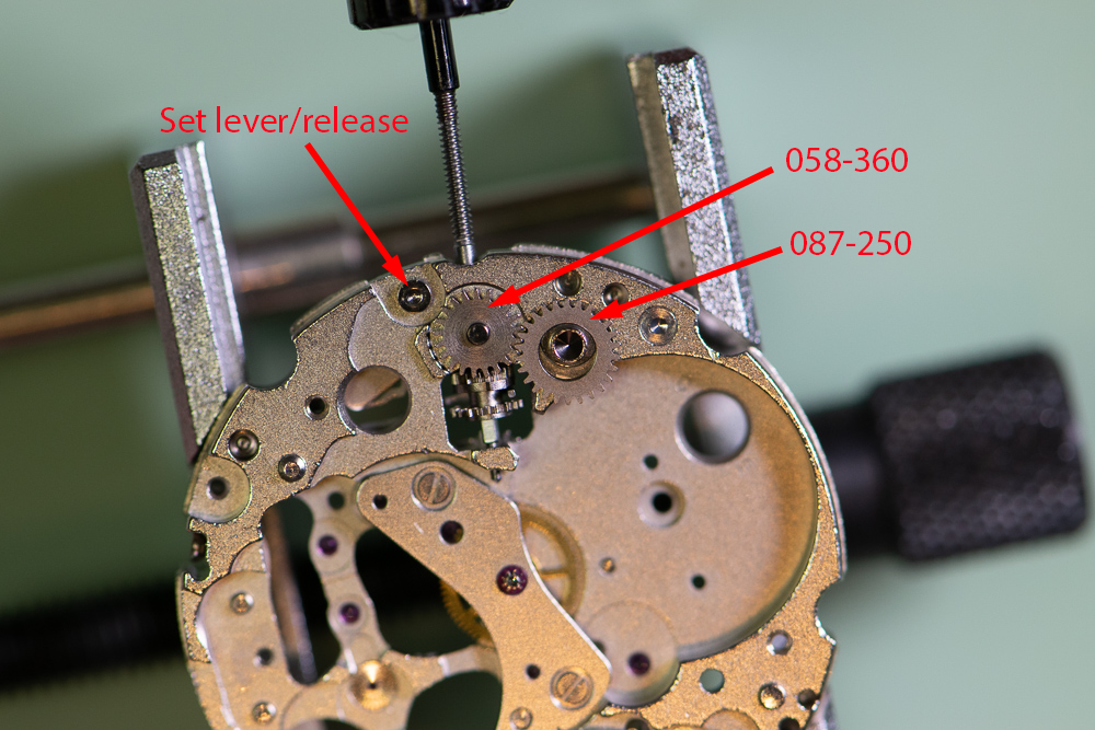
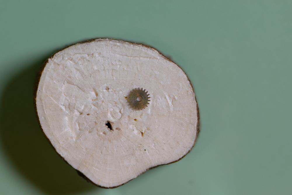
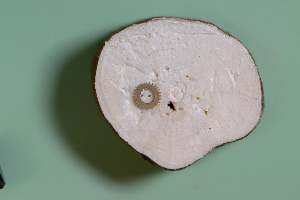
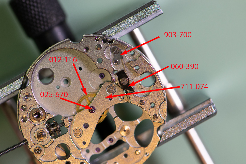
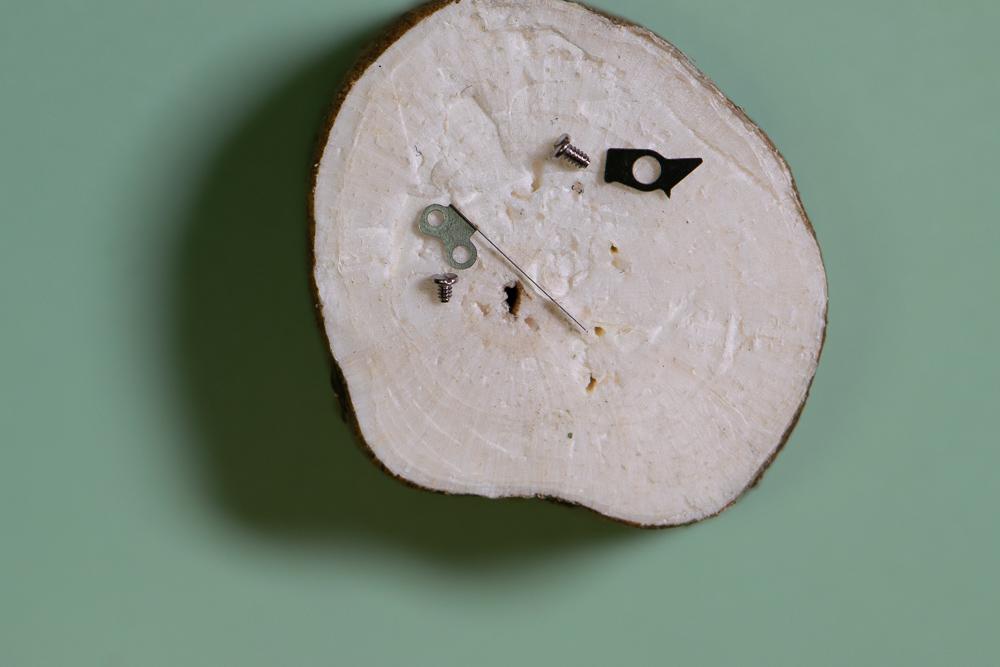
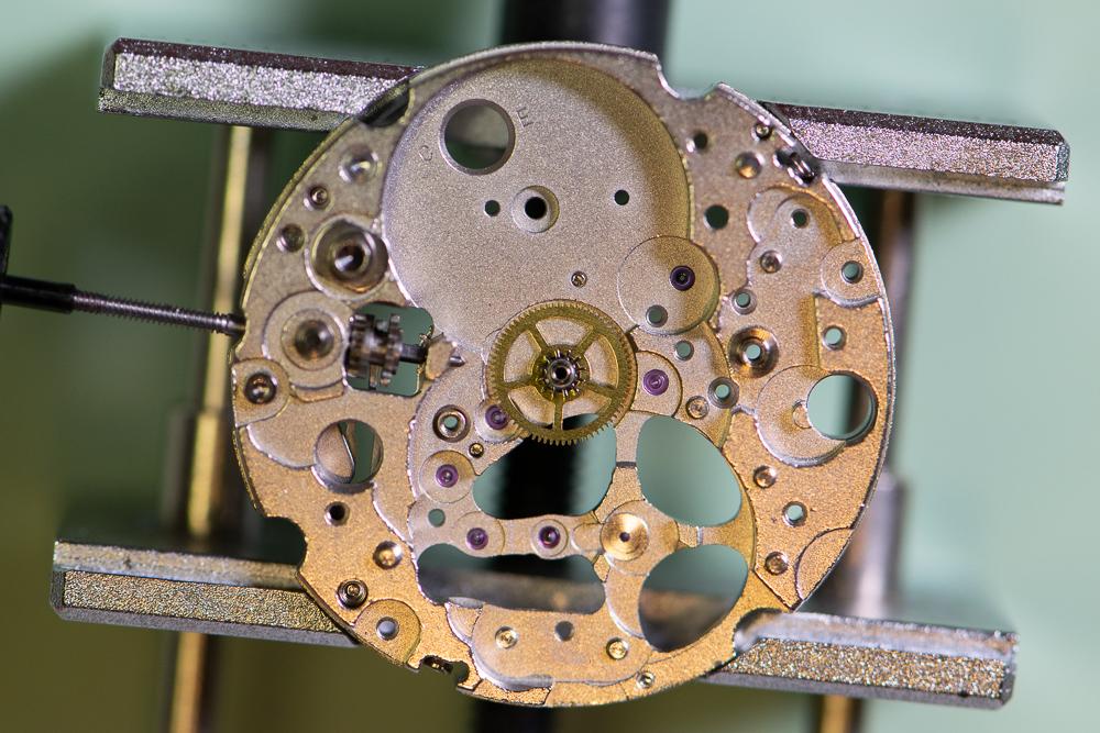
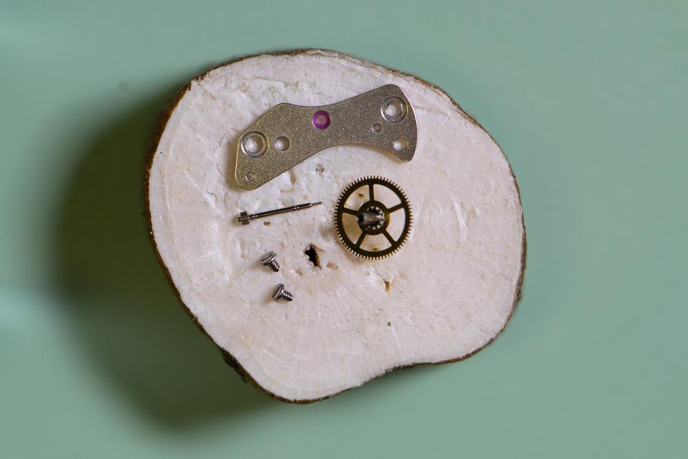
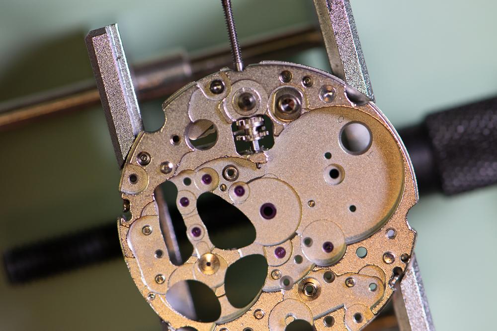
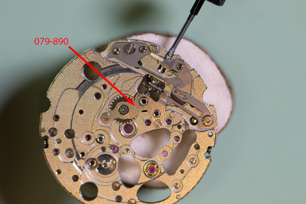
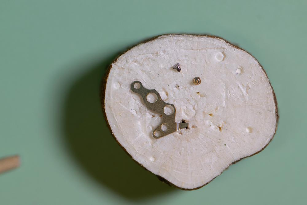
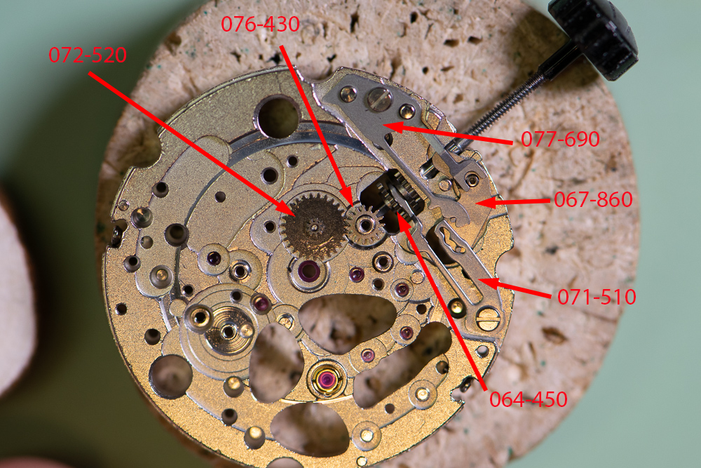
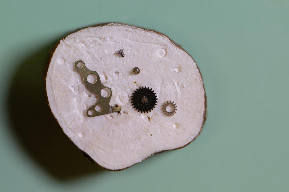
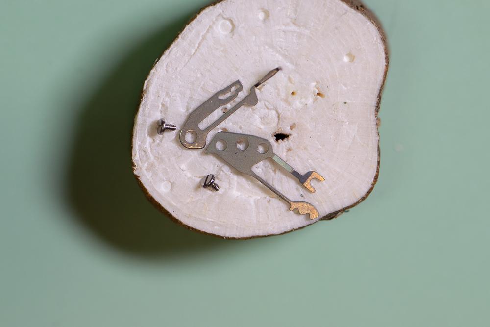
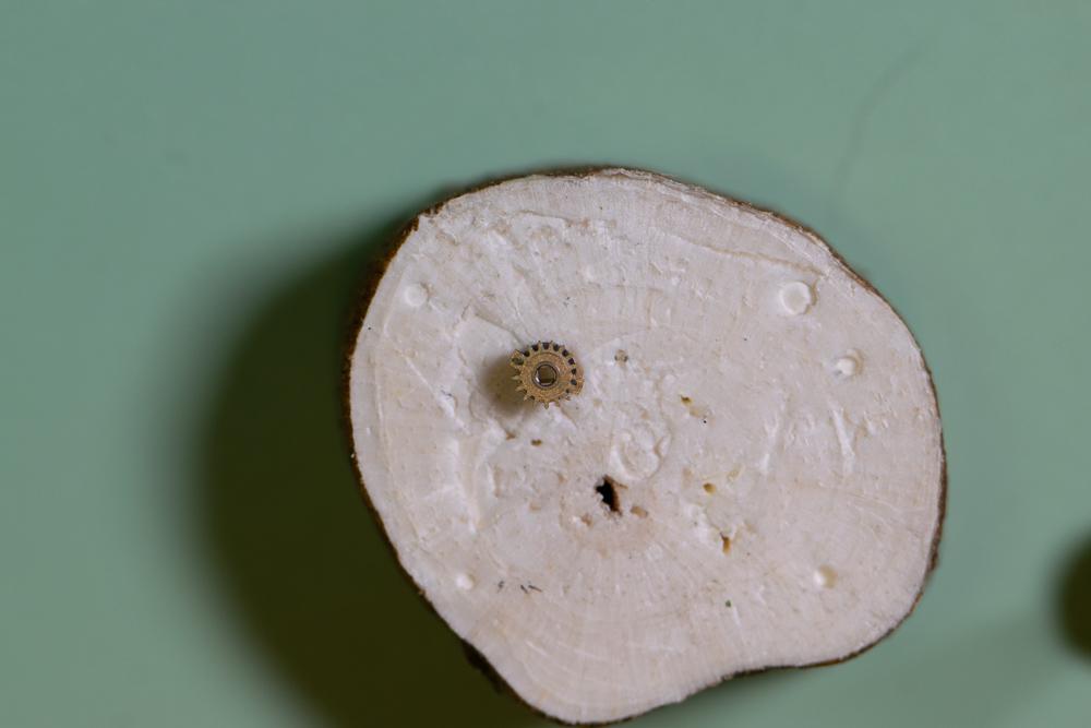
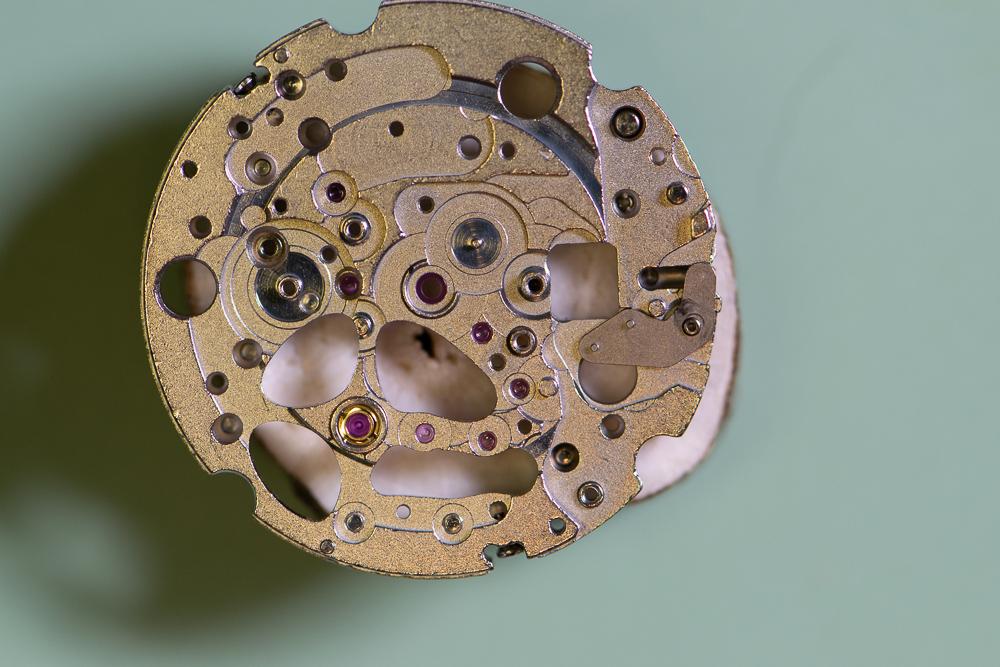
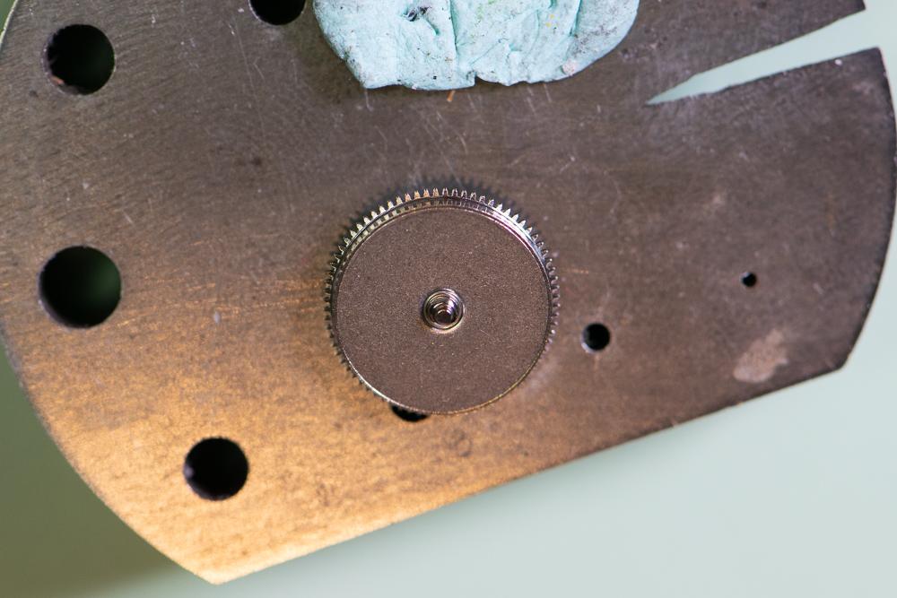
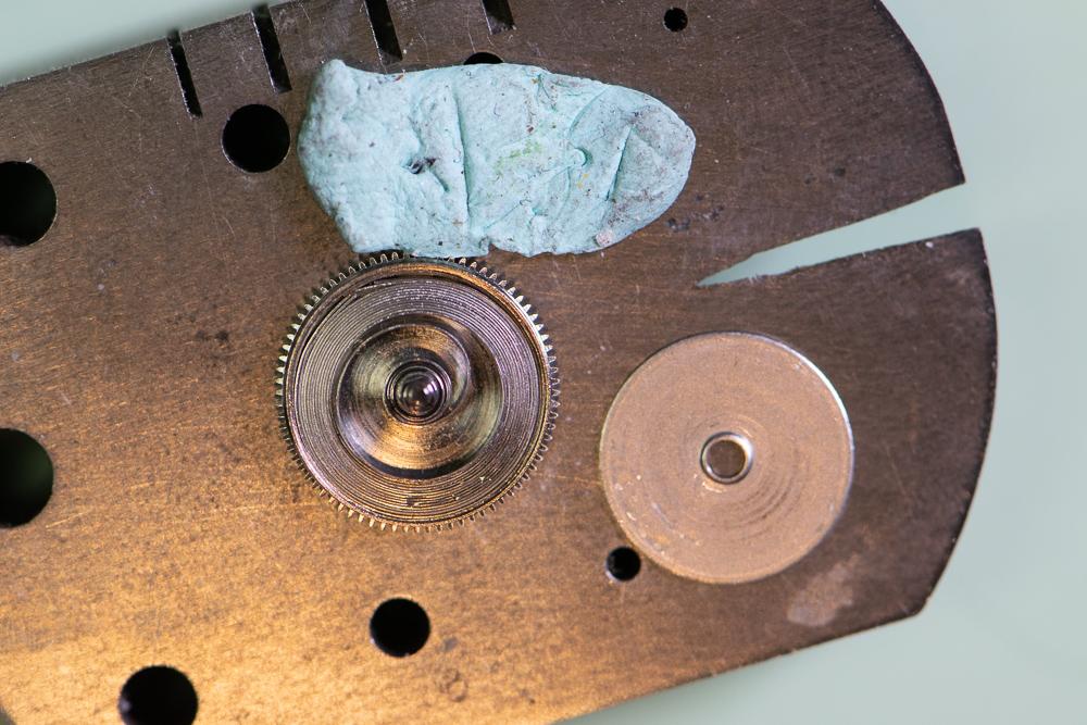
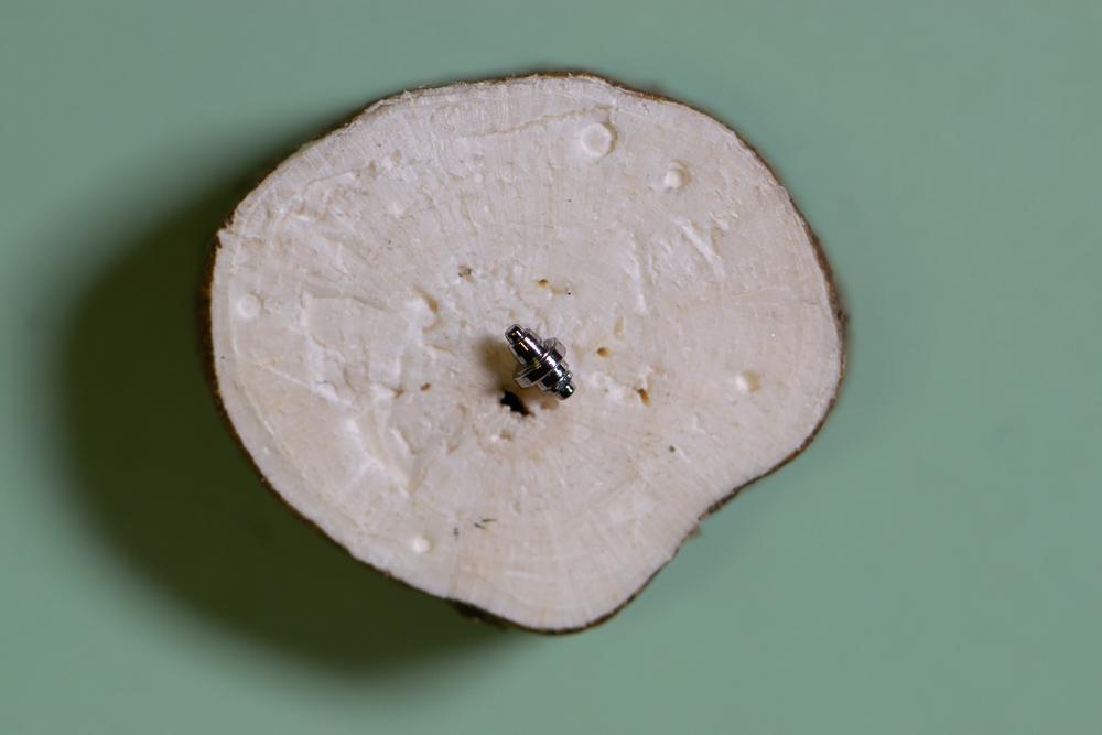
This is a more detailed version of my previous picture-only post for this watch. This Bulova 21-jewel automatic was given to me by a colleague for repair. It was running extremely fast – gaining about 15 minutes per hour. The movement is a Citizen/Miyota 82S0 skeleton. Looking through the clear back it was obvious that the balance amplitude was extremely low. First step was to simply demagnetize the watch to see if that did the trick as it sometimes does. No dice. I then removed the balance and pallets and put a small amount of wind onto the mainspring. The train spun up but as power wore off the escape wheel stopped, then started again several times. It was a very sloppy action. Nothing obvious in terms of loose or cracked jewels or excessive side or end shake that I could see. I decided to disassemble the movement and give it a full servicing. Here is how I disassembled the movement. Where I can I will list the Miyota part number for reference. You can find the parts list here: http://miyotamovement.com/parts_search.php?open=82S0 Figure 1 shows the face of the watch after removing from the case. Note the exposed balance at the 7 o’clock position. Figure 1 – Face Figure 2 shows the clear case back prior to removing the movement. Figure 2 – Case back The first step in disassembly is to remove the Oscillating weight (119-A17. Note that the weight is secured to a bearing that is pressed into the main plate. Unlike many Swiss movements, the screw securing the weight rotates with the weight itself. I used a peg wood stick to prevent the weight from rotating while unscrewing the fastener. Figure 3 shows the weight prior to removal. Figure 4 shows the oscillating weight after removal. Figure 3 – Preparing to remove the oscillating weight Figure 4 – Oscillating weight Figure 5 shows the movement after removing the oscillating weight. The plastic movement holder (500-710) is also visible. This will be removed after dealing with the hands and dial. I also removed the winding stem (figure 6) by pressing in on the setting lever and gently pulling the stem. The location for pressing on the setting lever was clipped from the pic, but it’s a standard setup. Figure 5 – Plastic movement holder Figure 6 – Winding stem After removing the stem, the movement was removed from the case. The stem was then reinstalled to facilitate power let-down, etc. With the oscillating weight removed, it’s a simple matter to lay the movement down dial-up on a piece of pith wood and remove the hands (Figure 7). The dial retaining screws on the side of the movement are loosened (not removed) and the dial is gently coaxed away from the movement by inserting a thin screwdriver blade. Figure 8 shows the dial after removal. Figure 7 – Hands Figure 8 – The Dial The movement holder shown in figure 5 is now lifted off. It is shown in figure 9 next to the movement. Figure 9 – Movement holder ring Figure 10 shows the dial side of the movement. Figure 10 – Dial side The movement is then flipped dial down and loaded into a movement holder for disassembly. The balance (039-102) is removed along with the balance bridge (710-191) as shown in figure 11. Figure 11 – Preparing to remove balance The balance complete is shown after removal in figure 12. Figure 12 – The balance complete Important: Before removing the pallets I need to remove all the power from the mainspring. I do this in the standard way – by applying a bit of winding pressure on the crown while pulling the click (060-390 in figure 11) out of the way with a bit of peg wood and allowing the stem to unwind in a slow/controlled manner. Figure 13 – About to remove pallets With the power let down I can now remove the pallet bridge (708-066) and pallets. Figure 13 shows the bridge prior to removal. The pallets and bridge are shown in figure 14. Figure 14 – Pallets and pallet bridge I probably should have removed the motion work prior to starting in on the balance – not sure why I didn’t. Regardless, we need to flip the movement back so I can remove the motion work from the dial side. The hour wheel is held in place by the hour wheel spring (176-109). Remove the 2 retaining screws and then lift off the spring. The spring is shown prior to removal in figure 15. Figure 15 – Hour wheel spring prior to removal Once the hour wheel spring is out of the way I can remove the dial washer (078-140), the hour wheel (075-124) and finally the cannon pinion (using your favorite cannon pinion removal tool). These parts are shown after removal in figure 16. Figure 16 – Hour wheel spring, hour wheel, dial washer and cannon pinion Figure 17 shows the movement after removal of the motion work. It’s now time to flip the movement back over and start in on the gear train. Figure 17 – After removing the motion work I remove the three screws securing the barrel and train wheel bridge (701-F52) and carefully remove it. Figure 18 shows the underside of the bridge. Note that the seconds pinion friction spring (903-690) was left in place. I didn’t see the point in removing it. You can also see the oscillating weight bearing that is press fit into the bridge. I didn’t mess with this either! Figure 18 – Barrel and train wheel bridge and seconds pinion friction spring Figure 19 shows the detail after removing the barrel and train wheel bridge. First, I remove the reduction gear (088-120) and reversing wheel (141-190). These components are part of the automatic winding mechanism. They are shown in figures 20 and 21 after removal. I make note that the reversing wheel should be installed with the brass side up. Figure 19 – After removing barrel and train wheel bridge Figure 20 – Reduction gear Figure 21 – Reversing wheel Next, remove the third wheel (017-760), fourth wheel (023-940) and escape wheel (032-106). These are shown in figure 22. Figure 22 – From left to right – escape wheel, fourth wheel and third wheel Next, I remove the ratchet wheel (059-560) and the barrel complete (001-870), which sits directly underneath the ratchet wheel. Th.ese components are shown in figures 23 and 24. Figure 23 – Ratchet wheel Figure 24 – Barrel complete Looking back at figure 19, you can see a spring, very similar to a dial washer. This part is called the ratchet sliding wheel spring (078-150). Simply lift it off (figure 25). Figure 25 – Ratchet sliding wheel spring With the spring out of the way I can now see the ratchet sliding wheel (087-250). I remove this part along with the crown wheel (058-360). Figure 26 shows these parts. Ah – finally a picture that shows the setting lever release button I mentioned earlier! Pressing here allows the stem to be removed. I will leave the stem in place for now. Will get to it shortly. Figures 27 and 28 show the parts just removed. Figure 26 – Crown wheel and ratchet sliding wheel Figure 27 – Crown wheel Figure 28 – Ratchet sliding wheel Figure 29 shows the click (060-390) and click spring (903-700), the center wheel cock (711-074), center wheel (012-116) and center seconds pinion (025-670). Technically I believe the center wheel cock should be named the center wheel bridge since it’s secured by more than one screw, but I’ll leave that open for debate. Tension on the center seconds pinion is provided by the friction spring we saw back in figure 18. Figure 29 – Click and spring, center wheel and cock, center seconds pinion Figure 30 depicts the click and click spring after removal. Figure 30 – Click and click spring Figure 31 shows the center wheel in place after the center wheel cock has been removed. Figure 31 – After removal of the center wheel cock Figure 32 depicts these parts after removal. Figure 32 – Center wheel cock, center wheel and center seconds pinion The train side of the movement is now fully stripped. This is shown nicely in figure 33. Time to flip it over and finish off the dial side. Figure 33 – Finished with the train side Figure 34 shows the current state of the dial side of the movement. To get started I remove the minute train cover (079-890). Figure 35 shows this component after removal. Figure 34 – Dial side Figure 35 – Minute train cover I can now remove the keyless work. The components are shown in figure 36. The minute wheel (072-520) and setting wheel (076-430) are removed first. These components are shown in figure 37 along with the minute train cover. Figure 36 – Keyless work components Figure 37 – Minute and setting wheel Referring back to figure 36, the next components to remove are the yoke (071-510) and setting lever spring (077-690). The stem can now be removed and then the clutch (064-450) is free to remove. The setting lever (067-860) was not removed as it’s press button is staked (spread). No sense disturbing this. Figure 38 shows the yoke and setting lever spring after removal. The clutch is shown in figure 39. Figure 38 – Yoke (left) and setting lever spring Figure 39 - Clutch Finally, the main plate is fully stripped. The dial side is shown in figure 40. Figure 40 – Main plate – dial side We can now deal with the barrel assembly (figure 41). Figure 41 – Mainspring barrel complete Using the steel anvil for support, gently press down on the gear teeth to pop the barrel cover off (figure 42). Figure 42 – Barrel cover removed Carefully remove the barrel arbor (figure 43). Figure 43 – Barrel arbor Unwind the mainspring from the barrel (figure 44). Figure 44 – Barrel with spring removed This completes the disassembly of the movement. My next step will be to clean it in the ultrasonic. Will post the reassembly as a new thread.
 1 point
 -
What a brilliant easy to follow strip down loved it Sent from my iPad using Tapatalk1 point
-
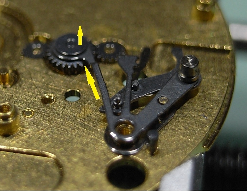
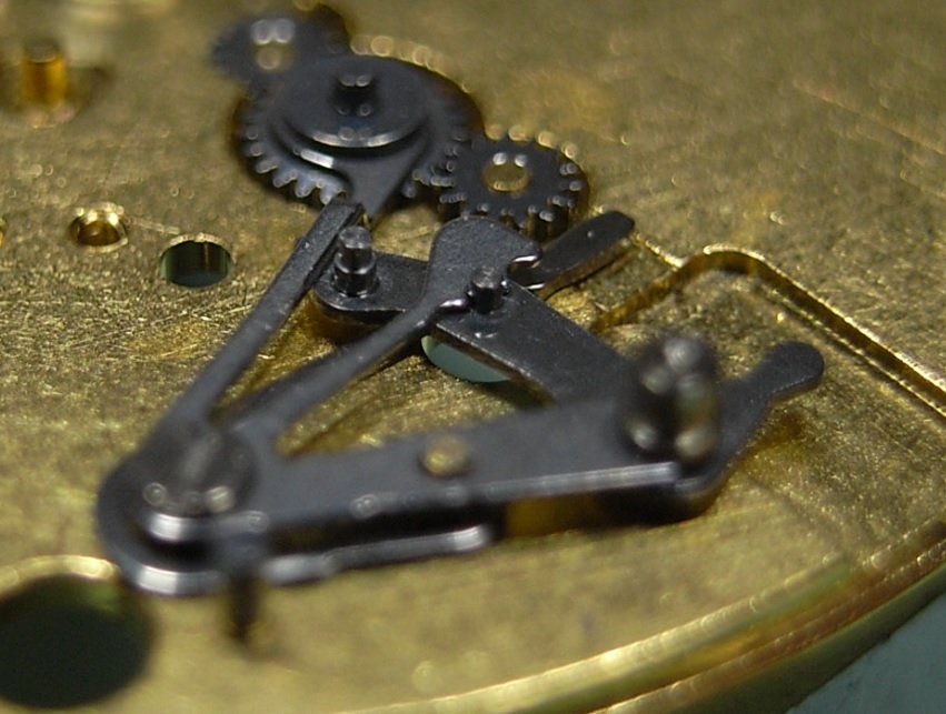
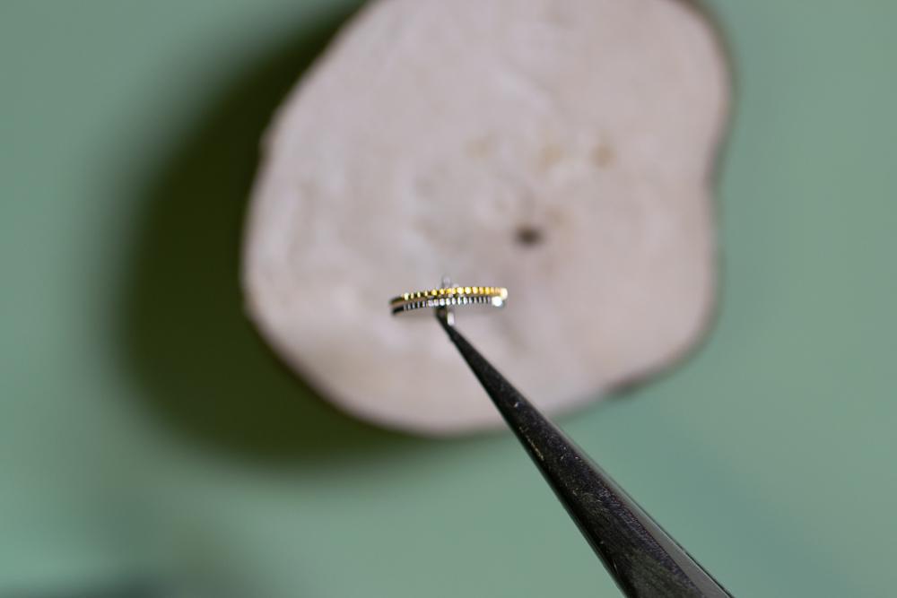
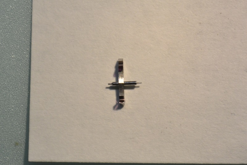
The roller pinches the hairspring end against a groove in the smaller rod. That rod can be turned with the upper knob, which feeds the hairspring through the groove and roller. Very handy as you aren't constantly manipulating the spring with tweezers, and the same design was used by Greiner on their old stroboscopic (and current) vibrating machines. It can be sketchy to use with very small hairsprings like under 7 ligne.1 point
-
Thanks, I do like it myself and works great
 1 point
 -
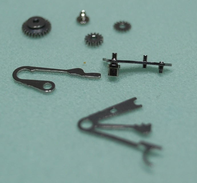
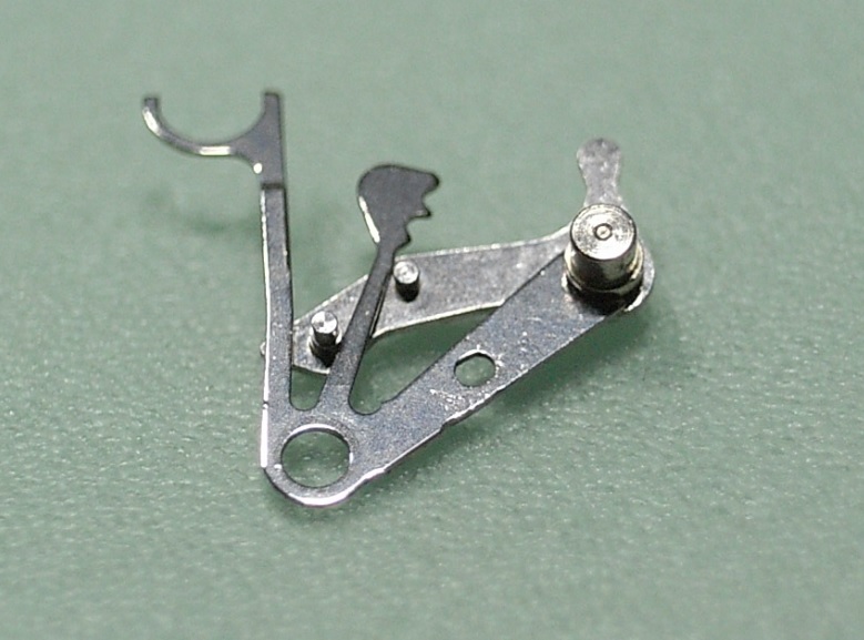
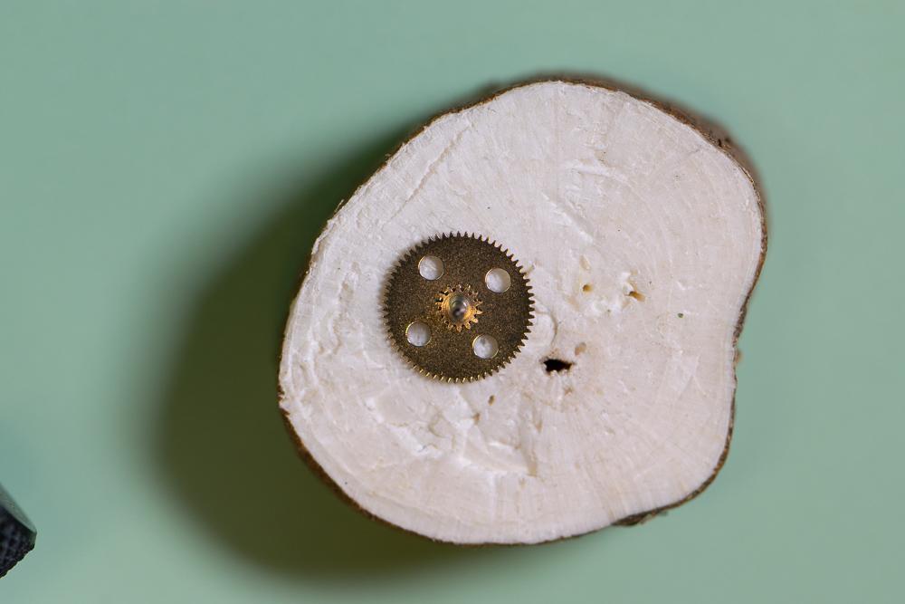
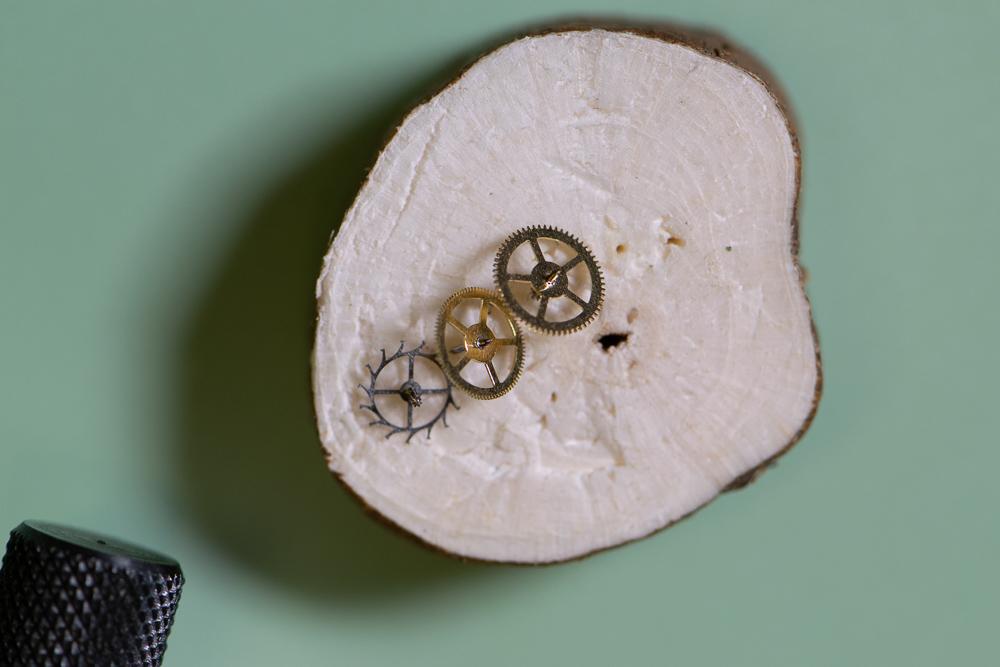
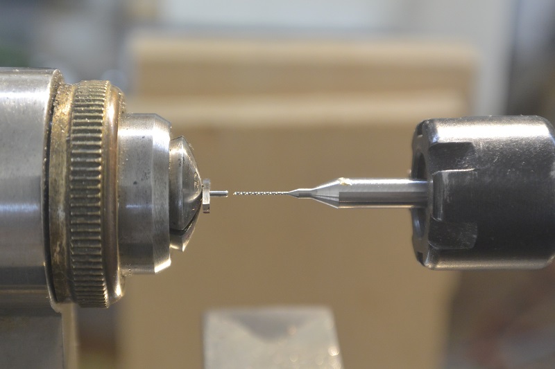
Broken pallet arbor pivot ? You have two options : repivoting or turn a new arbor. I don't have the stuff and the skill to turn between centers, so i tried repivoting : 1. True the broken face 2. Mark the center (use a x20 eyeglass ) 3. Drill (0.3mm) with a carbide drill on the lathe , depth around 2 to 3 times the diameter of the drill 4. Turn the plug, make some test and try until you find the right diameter (you must be 1/100 larger than the hole). Add a notch at approximately the dimension of the pivot plus the depth of the hole 5. Set the plug at low speed until the notch break (don't forget to add some Loctite 603) 6. Secure the plug with a light hammer 7. Finish the pivot (0.18mm) Drilling on the lathe, i use a ER11 collet holder in the tailstock from GG tools, go very very slowly. Finished pallet, unfortunately i broke a stone in the process and had to replace it, i believe it's a shock with the tool rest when finishing the pivot , so be very careful !
 1 point
 -
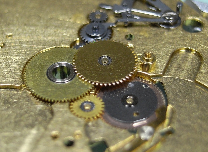
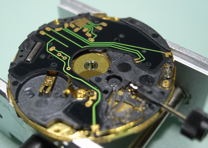
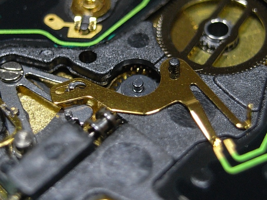
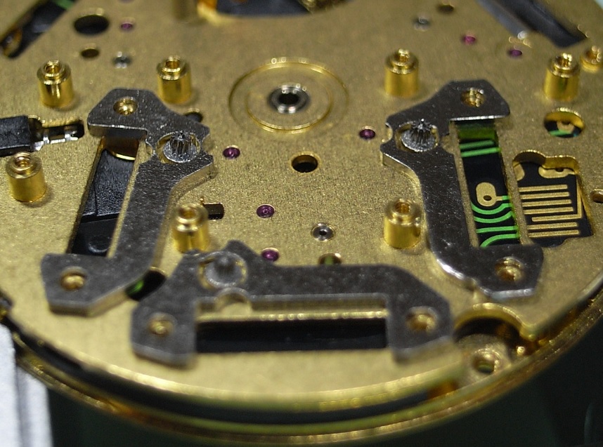
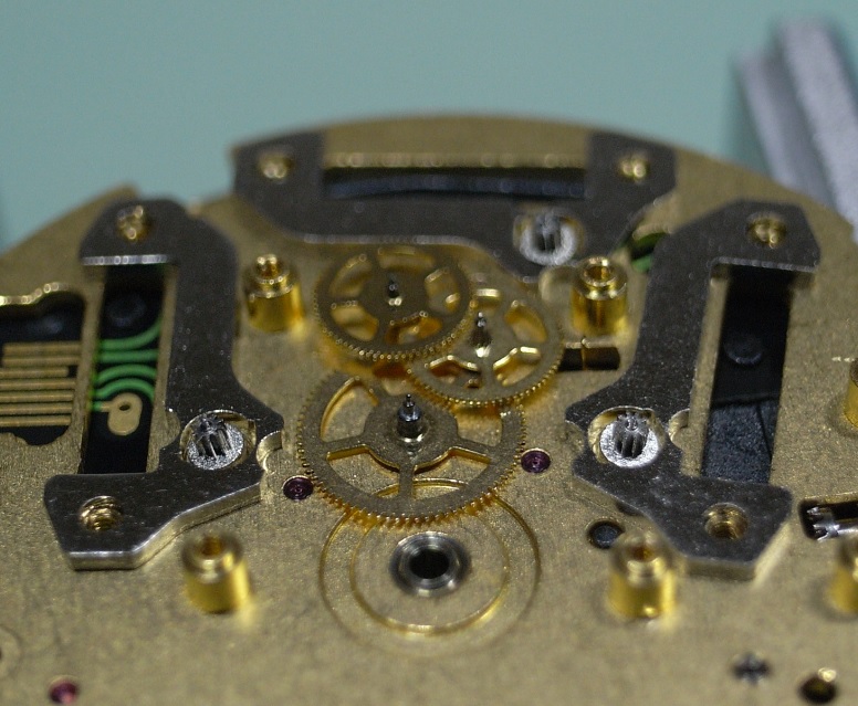
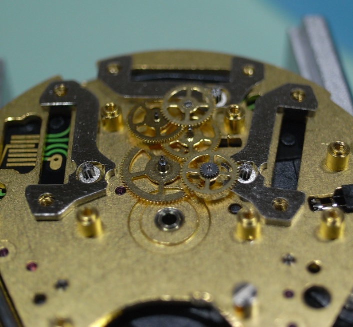
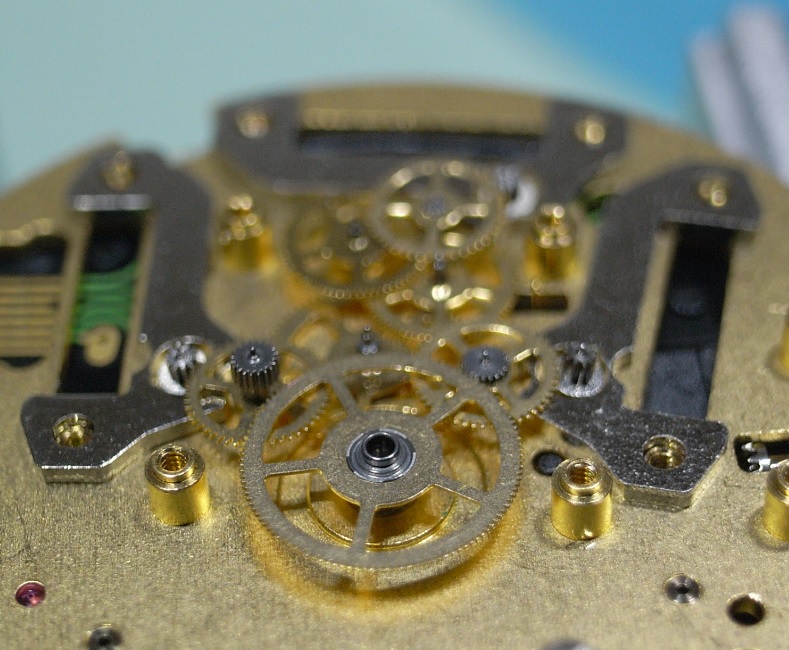
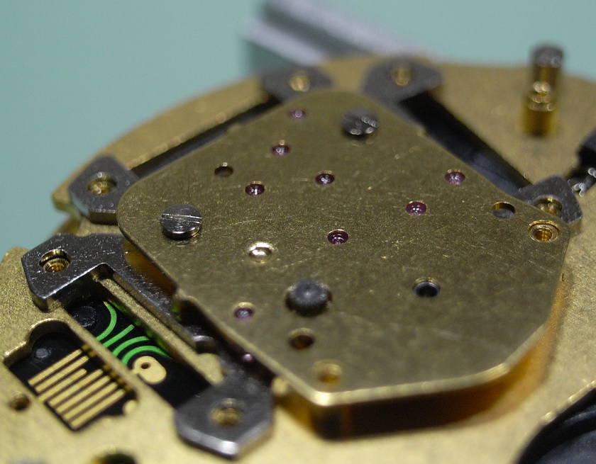
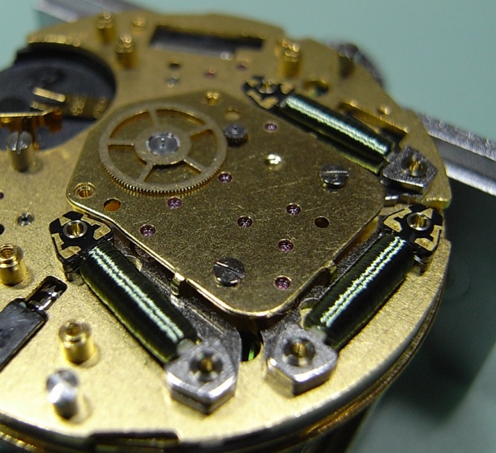
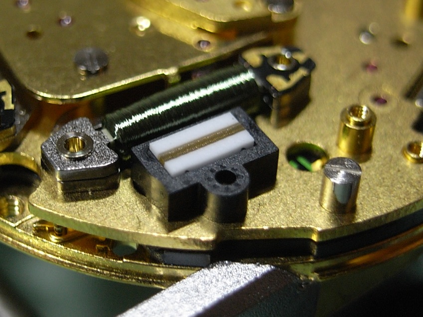
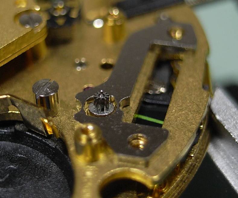
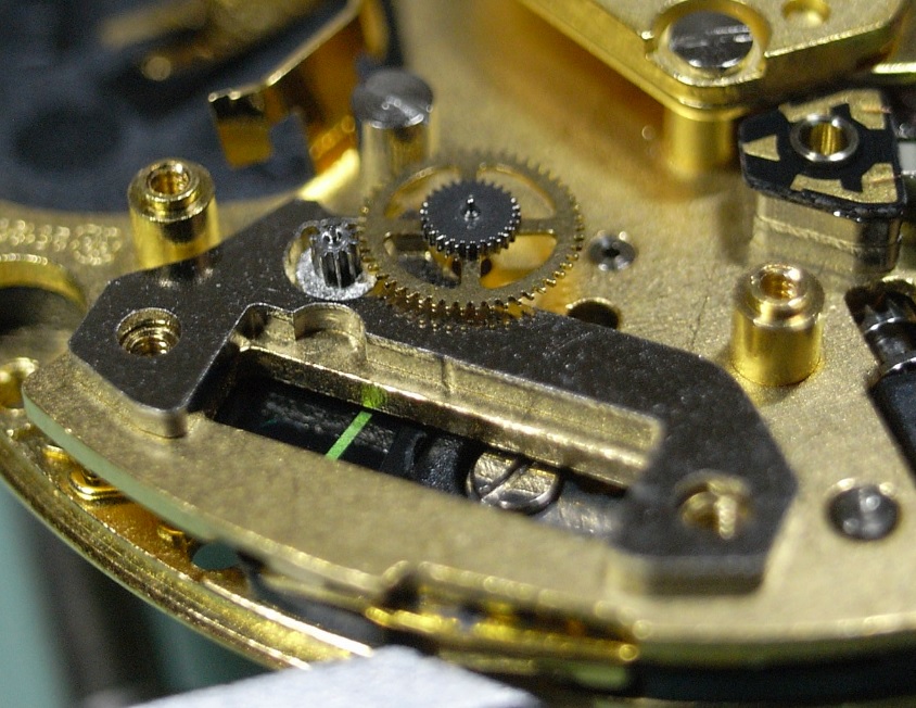
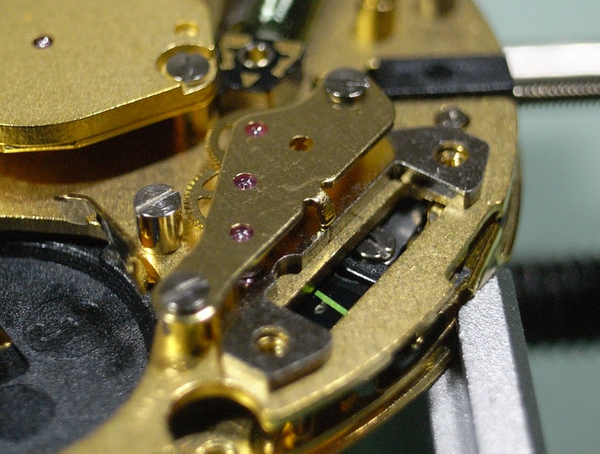
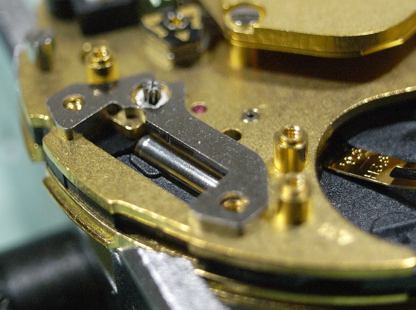
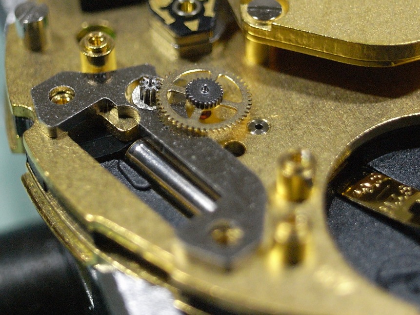
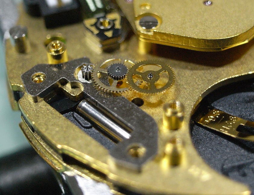
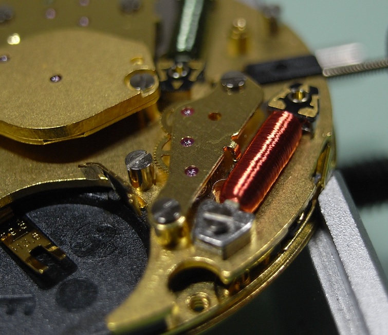
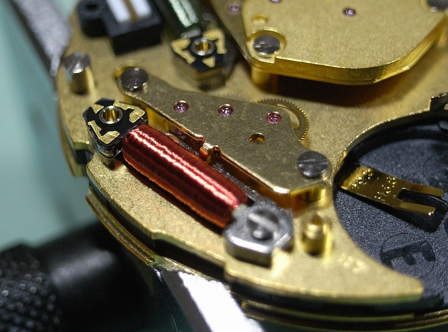
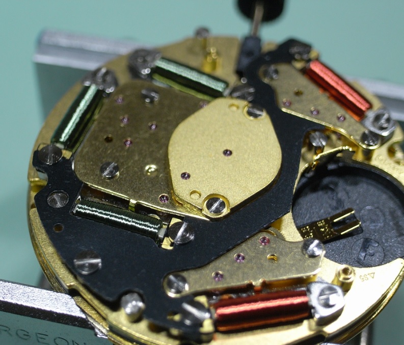
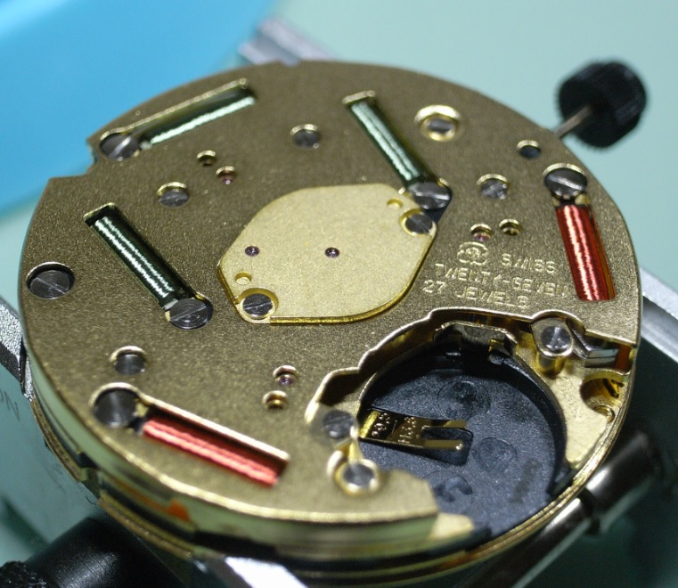
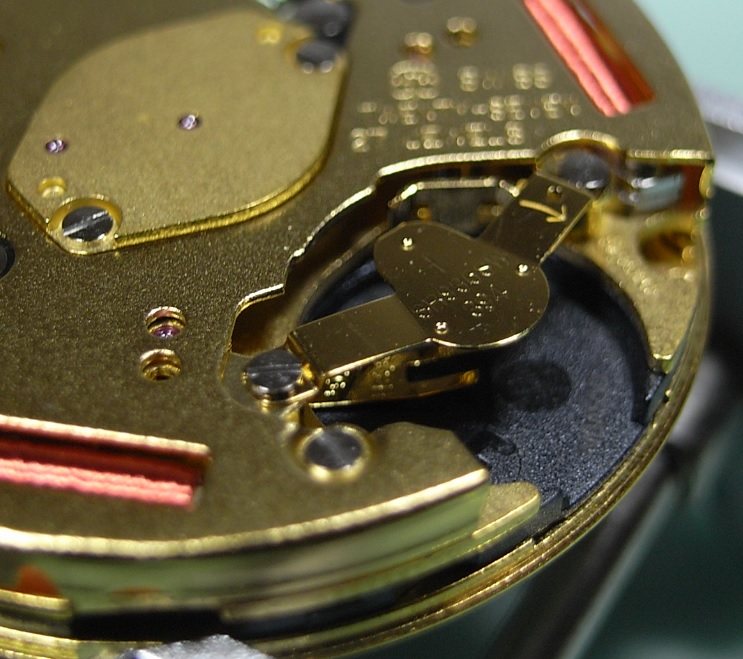
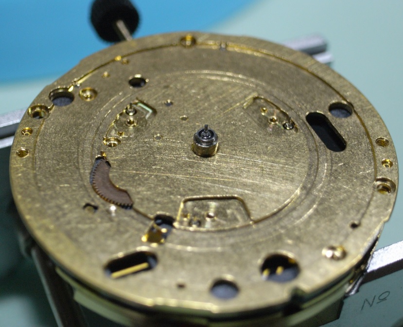
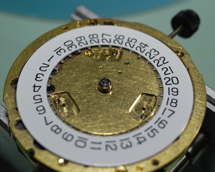
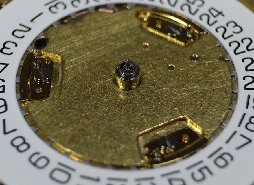
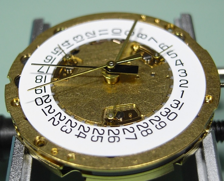
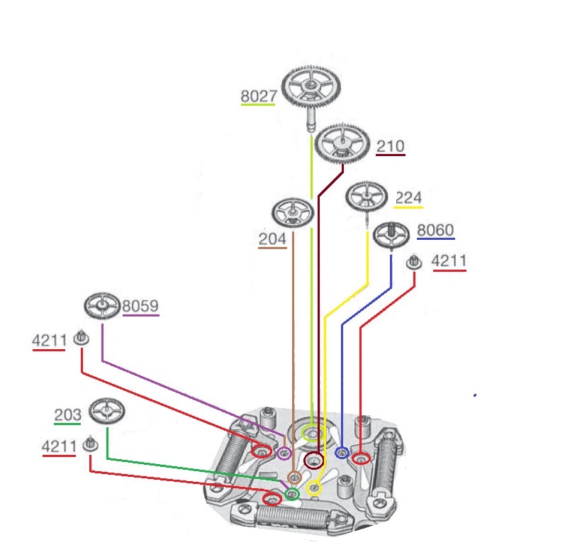
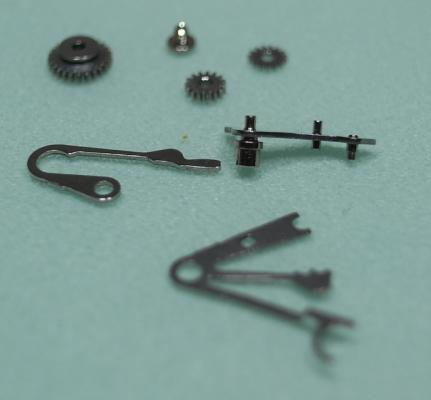
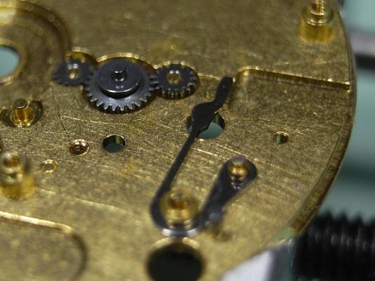
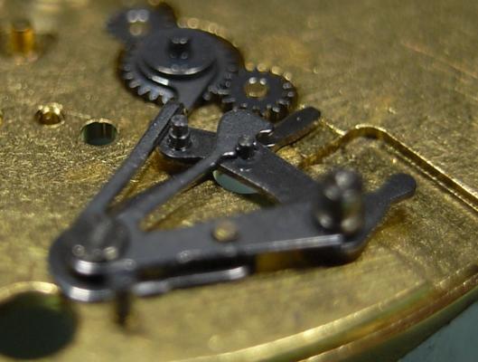
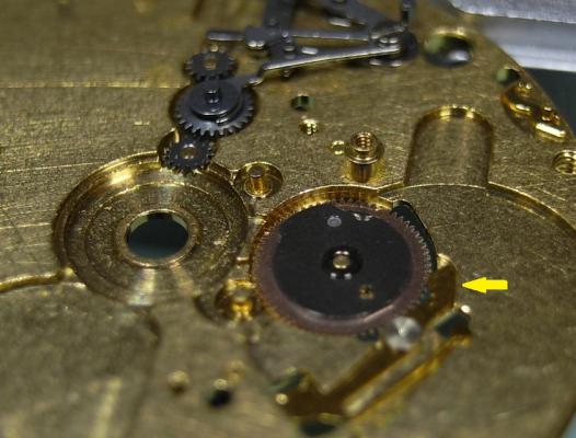
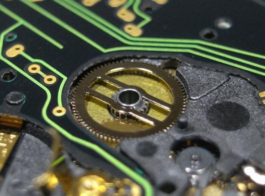
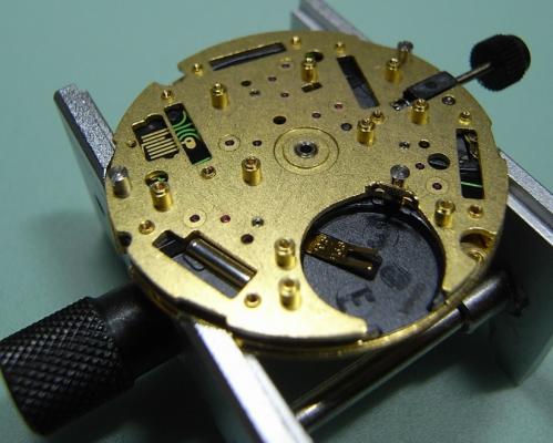
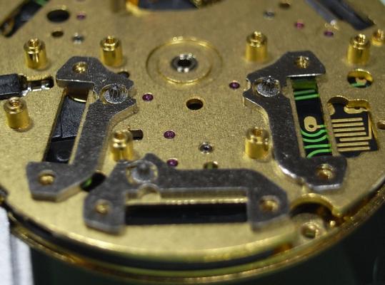
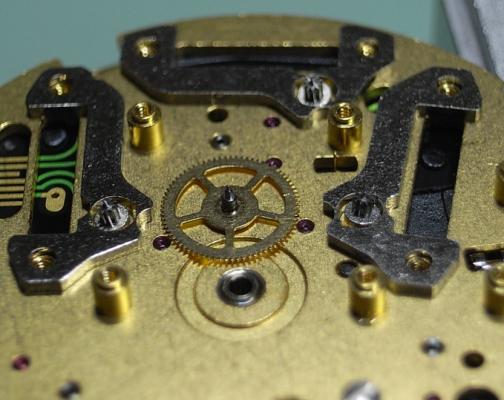
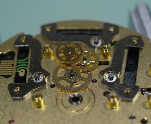
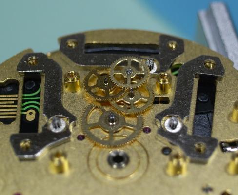
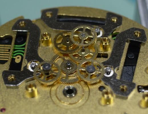
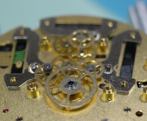
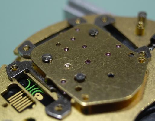
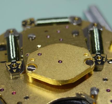
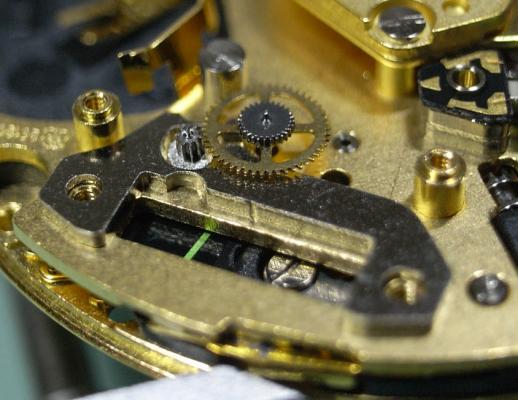
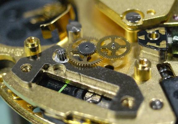
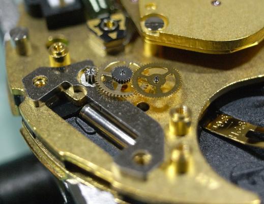
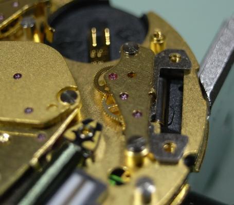
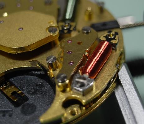
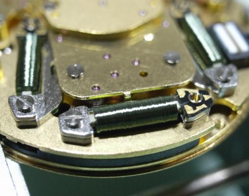
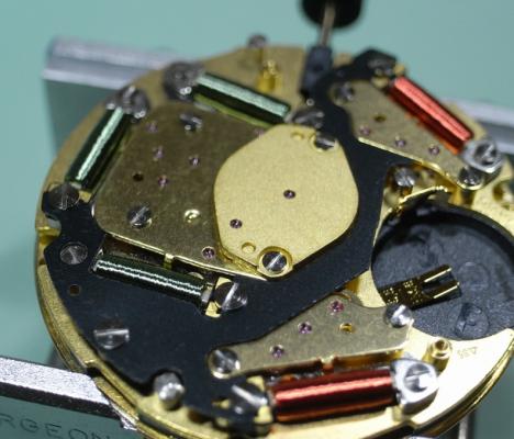
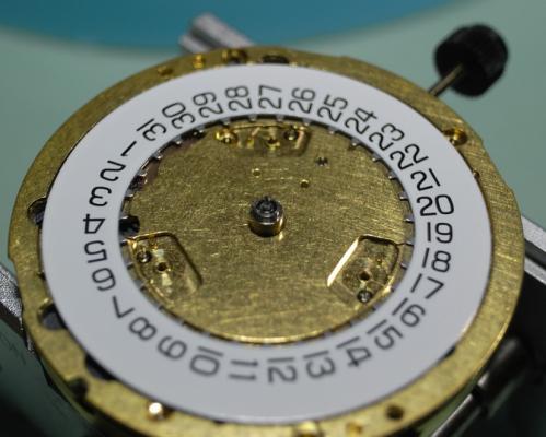
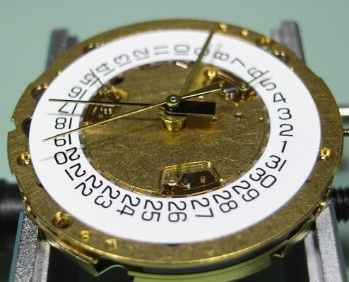
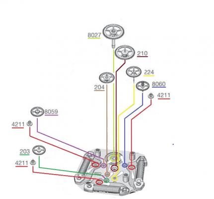
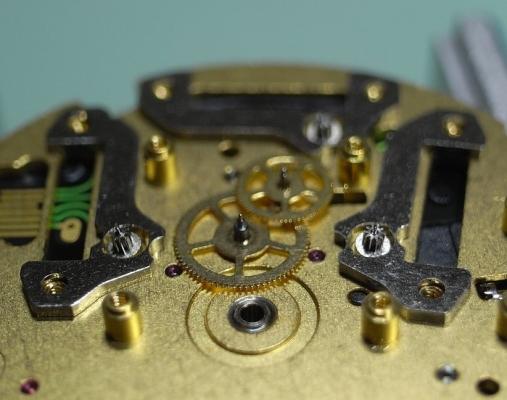
ETA 251.626 Service Walkthrough Part 2 Assembly We begin the assembly with the keyless work. Fit together the Setting Lever and Setting Lever Jumper. Then install the Driving Wheel, Intermediate Setting Wheel No.1, and the Setting Wheel Install the Yoke Then slide the saddle at the end of the Setting Lever Jumper Arm into the groove in the Intermediate Setting Wheel No.1. You will have to then lift the Intermediate Setting Wheel No.1 slightly to position the Setting Lever Assembly as shown below. Then locate the Setting Lever and Jumper onto their respective posts and slots. Once screwed down engage the position arm of the jumper onto it's post on the Setting Lever. Next install the Date Indicator Driving Wheel. Remember that you need to slide back the Date Jumper Once the Date Jumper is back in position check that the spring arm is once again down in it's correct position. Install the Contact Intermediate Wheel, the Hour Wheel and then the Minute Wheel. Replace the Electronic Module, then fit the Sliding Pinion and the Stem. Install the Cannon Pinion with Driver. Replace the Stop Lever/Switch. Then gently place the Upper Plate back on the movement, making sure the Yoke and Setting Lever are positioned correctly, and that you do not disturb any of the other components underneath. Refit the bank of Stators and Rotors which have the Green Coils. Now we come to the trickiest part of this service: installing the Main Gear Train. To assist in the order in which to install the wheels I will give the part numbers, and colour code the text, to match that of the diagram above. Start with the Third Wheel [210]. Then the Additional Intermediate Wheel [204] Then the Second Wheel [224] Then the Intermediate Wheel [203] Then the Driving Wheel for Second Counter [8059] Then the Driving Wheel for Chronograph Wheel 60s [8060] And lastly replace the Counting Wheel for Seconds or Minutes [8027] Once the train is in place, take some time to tweak the wheels so that are standing up as straight as possible. Remember that you have 10 pivots to align with their respective jewels, so taking some time to position the wheels and rotors now can save you a LOT of frustration fitting the Train Wheel Bridge. I would go so far as to take a little break, have a drink, relax your muscles and mind before proceeding to the next step. Fit the Train Wheel Bridge and align all the pivots to their jewels, and check the free running of all wheels before tightening down only the 2 rear screws. Install the Chronograph Wheel. Next fit the Chronograph Bridge and align the 2 pivot points to their jewels. This has to be done without the ability to manipulate the wheels directly, so make sure you inspect the jewels with high magnification to be sure the pivots are in their holes. And again, check the free running of the train. Replace the Connector Next we will install the small trains for the Counting Wheel, 1/10s and Hour Counters. These are the ones with the Red Coils driving them. Remember that the wheels are specific for each train and should have always been separated ... DO NOT MIX THEM UP. We shall begin with the right side. Install the right side Stator and Rotor for the 1/10s Counter. Next replace the Driving Wheel for Counting 1/10s [8059/1] Then replace the Counting Wheel, 1/10s [8027/1] Note this has 4 spokes to the wheel. Fit the Counting Wheel Bridge, making sure to align the pivots and test the free running before tightening. We repeat the process for the left side Hour/Minute Counting Train. Install the right side Stator and Rotor for the Hour/Minute Counter. Replace the Hour/Minute Counter Driving Wheel [8630/1] Then replace the Hour/Minute Counting Wheel [8600/1] Note this has 3 spokes to the wheel. Fit the Hour/Minute Wheel Bridge, making sure to align the pivots and test the free running before tightening. Fit the Red Coil to the right side Counting Wheel Assembly and screw down. Fit the Red Coil to the left side Counting Wheel Assembly and screw down. At this stage also screw down the 3 Green Coils. Refit the Additional Printed Circuit. Replace the Magnetic Screen. Secure the Battery Clamp. Then turn over the movement to the dial side. Fit the Date Indicator. And secure the Date Indicator with the 3 Indicator Maintaining Small Plates. Then fit the dial and hands and test all the functions of the movement. ETA 251.262 operating instructions.pdf The service is complete. As always, I hope this walkthrough was informative and instructive, and gives you the confidence to complete this service on your ETA 251.626


 1 point


.jpg.6225a64433578a11e0218b27c20b13f5.thumb.jpg.d82b0cd1e370f3a3a59a06afa957d184.jpg)