
D. I. Y. Watch Timing Machine.


-
Similar Content
-
-
Recently Browsing
- No registered users viewing this page.
-
Topics
-
-
Posts
-
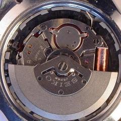 Here are the pics of the bridge. Looks correct, but as soon as I screw on the rotor, the watch stops. Video here: https://1drv.ms/v/s!ArG5E62RGctxjokY5ws85BzuJLVakA Pics.
 -
By KarlvonKoln · Posted
One-dip or naphtha should be safe, but are you sure it isn't magnetized? I would also check that. Although, if that balance is from an Elgin 760 0r 761, I would think it would have a hairspring of non-magnetic alloy. -
 Hi, Is there a spell check function available when you are posting ? Regards CJ
 -
Hi John I just did a Seiko Lord-Matic a front loader without a split stem, I used a crystal lift to remove it, although I had to have it that tight I though I was going to break the lift before the crystal would budge. So I decided that the press would be a better option as I think crystals with tension rings resist a lot of compressing. I used a crystal press to repalce it and the bezel with no issues, obviuosly a different watch to the Omega. I just took my time and kept inspecting the installation progress bit by bit Regards CJ
-
 Hello All, I’m replacing the crystal in an Omega Dynamic, # 165.039, which houses a cal 552, installed through the front of the case. The replacement Sterncreuz crystal is, like the original, with tension ring. I removed the crystal using a compressed air technique to pop it out. (I have a crystal lift, but I’m always fearful of marking the crystal edges and so avoid using it as much as possible). Now to the replacement - any tips on putting the crystal back in? Am I obliged to using my dreaded crystal lift to complete the task, or how about a crystal press? I’ve put lots of crystals in using a press, but never with the movement in the watch. The thought of using one with a front-loader makes me very nervous, with the fully assembled watch sitting under the press. How would more experienced folks proceed here? Any advice, gratefully received… John Down Under…
-


Recommended Posts
Join the conversation
You can post now and register later. If you have an account, sign in now to post with your account.
Note: Your post will require moderator approval before it will be visible.