
Gearotic V3 to design Gears for Repair

-
Recently Browsing
- No registered users viewing this page.
-
Topics
-
-
Posts
-
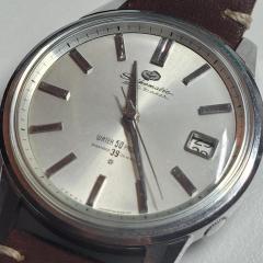
 So it's what people call a Citizen C Mark and was the first centre second movement they produced in 1950. This lines up with the serial number which dates yours to March 1951.
 -
 Hello I'm trying to install the Hour Counting Wheel assembly in a Valjoux 7750. The issue I'm having is the Hour Hammer Wheel keeps fouling on the Hour Hammer and the Hour Hammer Counter Lock. I believe it's because the Hour Hammer Counter Wheel is pinned to the Calendar Bridge. The latter prevents me from installing the Hour Hammer Counter Wheel separate of the bridge and seeing how it interacts with the other Hour Hammer components. These are my questions: 1.) Should I take the pin off? The one holding the Hour Hammer Wheel to the Calendar Bridge? 2.) Can this pin be removed? 3.) Any tips for installing the whole assembly if I'm not meant to remove the pin? I've included pictures to better illustrate what I'm writing about. Thanks in advance for any help that can be provided.
 -
 The crystal seems to be exactly the same as the old one, bought from Cousins using the model number of the watch. I tried again to manipulate it into the case but still having no luck. I think I will have to reduce the size slightly but am worried that once it's in, it could be loose. Before I do that I think I will try and design a custom shaped die for my crystal press and 3D print it.
 -
 What you’re saying is that if the entire coil is lifted or tilted either up or down it is due to a slight twist in the spring? Usually next to the stud? I’ve chased this before and in one instance the spring came out of the stud and I had to reinstall it and secure it in place. Do you find that the angle (not twist) the spring leaves the stud not only affects how it centers in the regulator pins but also the coil spacing? This could be caused by a distortion in the spring as it grabs and release the pins. I find turning the stud counter clockwise opens the coils 180 degrees away from it. So do I adjust the stud in relation to the regulator pins or to the coil spacing? I also find that unless I remove the balance from the cock I can’t see the slight distortions in the spring. In my picture the distorted spring looked fine when installed. Do you use Alex’s technique of sliding the regulator arm up and down the curve to find distortions or can you visually see them? Gettin back to positional variation for a moment. The angle of the regulator block is set by the factory and I’ve noticed it’s always the same. I have seen that sometimes the pins are too closed and grab or can grab the spring. If you open the pins to do the curve check what guide do you use to close them back down to the correct angle?
 -
 So if anybody overrides what i say, listen to them haha. I'm not an expert but i've just been in this boat a dozen times as i used to mess up hairsprings bad, but the good part of that was that i got to learn how to fix them. What made my life SO much easier was learning how to adjust the hairsprings with the balance installed on a disassembled mainplate, unless it's a very serious problem or on an inner coil you can't get to i would recommend trying this in part because the spring will mostly ALWAYS look flat when the balance wheel is not installed on the cock. Install the balance wheel back in the cock and the cock with the cap jewels in the mainplate, with it installed even the most imperceptible twist will be pretty obvious. Just make sure the balance jewels are also installed. In these movements, if 99% of the time any twist or problems gonna be around the terminal curve, twists often near the stud, especially if you've been removing their awfully designed studs from the balance cock. If there's a reliable way to install those things without introducing a minor twist to them i haven't found it. they're an awful design. INstall the balance on you mainplate WITH your capstones/chatones and look sideways across the balance under magnification. Look for the highest or lowest spot of the now not flat hairspring. 180 degrees from that high or low spot is where your twist will be. You have to be VERY careful with twists as the tiniest over or under twist brings it out of flat. If the area i have to untwist is near the stud i just use a pair of #5 tweezers or some very sharp fine curved tweezers and gently see which way i twist it corrects the twist, then i hold the very fine point of the tweezers on the hairspring and just gently squeeze and check it and see if it started to correct it, then i rinse and repeat. Tiny adjustments is what you want, don't close them all the way, and dont' introduce a flat spot in them. it's just a little nudge by closing the tweezers on it at an angle. . If the twist is not near the stud, i grasp the hairspring with some very fine curved tweezers as gently as possible while still holding it then i do that same sorta tweezer squeeze with my #5's.
-

Recommended Posts
Join the conversation
You can post now and register later. If you have an account, sign in now to post with your account.
Note: Your post will require moderator approval before it will be visible.