Leaderboard


Popular Content
Showing content with the highest reputation on 10/04/18 in all areas
-
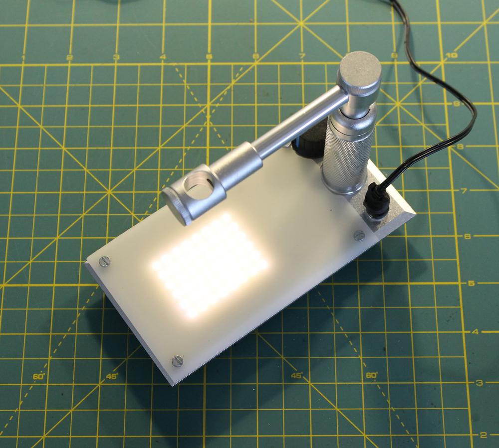
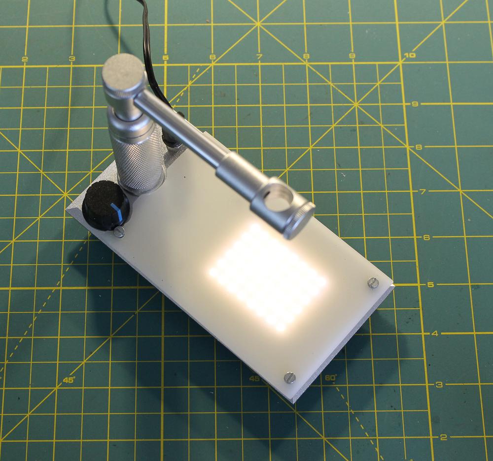
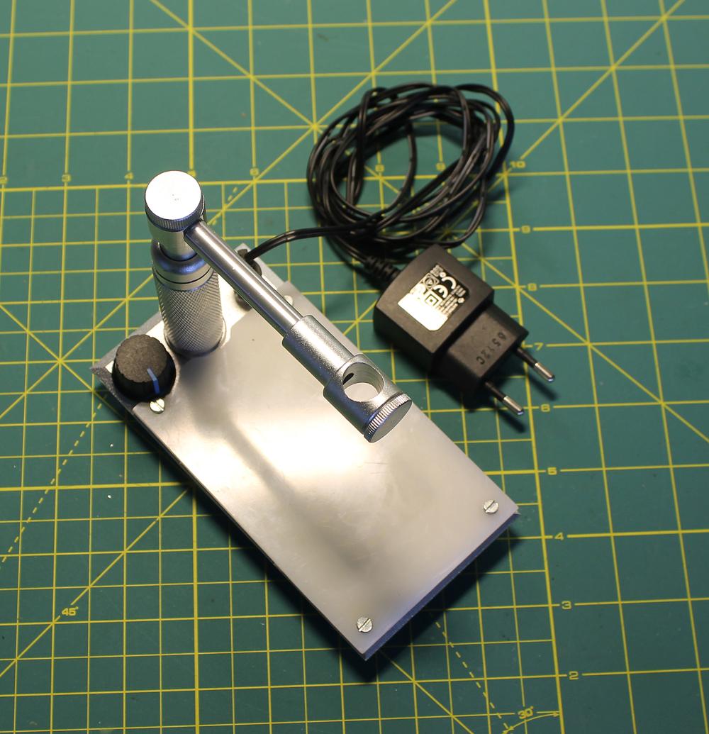
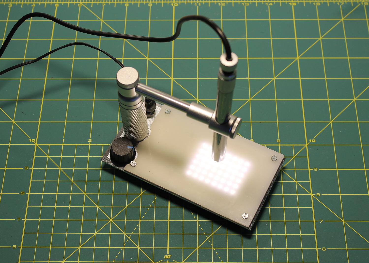
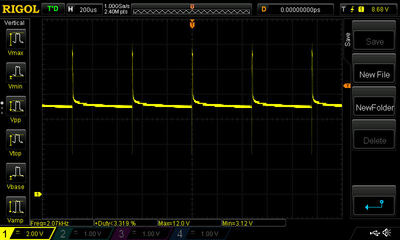
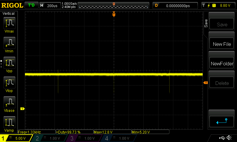
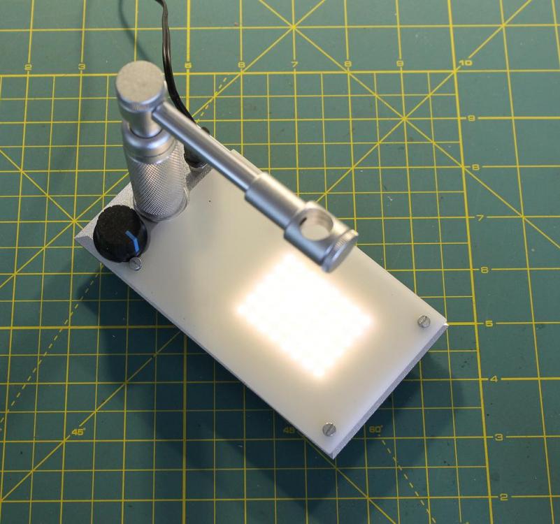
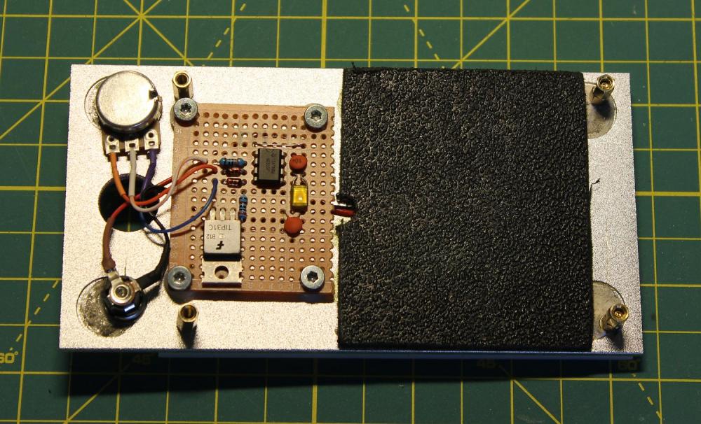
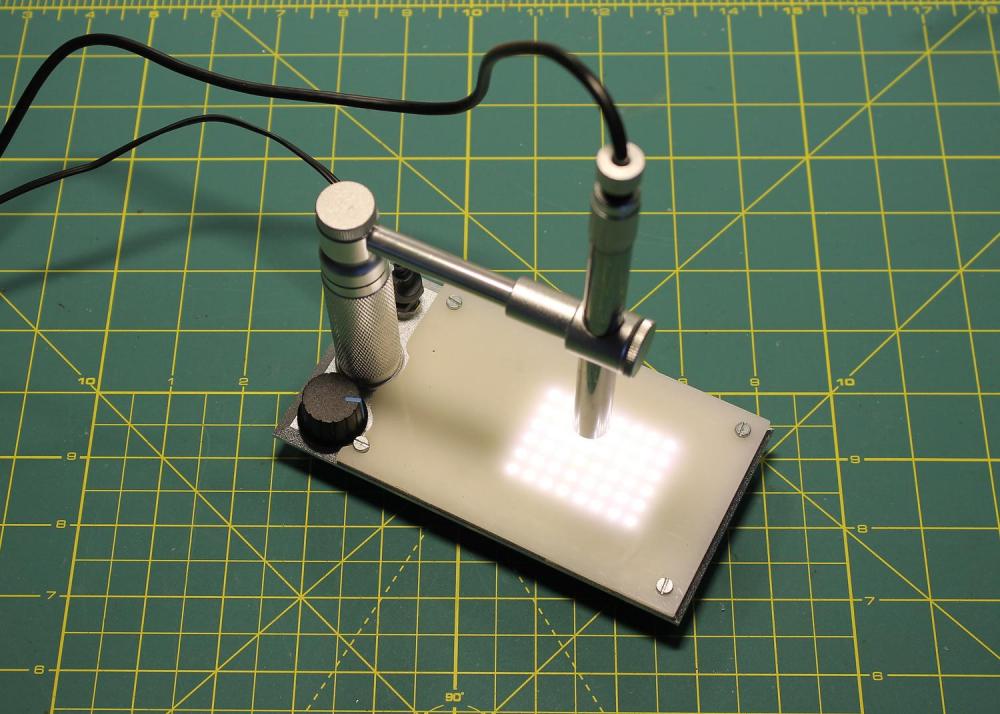
Before putting the components on a print-board, I measured the frequency of the pulses with an oscilloscope. Depending on the position of the potentiometer, with the components in the above schematic, the 555 triggered between 120 Hz and 300 Hz. To avoid any chances of flicker on a video, I changed C1 to 1nF and R2 to 680 Ω. The capacity of C1 gets lowered and by lowering the resistor R1, the capacitor will be even faster drained, causing the 555 to trigger faster. The frequency increased to a range between 1.33 kHz and 2 kHz, with a duty cycle between 3% and 99 %. The modification of the base-plate took a little longer; the design took shape while I went along, trying to keep everything as compact as possible and near to "original"-shape when the base-light is not required ....... This meant the potentiometer to be positioned to the left of the column, a power-plug to the right of the column and the circuitry below the slightly raised base-plate. If the base-light is not required, all what needs to be done is to unplug the power supply and the microscope abse-plate is back to "original" (well, .... nearly ) 12 Volt turned out to be too bright, so I ended up wit a 9V DC adapter, reducing the highest brightness and also lowering the lowest brightness to nearly nothing. Seemingly an excellent range ....... And here the circuitry tucked underneath the base-plate, all components build flat on the PCB to avoid any damage. The 4x corner studs (one adjustable to take out any "wobble") do also act as an anchor point for the 4x screws holding the white transparent plastic on top. The PCB is by means of 4x nylon spacers slightly raised above the bottom of the base-plate, to avoid shorting out on the aluminum. All seems to work fine. If I one day stumble over 4x countersink M3-screws, the current screws will be changed out so the top will then be flush. Another project done .......


 1 point
 -
If it's a Swatch Irony then they made many different models! You only have to put the keyword 'irony' in the Swatch Watch Finder (https://www.swatch.com/en_us/watches/) to note there are 1922 matches! An educated guess is therefore that it's not '1R' in your numbers but 'IR' for Irony (?) and the numbers are then an internal code simply to ensure a tie up to a particular model. Maybe.1 point
-
yes you are....;)1 point
-
Hi Alex and welcome. Looks to me like you are well on your way to a new hobby. Books! Look at de Carles Practical watch repairing and Frieds Watch repairers Manual , I still refer to them. All good wishes. Regards Mike. The old Watch Jobber.1 point