Leaderboard


Popular Content
Showing content with the highest reputation on 08/03/15 in all areas
-
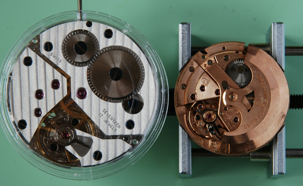
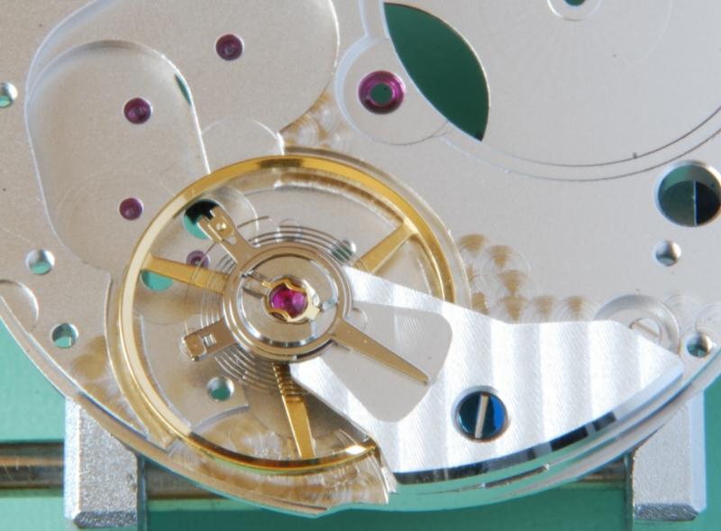
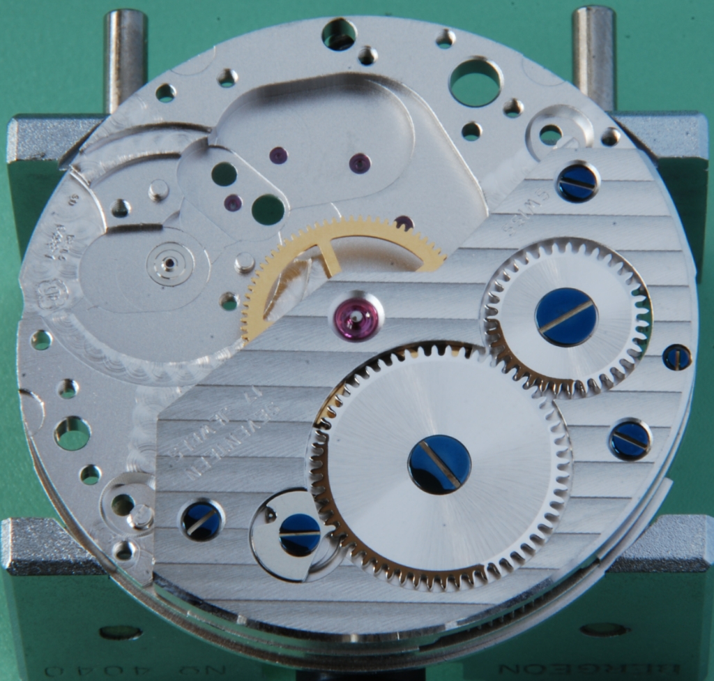
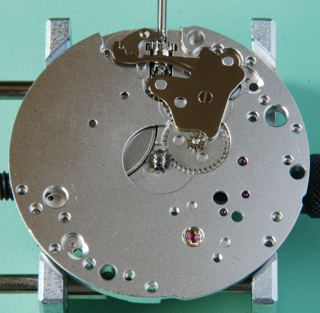
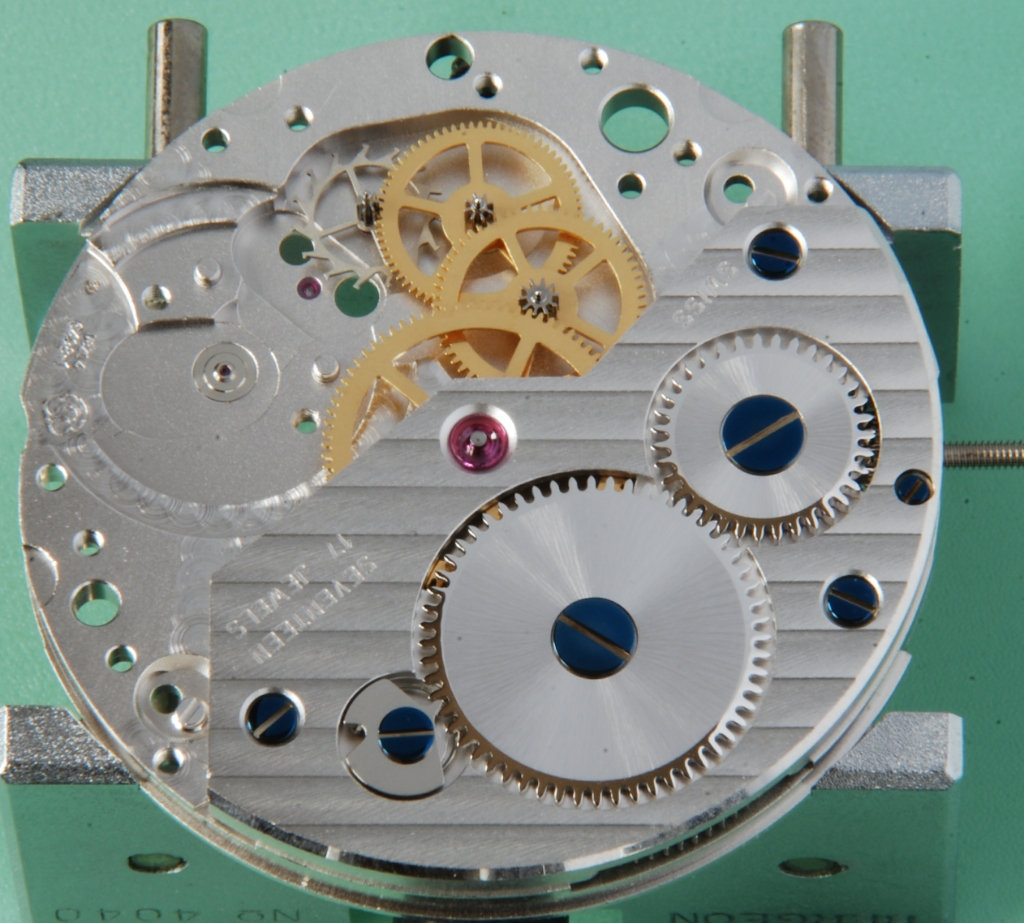
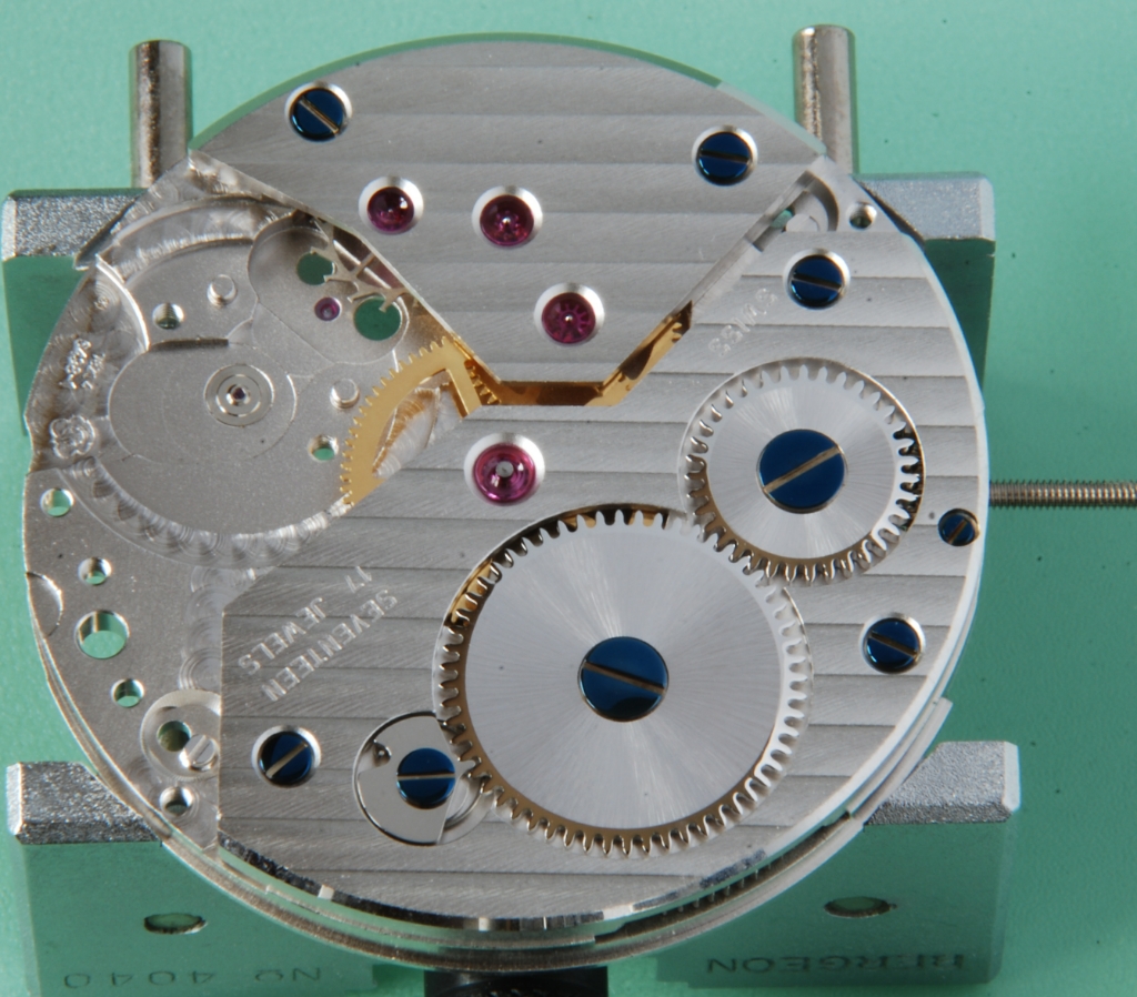
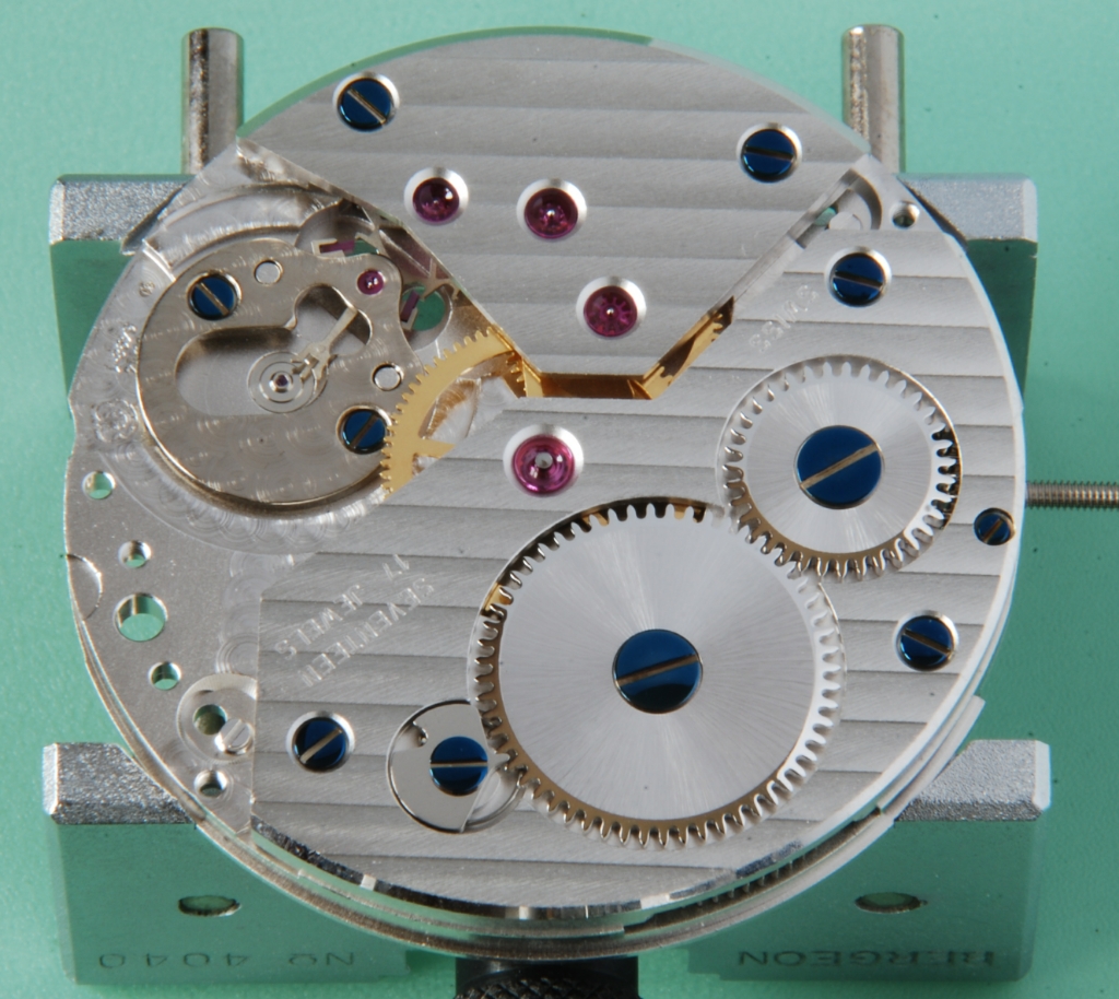
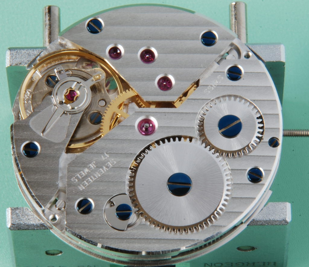
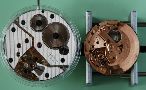
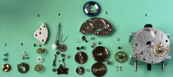
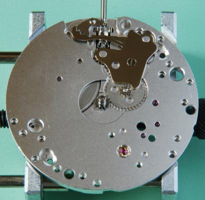
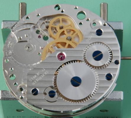
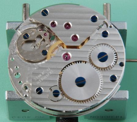
Hi I've just joined the forum so by way of an introduction and where I am in this hobby, I'm posting this build of a 6498. It's not a full walkthrough but this forum seems the best place for it. I usually work on older watches but have been meaning to have a go at one of these for some time and received a 20% discount offer from PayPal so I picked up an ETA6498-1, dial and hands on eBay. The case came from elsewhere. There are loads of people selling these as kits to build your own watch. This is just about the most basic movement you can buy, with no complications. There are two calibres in the family, the 6497 has the sub second counter opposite the crown so at 9 O’clock and the 6498 sub seconds is at 6 O’clock which I prefer but, the two calibres are very similar with many shared parts. Servicing one of these simple ETAs is probably not a bad way to start. I didn’t do that but, thought it might be nice to work with a new movement for a change and play with the Etachron system. To the best of my knowledge, these movements come in four grades: Standard; Elabore; Top and Chronometer. The lower two grades are easy to buy so that's what I have. The top two are not so readily available. It’s big at 36.6 mm diameter so, minimum case size must be 41-42 mm diameter as that’s a case wall of 2 mm only. People use these in cases much bigger than that but, I chose a 42 mm case as my wrist is only 6.75”. Here’s the spec for my grade and a bare movement picture (in its plastic case) next to a very dirty Omega 565 spares movement which is 28 mm diameter. Manual wind, 46 hour reserve 17 jewel and Incabloc shock protection with Etachron system. 18000 A/h (2.5 Hz) frequency It’s possible to buy these in a foil sealed pack (I think packed with an inert gas) and use straight from that pack but most, like mine, are sold ‘loose packed’ so should be serviced before use. I will do that and also see if I can improve a little on the way it runs straight out of the box. ETA publish a set of service instructions for this calibre with types of oils and an assembly sequence and the pdf is readily available. I more or less follow that assembly sequence. For the performance, to set a datum, I wound the movement, let it run for a day and then tested the 24H and 0H conditions. The CH, 6H and 9H are the only specified test positions for this calibre but, I tested over all six positions. Results as follows: Amplitude: max 290 degrees at 0H and min of 220 degrees at 24H. Six position delta: at both 0H and 24H of 18 seconds. Beat error under 0.4 milliseconds. These are pretty good and almost chronometer spec so I will try and get within that, being delta of 12 seconds at 0H and 15 seconds at 24H. On the older Omega movements such as the 5xx series, some are chronometer rated (e.g. 561) and some are not (e.g. 565). I remember looking at the parts commonality between these some time ago and I’m pretty sure that there were no differences in the critical parts so, those usually will come close to that spec. On this 6498, the balance and balance spring seem to be the major differences to guarantee chronometer spec for the better movements. Well, I have the cheaper one so, we’ll see. First is to line up all the big screwdrivers as these started as pocket watch calibres so, all the screws are big for me. Stripped and cleaned, the parts are these and this shows this is a simple movement. The parts are in seven groups working from the right. This is not a blow by blow account but I took some pictures to show how it goes together. These are all the pieces. 1. Plate with balance still mounted. 2. Incablocs and second wheel/cannon pinion. 3. Mainspring, barrel, ratchet wheel, crown wheel, click and barrel bridge. 4. Keyless works. 5. Train wheels and bridge. 6. Pallet fork and bridge. 7. Case clamp screws and hour wheel. First to go on are the Incablocs. I don’t know what reflection is being picked up on the machined parts of the plate but there is no discolouration at all in reality. For those in the know, I have the curb pins wide open as I am adjusting concentricity and centering of the hairspring between them. Really, for me to improve this movement performance, I can adjust the wheel shakes and try for the best configuration of the hairspring so, I spent a little time here. No poising of the balance at this time. Nice to have an adjustable stud carrier to set the beat error. This Etachron system is quite clever and it’s pretty new for me. It certainly reduces the amount of hairspring work which is not my favourite. I know it's not universally liked but it seems pretty neat to me. I end up with a very slight turn on the stud holder after some playing and am happy so, close up the curb pins again for final tweaking when it’s on the timing machine. Second wheel and cannon pinion fitted. Mainspring mounted in barrel and the complete barrel and barrel bridge mounted with its three screws, not forgetting to fit the setting lever screw first (!) which must go in before the bridge. Ratchet wheel, click and crown wheel fitted. It’s quite an attractive finish and the blued screws are a nice contrast. Turning over and the keyless works are fitted. I was a little generous with the grease here. This side of the plate is not so well finished but will be hidden under the dial so not so critical. Nice that there are holes in the minute wheel to allow the train oiling later. Here the rest of the train is shown, third, fourth and escape wheels. And now the train bridge mounted with its two screws. A little bit of wheel shake checking here but, it’s very good. Then the fork and bridge are fitted. That bridge is not the most attractive but it’s usually obscured by the balance. Checked the fork locking and so on here and no adjustment needed. Finally, the balance goes back in and the movement lives again. I let it run for 15 minutes and then removed the balance to oil the pallet jewels with 9415 (out of interest, I'm only using Fixodrop on the escape wheel and pallet jewels). This is an easy job on such a big movement but trickier for me on a very small ladies calibre. I have an Omega 684 in my wife's watch which is about 2/3 of the 565 size. After running for 24 hours again, I made some tweaks to the curb pins to equalize the horizontal and vertical running a bit better. Now, the six position delta is 10 seconds at both 0H and 24H so, I’m very happy with that. This really is a terrific movement for the money in my opinion. Bit more to follow later with (huge) case, dial etc. Hope some of this is of interest. Cheers, Chris


 3 points
 -
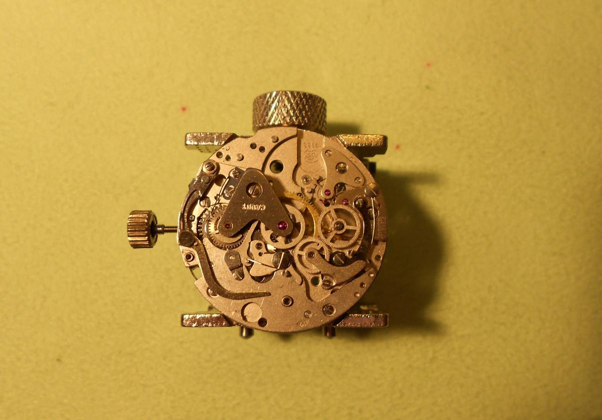
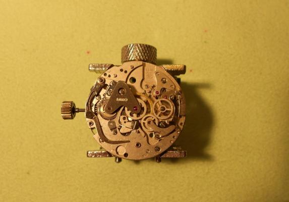
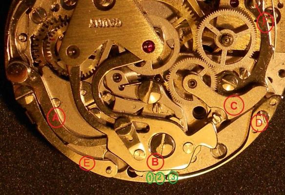
The VALJOUX 7733 is ticking again!! After the precious help of GeorgeClarkson for fitting the operating-lever on the chronograph plate, I went on assembling my chronograph. It was not easy for the rookie I am, but after several "try-error-try again" events and some hours spent on it, I finally managed to see it working again. The main issue was getting the different operating-levers working together in a synchronized way. My conclusions about the way to get it working: I) The position in which rests on the plate the operating-lever (the one actuated by the start-stop button) before putting in place the so-called hammer is important and should look like this: II) The hammer (piece B in the next photo) should be fastened in the plate so that the hammer-cam jumper be in position 1, (that is in the normal chronograph working position after pushing start button). III) After having assembled the operating-lever A, the hammer B, the hammer-cam jumper D and the fly-back lever E, the correct movements of all the system when pushing the start/stop and fly-back button must be verified, prior of assembling the coupling-clutch C. IV) The coupling-clutch C should be assembled with the hammer B in position 3 (the actual position in the photo) corresponding to the return to zero position after pushing the fly-back button. V) After completing all the remaining assembling operations (putting in place the driving-wheel flush with the couplig-clutch, the balance wheel, etc,), and after getting the watch ticking, you can use, if needed, the cam F to fine tune the depth of the gearing between driving-wheel, clutch wheel and crhonograph second counter wheel. (of course I took care of all the lubrication tasks for the different parts during this assembling procedure) I can not guarantee that this is the best or the easiest way to get the chronograph levers operating correctly, but this was the way I managed to do it. And now I only have to overcome two more issues to get the Cauny complete. The first, I already told you about, is the chronograph minute-counter hand (I'll follow CKelly sugestion to overcome it), the second it's again my fault as I broke the Incabloc spring in the balance wheel pivot when I was trying to get it off !! ...Natural for a newbie, isn't it ?! (I apologize for not having taken more photos during these procedures but I was so entertained with the job, and anxious to get a result that I forgot it!)
 2 points
 -
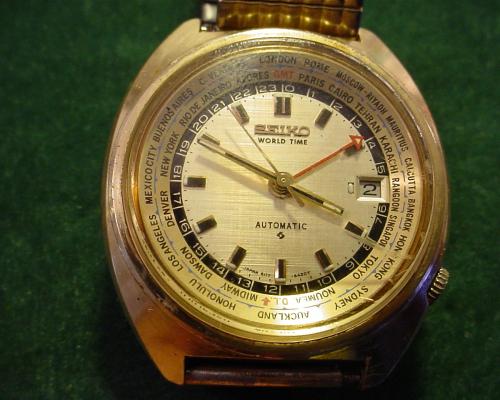
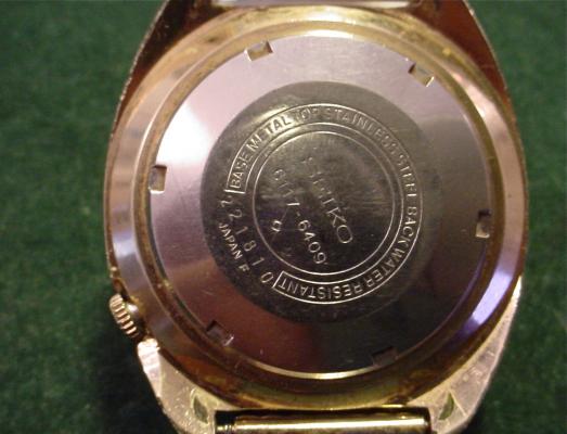
Hi All , I went to the Swap meet at Aloha stadium today and found this Seiko 6117-6409 World Timer made in Feb. 1972 . It's running and keeping time so far . The inner bezel with the cities rotates as it should and the GMT hand is also working . It has a Linen Dial and the watch is in good overall shape . The only flaw I can see is a scratch in the acrylic crystal that I can easily clean up but I made a bid on a new Seiko crystal . It has a generic expanding watchband , but I may get a dark blue leather or blue suede watch band . I'll look around for that and see what suits the watch ............I was able to pick it up for under $50 .
 1 point
 -
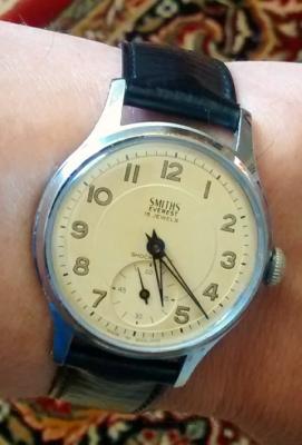
Hi Guys I've been reading this forum off and on for a while after a recommendation from Geo so, thought I'd register and say hello. I've been doing this as a hobby for a couple of years. Most of my watches are 60s Omegas but, I'm wearing a 60s Smiths today and always wise to start with a photo. Hope to be able to get involved a little. Regards, Chris
 1 point
 -
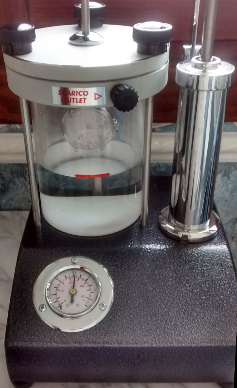
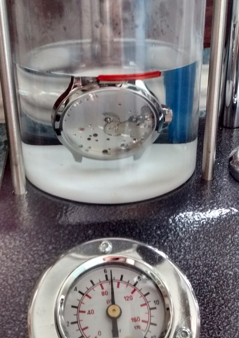
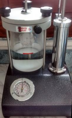
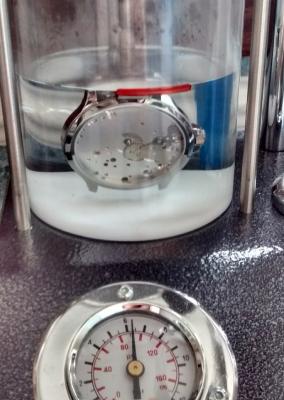
Thanks Geo. A little more. I bought this quite smart case with display back as I liked the crown guards and that it's only 42 mm. It still makes a huge watch as it's all dial. Anyway, the hands were delivered with C1 lume (the white one which was what I wanted) and the dial with C3. That had to go back which was during their company holidays..... So, thought I'd pressure test the case. It's rated at 50m or 5 bar (75 pounds per square inch, psi) so I tested at 25% above that. Here with the case above the water and 6.25 bar showing (92 psi). If the watch leaks, then the pressure inside it equalises to 92 psi and when the pressure in this plastic cylinder is decreased, the air will come out of the watch so, before releasing the pressure, it goes into the water. Then, bubbles will be seen. None showed here as the pressure was slowly released so, it seals fine. I forgot that picture. There is a big problem with these sort of testers. If you drop the pressure quickly and the case has let in that pressure, then you can blow the crystal out submerging your nice rebuilt movement in the water. So, I always test first with an empty case. I've had one crystal blow doing that.... Just thinking of the force involved, this crystal has an area of about 1.5 in2 so, if there was a delta pressure of 92 psi, that would be nearly 140 lb. I usually push old crystals out from behind with my thumb so, they would clearly pop out under a tenth of that force. Anyway, it's slowly coming together! Cheers, Chris
 1 point
 -
Reading through this thread I get just the slightest feeling that there is some confusion over nomenclature and it's important not to be mistaken. The ratchet wheel is the wheel with the square hole that is attached to the barrel arbor, and against which the click usually operates. This wheel usually has a right handed thread. The wheel that often has either a left handed thread or two off centre screws (right handed) is the crown wheel, which is the wheel that turns the ratchet wheel. Please note the use of italics here as it is an area of design that does vary and these screws should always be treated as self destructing until you know which way to turn them. The reason for having a non-standard arrangement for the crown wheel screw is that the screw does not rotate with the crown wheel. If the crown wheel rotates anti-clockwise (as in the AS984), and the crown wheel screw had a right handed thread, then it's possible that torque could be transferred to the screw that would undo it, hence a left handed thread. The ratchet wheel screw does rotate with the wheel so there is no risk of a loosening torque. As such a standard right handed thread can be used which is handy as this allows the use of a screw driver to wind the barrel a little when testing the free running of the train when reassembling without having to install the keyless works first. If the problem screw on this 984 is the crown wheel screw then I would be inclined to think that it is a lefty, if it is the ratchet wheel screw then my money would be on right handed. That being said, I have had left handed threads in the barrel arbor, and right handed threads in the crown wheel, just to keep me on my toes. Proceed with care. Good luck.1 point
-
All, I've posted more reference material on kanddinverto.weebly.com. One item that might be of particular interest is a better table of stumps than I've seen posted elsewhere. The table is posted at http://kanddinverto.weebly.com/inver...hure-1937.html. There's also a secret decoder ring for the table posted at http://kanddinverto.weebly.com/decod...of-stumps.html. Other recent improvements include the addition of dates (or possible ranges of dates) to the various references and reorganized menus that should make things a little easier to find. Regards, Tom1 point
-
Welcome, come and join In with the fun!1 point
-
At least you know what you are dealing with now Roger. I look forward to hearing how you get on. :)1 point
-
Hi Roger, does this help:- http://www.crazywatches.pl/tissot-seastar-2100-omega-1315-quartz-19761 point
-
Here's my take on it Louis, although I may well be wrong. Fit the spring into the back of the plate as in the bottom picture. Place the indexing cam in picture one as far down the slot as is possible. Place the plate complete with spring carefully onto the movement and gently nip up the screws. Use a pair of tweezers to compress the spring while pushing the plate into position with a piece of peg wood. When located behind the cam tighten the screws to hold the plate down securely. I think!1 point
-
Yes exactly that one. Try to lift one side of the lecer (the one NOT with the screw hole) while pushing down the other part, and keep them separated introducing in the middle, near the round knob, a needle or the tip of a screw driver: this will separate them and create the gap you need to insert the lever into the "C" dent. The part of the lever without the screw hole should then be slidden flush on the plate, locking the knob inside the dent itself. Carefully push the rest of the lever onto the base plate so that the hole for the screw aligns on thhe protrusion on the plate, and set it gently. This should lock it into position. Finally, insert the screw and tight it down as you would normally. Check that the lever does function properly before tighting the screw, though1 point
-
You can just PM those to me personally. I have no issue with that :D Sent from my iPhone using Tapatalk1 point