Leaderboard


Popular Content
Showing content with the highest reputation on 02/01/15 in all areas
-
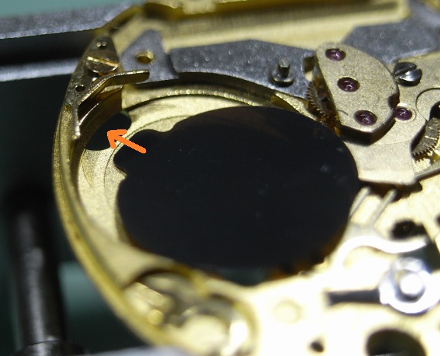
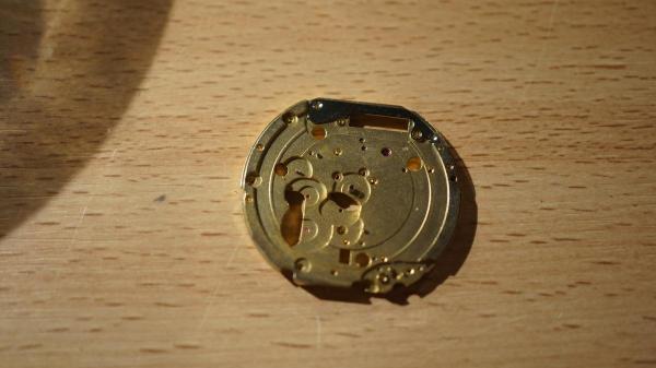
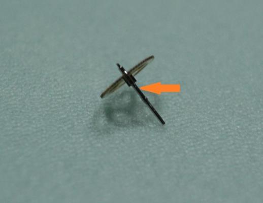
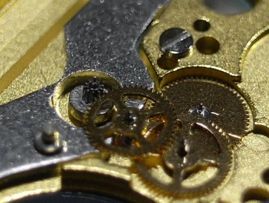
Upper pivot hole. For reasons I won't go into here, I had built a balance assy & cock from 2 separate balances. Turns out that the BFG 866 uses (at least) two slightly different arrangements, and to make a long story short, there was a mismatch between the upper pivot and pivot hole. Things appear to be running well at the moment, but I'm not celebrating for another 48 hours or so - gremlins. Thanks for the thoughts. They helped to get my brain headed in the right direction.2 points
-
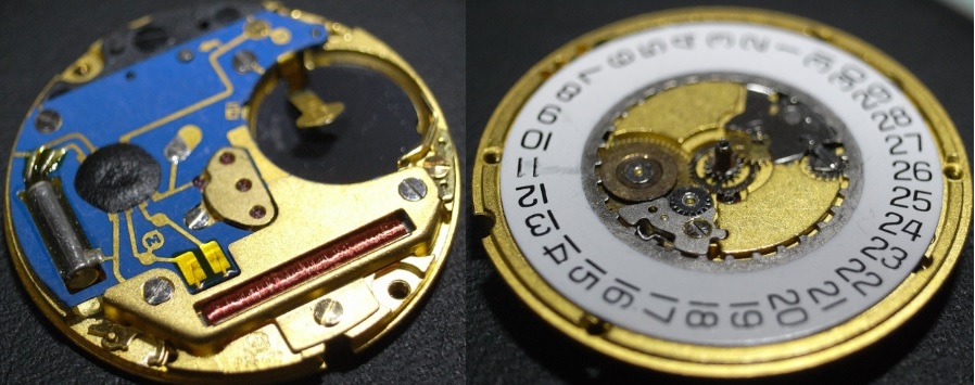
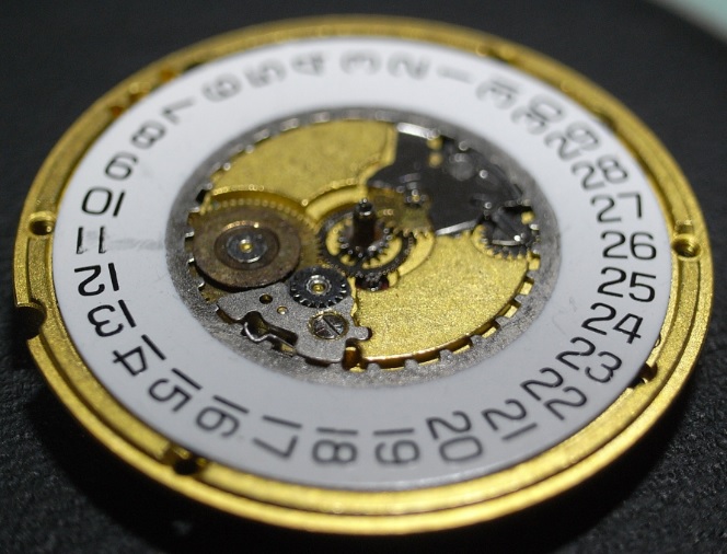
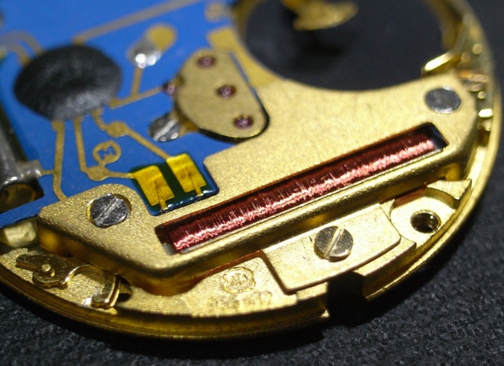
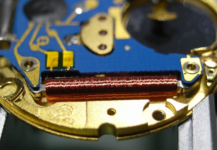
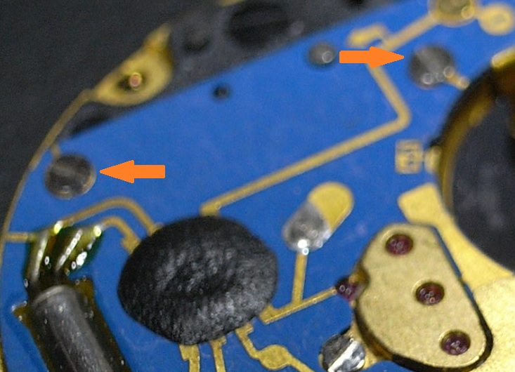
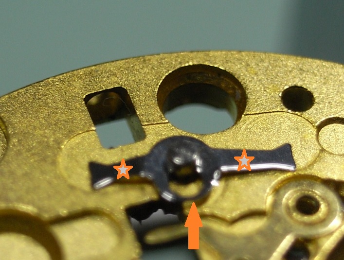
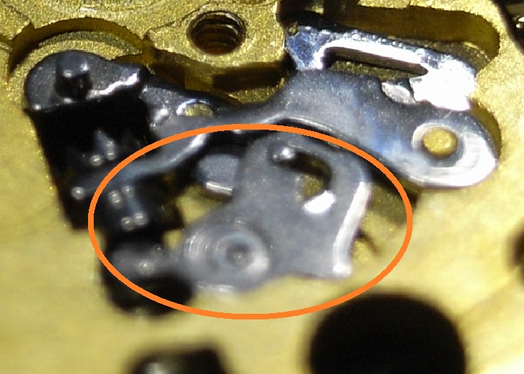
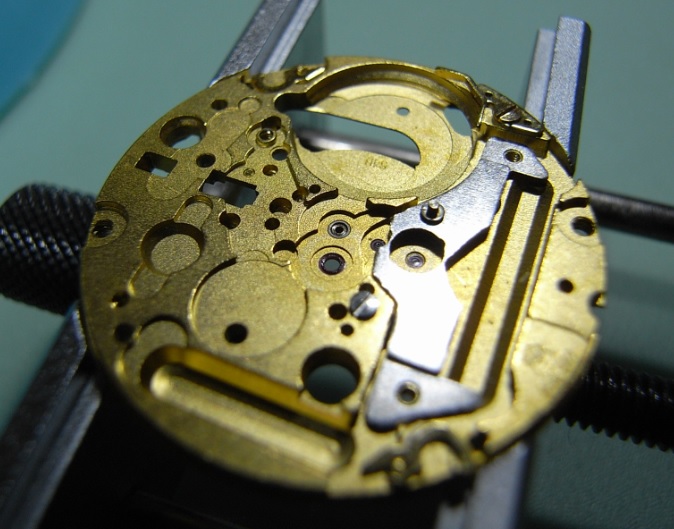
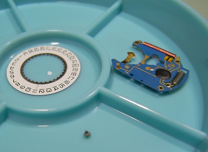
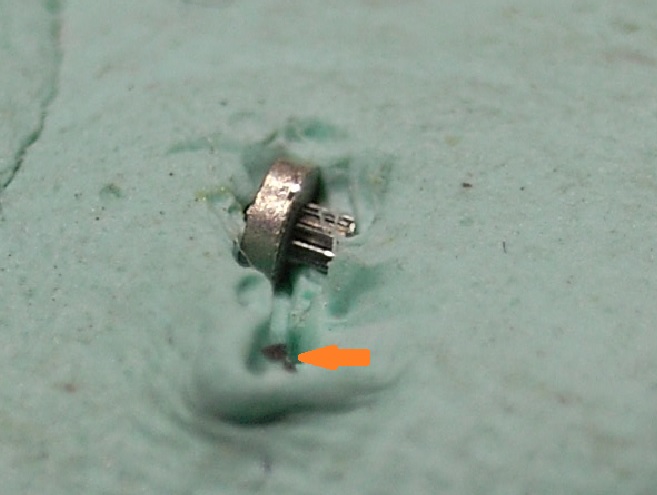
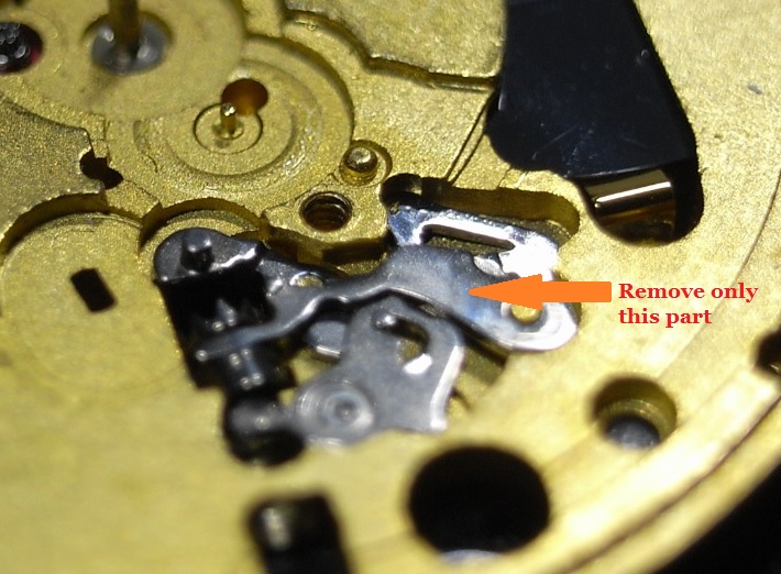
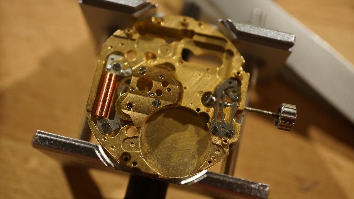
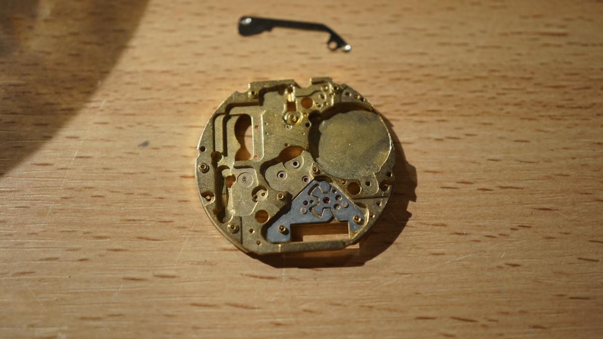
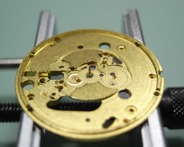
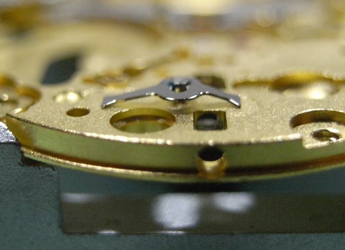
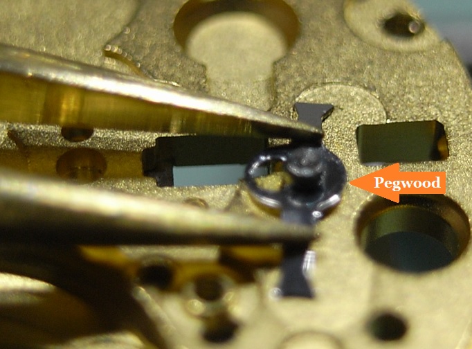
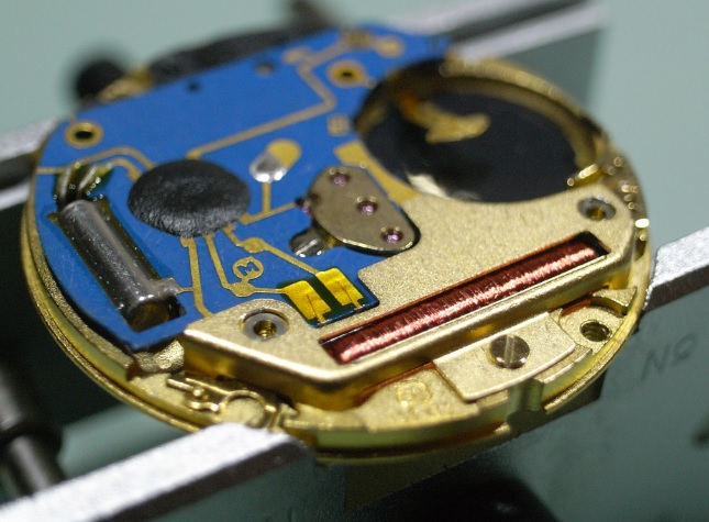
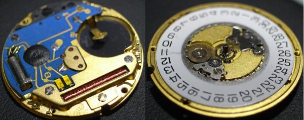
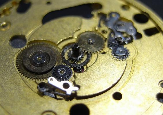
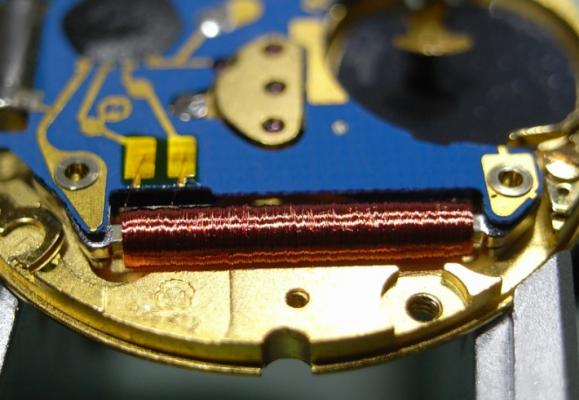
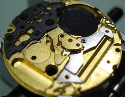
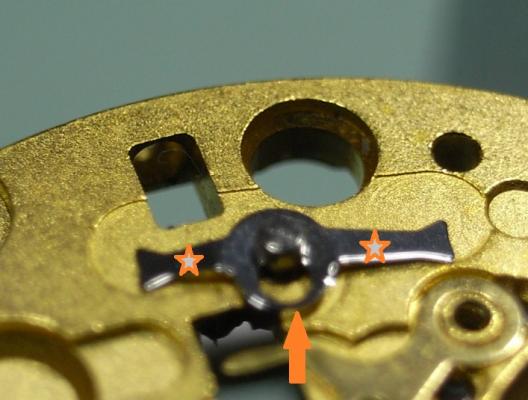
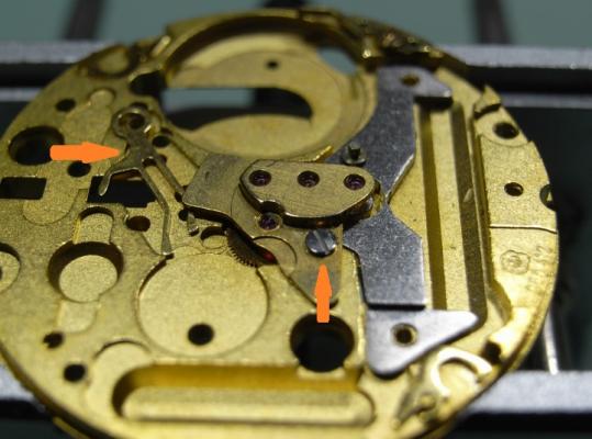
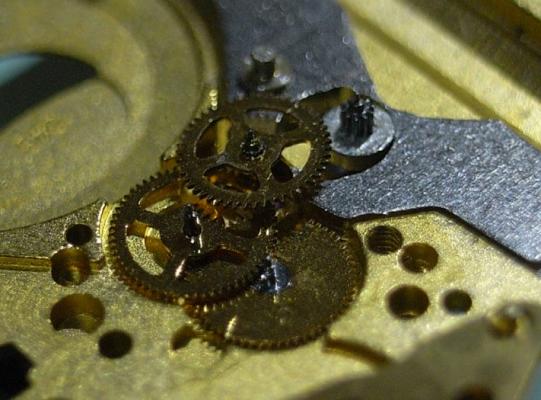
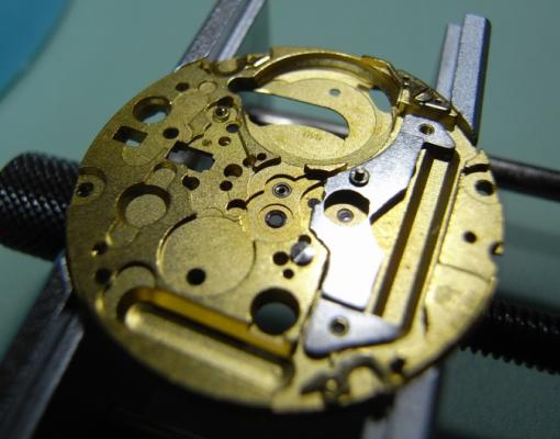
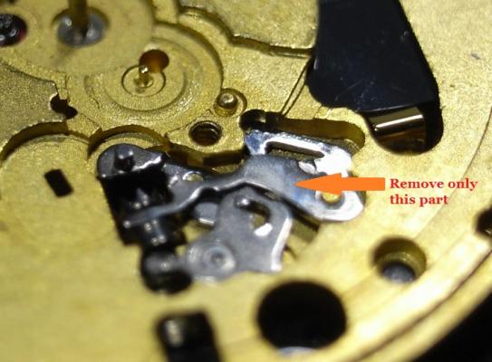
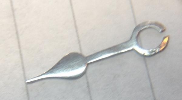
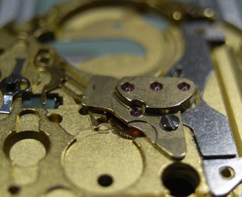
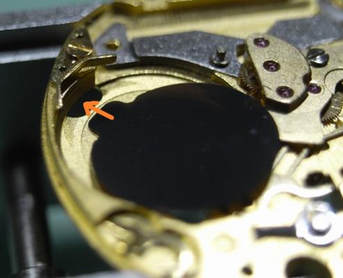
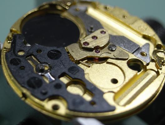
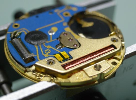
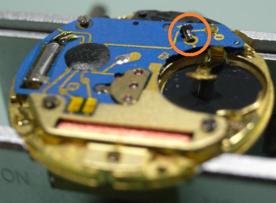
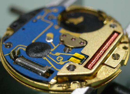
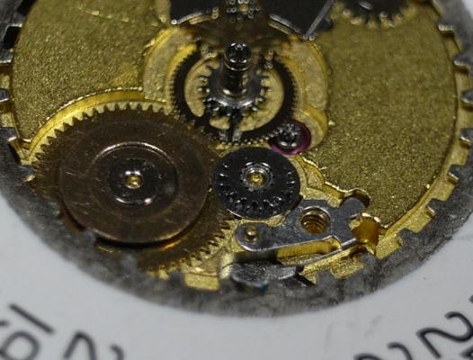
ETA 955 Service Walkthrough "The Workhorse of Highend Quartz" The ETA 955 and 956 Quartz Movements are the most commonly found movement in high-end quartz watches with three hands and a date feature. You will find them in Omega, Tag, and many other brands on the market. For this walkthrough I will be using an 955.412 Movement as my example; but the 956 is so similar to the 955, that this walkthrough will suffice for both. Please note that the numbers after the decimal place only relates to the factory in which the movement was made, so yours could read 955.112, or another factory number ... regardless, the parts are identical and interchangeable. As with all movements, quartz or mechanical, they have a service interval that should be adhered to for longevity of the movement. With quartz movements when the lubrication becomes dried out, or the movement becomes dirty, they will draw more and more current from the battery in order to maintain accurate time keeping. The ETA 955/6, when in optimum condition should draw around 800nA ~ 1.5uA, if the movement is drawing more power than this, a service is required. If a service is not performed, the battery life with decrease markedly, and can go as far as drawing more power from the battery than it was designed for, and damage the battery and cause it to leak and corrode your valuable time piece. Service Manual for the 955/6 Movement CT_956412_FDE_493024_06.pdf.PDF Disassembly Remove the two Date Wheel Keepers. I always start with the one holding the Date Jumper Spring in place. Sometimes the Date Jumper Spring can ping out of place, so be careful when removing the keeper plate above it. Here is a reference photo in case it moves before you see how it's properly seated. Next remove the Keepers and Date Wheel. Then remove the Date Jumper Spring, Motion and Calendar Work. This will leave only the Keyless Work; remove the Yoke and the Sliding Pinion only. We need to flip the movement over, and disassemble the IC Board before we can remove the rest of the Keyless Work. With the movement flipped over, remove the 3 screws holding the Coil Protector. Note for re-assembly the Gold Screw in the centre. Now that the Coil Protector is removed, GREAT care must be taken not to damage the exposed fine windings of the Coil. Then to remove the IC Board, simply remove the 2 remaining screws that hold it. Do this slowly and carefully, as you do not want to slip off the screw and damage this delicate circuit. The same level of care needs to be taken when removing the IC Board from the Main Plate. Take your time and carefully lift it off and store it immediately out of harms way. Next remove the black Insulator Block, and Battery Insulator. This will expose the Setting Lever Spring Clip, which will enable you to remove the rest of the Keyless Work. To remove the Setting Lever Spring Clip, place both points of your tweezers on the locations where I've placed the stars and gently push down on the spring. Then with a piece of Pegwood, push the spring in the direction of the arrow until it moves to the larger opening slot. This will now allow the Setting Lever to be removed, along with the rest of the Keyless Work. Next remove the Stop Lever and Switch, and remove the one screw holding the Train Bridge in place. Then carefully remove the Gear Train and the Rotor. The movement is now completely stripped and ready for inspection and cleaning. There are some parts that you do not place in the parts cleaner, they are as follows: Date Ring Rotor IC Board The rest should be demagnetized prior to cleaning to avoid any metal particles in your cleaning solution from sticking to your parts. When cleaning I also including the Insulator Block, and Battery Insulator in the basket, normal watch cleaning solutions do not harm these items and it is essential they are completely clean to provide the best insulation possible. The Rotor should be cleaned by use of Rodico. As you can see from the picture below, it's surprising the dirt and old oil this will remove ... and it is sufficient cleaning for the Rotor. I hope this has been a help to you, and I will post the assembly procedure later today, if time permits.


 1 point
 -
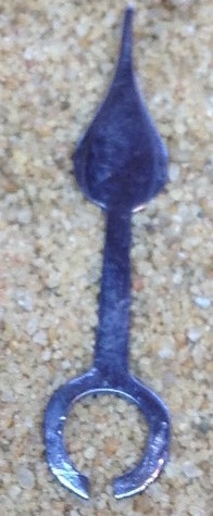
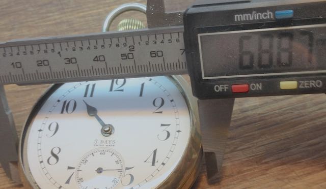
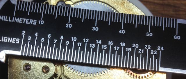
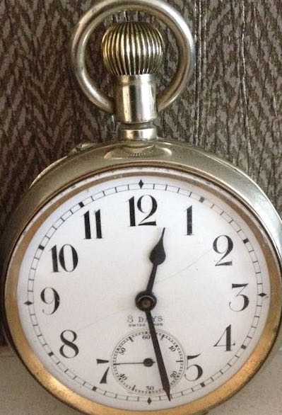
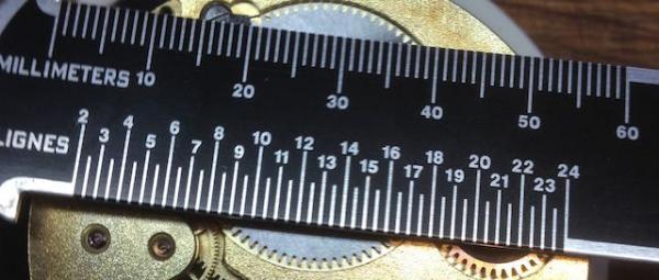
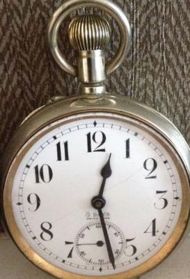
I was asked to look at this very large pocket watch because although serviced a few years ago had stopped running. It was immediately apparent to me why it was not running. Apart from the glass falling out when I opened the front of the case the hour hand was so badly bent it had hooked itself around the subsidiary seconds hand. Once unhooked the watch ran but now the hour hand was free wheeling. On closer inspection the hour hand was really badly bent, pitted and the part that attaches it to the cannon pinion (which was also usual as it has a horse shoe shape) had been bent too wide. Both hands were also had a fair amount of rust. I straightened and re-shaped as best as possible and polished them with diamantine powder. Then I had to re-blue the hands. To get a nice even blue I found really difficult because I could not remove all of the pitting & could not get the hands perfectly straight. Also being aware if I broke anything it would be very difficult to find replacement parts so I did the best job possible. I found the best results was by putting the hands in a tray of sand and heating over the gas stove and once blued dropping them into some machine oil. Not a perfect even finish but still I think a fair result. The reason the hands were so badly damaged is because the customer was opening the front of the watch and moving the hands with his finger. I have explained to the guy that this is a pin set watch & the pin in the top of the watch should be depressed to adjust. I have done a lot of research but with no ID marks I could not find the identity of this watch or in fact any pocket watch that was 25 ligne. Perhaps Willfly might have an idea. The customer said it was his grandfathers who worked on the railway so it might be a railway watch. I have attached a few pics (sorry about the quality) for your inspection. First Attempted at straightening & polishing First attempt at Blueing Job Done (I think still on test)


 1 point
 -
What a pity, it was going so very well. If nothing else, you have let folk what can be achieved regarding cleaning, most would have binned it straight away.1 point
-
This is a very nice military watch by Jaeger-Lecoultre - an excellent and much sought after model - purchased by the British Government in the late 1930 or early 1940s for use by military personnel in World War 2. "G.S.T.P" stands for General Staff Trade Pattern - meaning that it was an official procurement by the War Department. The 262533 is a serial stock number, but I can't say what the "XX" is. Some people believe that the T.P. in G.S.T.P. stand for Time Piece, but Trade Pattern makes more sense as other military equipment also had the G.S.T.P marking. If the watch is in good working order, it would probably fetch between £200-£300 at auction at current rates.1 point
-
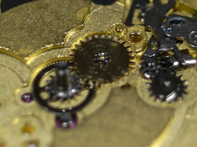
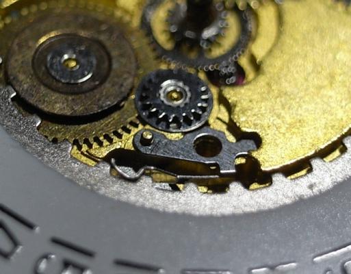
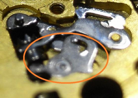
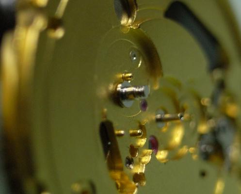
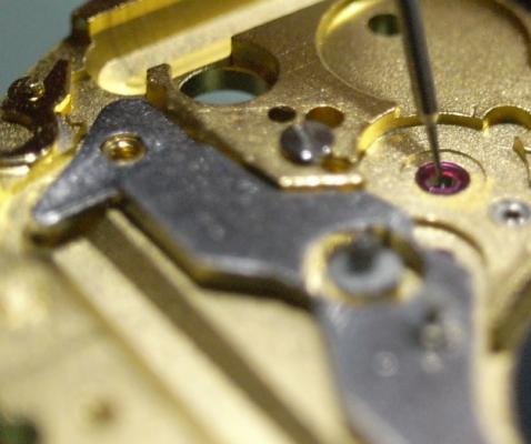
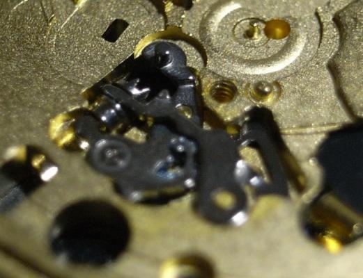
Kind of thinking out loud here as I don't know if my logic is sound..... If the bottom hole jewel, which would be uppermost in DU position, were too big for the pivot, either due to excessive wear (of either jewel,or pivot, or both) or because the original jewel had at some time been replaced with one too big, is it possible that instead of spinning smoothly in the jewel, the pivot might develop a tendency to "riddle" in the jewel hole causing the balance to stop? In DD position this would be prevented by the contact between the end of the pivot and the cap jewel, and in the vertical positions the pivot would lay on one side of the hole jewel, damping any tendency to vibrate so things would run smoothly. What is the side shake like?1 point
-
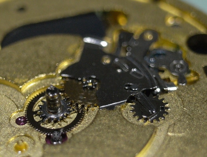
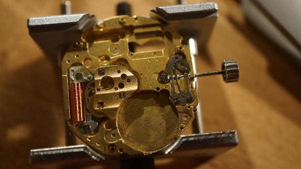
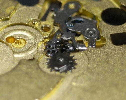
Don't do this :) . A really hard job getting all the gears in place . But now it's there ! First side finished .Geartrain running smooth . Haven't measured the coil yet
 1 point
 -
A way to do it would be to buy a Rolex style crystal (without the date magnifier) that is a good fit over the lip on the back. That way you'll have a cheap display back. :)1 point
-
Hi Anil and Pete, Not that I'm disagreeing with you Anil, but ...I would put in my two cents, older Seiko automatics can't be winded with the crown therefore Anil's response. Newer movements like the 4R36 not only can be winded through the crown but has a hacking seconds! Just replaced one in my old Seiko 5 case...beautiful substitution, works like a charm! Cheers, Bob PS: "Ingersoll Watches -- been around since 1892, founded by Charles and Robert Ingersoll in the United States. With their company, they had one of the earliest (if not the earliest) automated assembly line for watch manufacture. Those watches weren’t just some cheaply thrown together piece of junk. They developed a reputation for quality and precision; with the one dollar asking price (which was a days wage at the time), it quickly became known as “The Dollar Watch”. These watches were so popular, that even Teddy Roosevelt (US president), while travelling in Africa, was referred to as being from the country of the dollar watch. While they’re no longer an American company (they were purchased in the late 80s by British company Zeon), they embrace the history and lineage of the company, and as a result, they have an extremely impressive catalog (quite literally – it’s the largest watch catalog for a single company ... ever seen). Oh, and included in that family of watches? The Mickey Mouse watch – Ingersoll was actually the first company to produce one back in 1933. While we don’t have any of their current Disney watches for review (yet), we do have ones from their other lines slated for review, including Ingersoll, Swiss Eagle, and Original Penguin." From "the wristwatch review" @Pete, Apparently your watch has an Asian (probably Chinese from researching on line) movement which make me think it will only wind clockwise...one direction.1 point
-
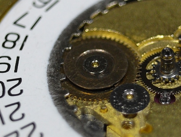
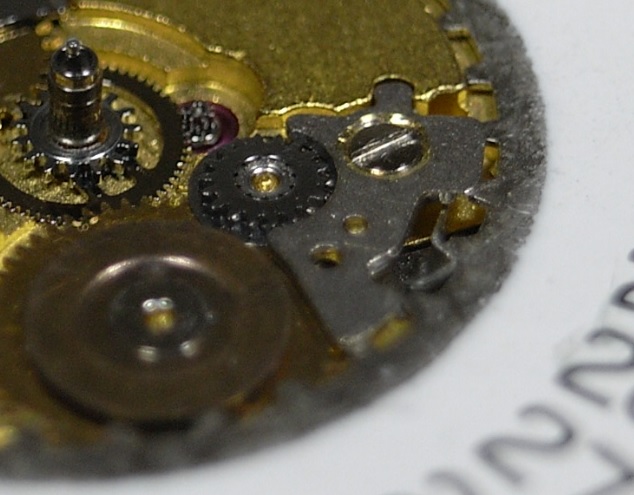
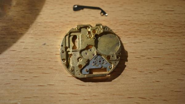
Thanks for the nice iilustration . This is how the movement looks after 4 baking soda runs and a nafta clean .
 1 point
 -
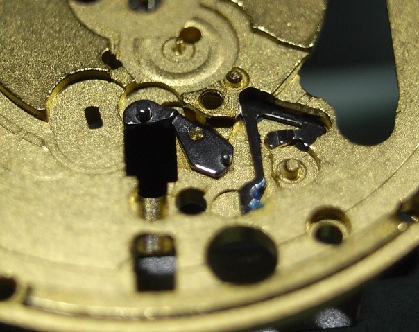
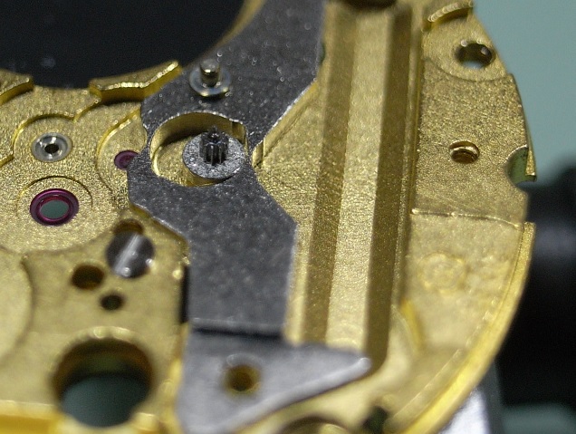
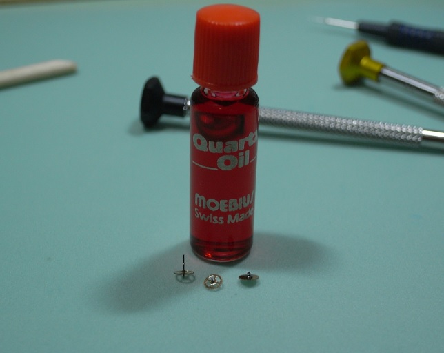
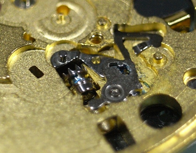
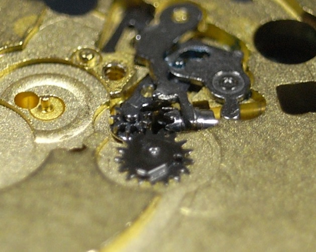
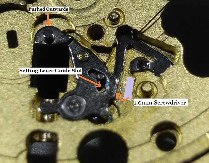
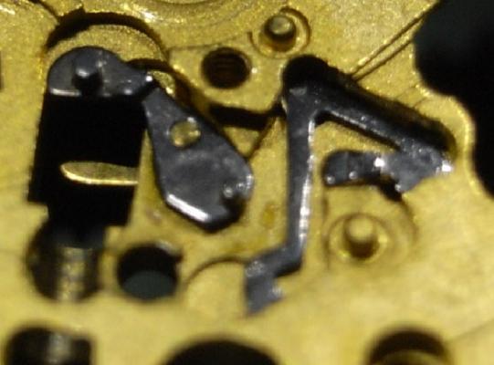
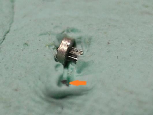
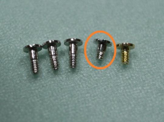
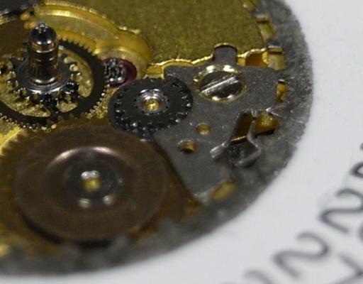
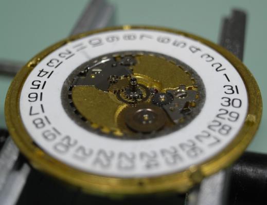
Assembly I have made the assembly walkthrough much more detailed, as putting things back together is always more tricky than pulling them apart :) Firstly install the Setting Lever Jumper and the Double Corrector Operating Lever. D5 on the Corrector Lever Pivot 9501 on the Setting Jumper To install the Setting Lever, first move the Double Corrector Operating Lever to it's most outward position, then push the Setting Lever 1/3 of the way down it's pivot, next place a 1.00mm screwdriver as shown below, and turn it clockwise. This will push the Setting Lever Jumper over to the other side of the pin on the underneath of the Setting Lever. Then push the Setting Lever home, making sure that the pin on the Double Corrector Operating Lever locates inside it's guide slot on the Setting Lever. I know this sounds a little complicated; but once you study the Keyless Work, you will understand the procedure I've explained here. Just take your time, and read through this procedure whilst looking at your work a couple of times until you are sure you've got it. Please Note: If you use a larger size of screwdriver be careful you don't push it too far over and bend the jumper ... using a 1.00mm driver is the correct size and will avoid this possibility. 9501 on the Setting Lever pivot 9501 in the guide for the Corrector Lever pin Flip the movement over and place the Setting Lever Spring Clip as shown below Then with a pair of tweezers push down on both sides of the clip and with a piece of Pegwood push it inwards so it locks in. Next install the Rotor, and you'll find due to it being magnetized, it will stick to the Stator. DO NOT try and locate it in it's jewel, as it will just pop out and stick to the Stator again, and this can be very frustrating ... but I have a little trick that will cure this :) Place one of the screws on the opposite side of the Main Plate, behind where the Rotor is located, and you'll see it will be attracted to the Rotor (as seen below). This little screw will pull the Rotor downwards and stop it being pulled over by the Stator, so you now can locate it in it's jewel. Don't forget to remove and demagnetize the screw once you've completed installing the gear train. There is a LOT of discussion on oiling quartz gear trains. The ETA Service Manual says to use Moebius 9014 on this particular movement; but I prefer Moebius Quartz Oil, as it can be used on both metal and plastic gears without concern ... why have 2 oils when 1 will suffice for both applications. Others say, don't oil the gear train at all, as it just adds load to the movement and makes it draw more current. Personally, I'd rather change a battery a little earlier than change out a worn out movement ... you choose which is cheaper. When oiling any quartz gear train, we only apply about half of what you'd use on a mechanical movement ... it's called Ghost Oiling. That being said, ghost oil the jewel for the Third Wheel with Quartz Oil as shown below. Ghost Oil the upper part of the Second Wheel with Quartz Oil as shown below Fit the Gear Train into the Main Plate. Place the Gear Train Bridge over the wheels, locate the pivots carefully until all are freely spinning, and tighten down the bridge. Remember once the screw makes contact with the bridge, STOP, and recheck the free spinning of the train before completely tightening the screw. Once the Bridge is secure, place the Stop Lever and Switch back onto it's pivot. D5 for Stop Lever and Switch pivot Quartz Oil for all Gear Train pivots (remember to oil both sides) Next install the Battery Isolator, making sure to push the tab into it's slot as shown below. Then install the Isolator Block Next we need to short out the screws for the IC Board. You'll see there is a Gold Screw, this is for the Coil Protector, and then there are three screws of the same length, and one shorter one. The shorter screw must be place into it's correct hole. Locate the IC Board onto the movement. Before I screw the IC Board down, I always fit the Coil Protector first. This helps avoid any damage if you accidently slip off a screw head. Remember to use the Gold Screw. Next place all the rest of the screws into their holes, noting the position where the short screw is to be located. This side of the movement is now complete. Time to flip it over and complete the Keyless Work, Motion Work and Calendar Work. Place the Sliding Pinion into it's position. Please Note this is a spare movement I'm using here, and I don't have a stem. If you have a stem, now is the time to install it. 9501 in the grove for the yoke on the Sliding Pinion 9501 on the stem Place the Yoke into position D5 on Yoke Pivot Install the Setting Wheel and Date Corrector D5 on Setting Wheel pivot D5 on Date Corrector slot Next is lubricating the Cannon Pinion. This is one step that MUST be done correctly, otherwise too much friction will occur and you'll damage the Setting Wheel in short order. 9501 Canon Pinion fiction points Place the Canon Pinion and then the Minute Wheel D5 Minute Wheel pivot D5 Ghost Oil the Canon Pinion Tube Attach the Motion Work Bridge and secure it down. Place the Date Ring onto the movement, and then slide the Date Indicator Driving Wheel into place, so the teeth of the Date Wheel are inside the Driving Wheel. Then install the Intermediate Date Wheel. D5 Date Indicator Driving Wheel pivot D5 Intermediate Date Wheel pivot Lubricate the foot of the Date Jumper Spring as shown below 9501 Date Jumper Spring foot Place the Date Jumper Spring into position on the movement Place the Date Jumper Maintaining Plate and secure it. Check the date and time setting, making sure the quick date works smoothly. Check the feel of the Motion Work, making sure there is not too much or too little friction from the Canon Pinion. Your movement is now completely serviced, all that's left to do is fit Hour Wheel, Dial and Hands :woohoo-jumping-smiley-emoticon: It's good for another 100,000 miles or 5 years ... whichever comes first ^_^ I hope this walkthrough both helps and encourages you with servicing your 955/6 ETA Movement


 1 point
 -
Magical Clocks are fun to watch and figure out. I came across an unusual clock at the Cabin Fever Expo in York, Pennsylvania. I setup a table to sell my dvd's and in the distance I saw what I thought was a acrylic clock but on closer examination it was a skeleton clock with magnetic wheels. Advance the video to about 3.5 minutes in http://youtu.be/watch?v=qtUkPbB3RwE Video was taken after the show was over which explains the lack of people. Several thousand modelers swamp the show everyday.1 point