

-
Recently Browsing
- No registered users viewing this page.
-
Topics
-
-
Posts
-
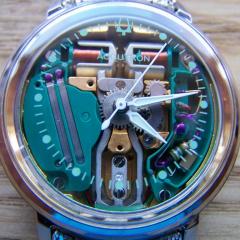
 Nice! I have lately been buying up a handful of Arnex pieces on eBay because it is often obvious even without photos that they house a fine Unitas 6498. And many of the 1970s cases and "old timey themed" dials are irredeemably ugly so they are a cheap way to pickup great movements to power custom wristwatch projects. All of the ones I've bought were in like new condition, barely used assuming they were bought as graduation or retirement gifts in the 70s or 80s.
 -

By ManSkirtBrew · Posted
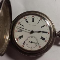
Walked by my local jeweler today and asked if I could dig around in his old watch case, and picked this guy up (along with a cool vintage compass and a Seiko kinetic5M62). My girlfriend's son asked if he could borrow one of my pocket watches for prom, so I thought if I can get this guy running it'd be a nice prom gift. Non-running. Felt like the balance was overbanked, but it turns out the train was jammed solid. Looks like it was just dried lubricant gluing the 3rd wheel in place, because it's clean as a whistle otherwise. Parts are in the ultrasonic right now. -
 Neverenoughwatches. I did read your experience with the basket. I did try to file mine to true it up..but I couldn't find the sweet spot. I figured I would just bite the bullet and get the Elma components. Thanks Randy
 -

By HectorLooi · Posted
My mentor has been using one of the Chinese clones for several years. Seems to work very well. Just put the object you wish to demagnetize in the centre of the cross and press the button. One word of caution though, the quality and QC of Chinese clones can vary a lot. You'll never know whether you got a gem or a lemon. -
By KarlvonKoln · Posted
You could also use a very fine artist's brush to brush between the coils. If you get a size 00 or even 000 that should be small enough for convenience, and with bristles so fine that they are incapable of damaging the hairspring. Get a good one though, like Windsor-Newton or similar. I have never had a Windsor-Newton brush shed on my art or other work. You want a soft brush that will not shed.
-


Recommended Posts