Jump to content

Recommended Posts

Posted
  On 12/17/2024 at 8:33 AM, AndyGSi said:

Yes it does.

Expand  

Question: can a chrome plating be regarded isolating?

But let the pusher be plastic, the device has even more safety issues, I found on 2nd look.

Some info on safety classes.

Buyers of such devices from china must be aware that they are regarded legally the importer (just like Cousins and others) - with all legal obligations. and liability.

Posted

All this debate about the switch, and I'm wondering about the bolts that hold the coil in place. I think it's a stretch to declare it unsafe on the basis of a single photograph, but equally it's unclear from a single photo whether it meets the European/Australian requirements for a Class II or Double-Insulated appliance. I don't think the switch is a problem if it's switching low voltage. It doesn't look like the mains wires are long enough to touch the body of the switch even if they were to come adrift, and if they touch somewhere else they shouldn't the insulation of the switch will still protect the metal push-button so a single failure would not lead to dangerous voltages being exposed. The bolts holding the coil should be insulated from the body of the coil and its not clear from the photo whether they are. All up, though, you're far more likely to get a shock from your washing machine or dish washer than from this device.

More importantly, did you demagnetise your balance? How does it look now? I recently had a balance where the two outer coils were touching. I demagnetised and they immediately sprang apart to perfect concentricity.

  • Like 1
Posted

Most demagnetizer circuits I've seen convert mains AC to DC and charge up a large value capacitor. It may or may not have a voltage doubler.

The switch disconnects the capacitor from the mains and connects the capacitor to the coil. The inductor/capacitor circuit ossilates and decays naturally.

So, the switch is definitely connected to high voltage.

I don't think there is any low voltage circuitry in this contraption. 

Where is Prof @LittleWatchShop when we need him? I think he worked on a few of these demagnetizers before.

Posted
  On 12/18/2024 at 4:03 AM, HectorLooi said:

So, the switch is definitely connected to high voltage.

I don't think there is any low voltage circuitry in this contraption. 

Expand  

The button should energise the relay and led which means there must be some sort of resistive or capacitive dropper.

  • Like 1
Posted

Anyone concerned about the electrical safety of this or any other tool might prefer to operate it via an RCD (Residual Current Device) safety switch.  These will detect any leakage to ground from the active wire of 30 mA or more,  and immediately shut off the voltage.

In fact,  since everything on my bench runs from a single outlet,  I plan to buy one myself.

There are many kinds but here is a link to one example. https://www.bunnings.com.au/arlec-single-outlet-safety-switch_p7050029

Obligatory disclaimer:  I am not an electrical engineer and this is not professional advice.


  • Like 1
Posted (edited)
  On 12/18/2024 at 4:03 AM, HectorLooi said:

Most demagnetizer circuits I've seen convert mains AC to DC and charge up a large value capacitor. It may or may not have a voltage doubler.

The switch disconnects the capacitor from the mains and connects the capacitor to the coil. The inductor/capacitor circuit ossilates and decays naturally.

So, the switch is definitely connected to high voltage.

I don't think there is any low voltage circuitry in this contraption. 

Where is Prof @LittleWatchShop when we need him? I think he worked on a few of these demagnetizers before.

Expand  

I read the whole thread. Here are some thoughts.

Most (if not all) of the good demagnetizers operate on the same principle using the Villard cascade voltage multiplier.  I have serviced three or four--all branded "Vigor."  In every case the 4uF capacitor had died.  Will explain later. Comments below are all based on the Vigor.

- there is no low voltage anywhere in the circuit

- the push button is plastic mounted in a metal housing but I believe the metal is isolated (I will check later).

- the push button is connected to the highest voltage in the circuit.

- the transformer is not wired as a transformer and is simply used as a BFI (big freaking inductor).

- the Vigor is not powered using a three-wire cord with the third wire being earth ground.  I have no expertise in the regulatory stuff associated with "double insulated" etc. (I am a semiconductor guy...most of my life has been spent at 10V and below!!).  But, I don't think the Vigor meets the double-insulated requirements--my guess.

The units I have serviced, were completely rebuilt except for the inductor, switch, and neon bulb.  In all cases the 4uF cap had gone bad.  The reason is that the unit is continuously plugged and and you have the full rated voltage across the cap for the entire time.  Stress eventually wins the day.  Therefore, for all my rebuilds, I put an inline switch on the power cord.

image.thumb.png.acc2fdc708ba01f4f10a3c4403474da6.png


image.png.b9814ba6e7b7985ffe974181b53b45c7.png

image.png.aa4486e109cecd1149910393bf6fe20b.png

Edited by LittleWatchShop
  • Like 3
  • Thanks 2
Posted
  On 12/18/2024 at 8:29 AM, ChrisInOz said:

Anyone concerned about the electrical safety of this or any other tool might prefer to operate it via an RCD (Residual Current Device) safety switch.  These will detect any leakage to ground from the active wire of 30 mA or more,  and immediately shut off the voltage.

In fact,  since everything on my bench runs from a single outlet,  I plan to buy one myself.

There are many kinds but here is a link to one example. https://www.bunnings.com.au/arlec-single-outlet-safety-switch_p7050029

Obligatory disclaimer:  I am not an electrical engineer and this is not professional advice.


Expand  

All modern domestic wiring  installations in the last 20 years in the UK will have RCD protection. Still a lot of unprotected homes though mine included in some earlier circuits of my house. I run everything in my watchroom from 2 good quality plug-in RCD units, nice and close to all the devices and appliances I have in there. For the sake of 50 quid for these or replacing two sockets for two passive RCD sockets, reduces any potential electrical hazards .

  On 12/18/2024 at 11:24 AM, LittleWatchShop said:

I read the whole thread. Here are some thoughts.

Most (if not all) of the good demagnetizers operate on the same principle using the Villard cascade voltage multiplier.  I have serviced three or four--all branded "Vigor."  In every case the 4uF capacitor had died.  Will explain later. Comments below are all based on the Vigor.

- there is no low voltage anywhere in the circuit

- the push button is plastic mounted in a metal housing but I believe the metal is isolated (I will check later).

- the push button is connected to the highest voltage in the circuit.

- the transformer is not wired as a transformer and is simply used as a BFI (big freaking inductor).

- the Vigor is not powered using a three-wire cord with the third wire being earth ground.  I have no expertise in the regulatory stuff associated with "double insulated" etc. (I am a semiconductor guy...most of my life has been spent at 10V and below!!).  But, I don't think the Vigor meets the double-insulated requirements--my guess.

The units I have serviced, were completely rebuilt except for the inductor, switch, and neon bulb.  In all cases the 4uF cap had gone bad.  The reason is that the unit is continuously plugged and and you have the full rated voltage across the cap for the entire time.  Stress eventually wins the day.  Therefore, for all my rebuilds, I put an inline switch on the power cord.

image.thumb.png.acc2fdc708ba01f4f10a3c4403474da6.png


image.png.b9814ba6e7b7985ffe974181b53b45c7.png

image.png.aa4486e109cecd1149910393bf6fe20b.png

Expand  

Good tip👍about the in-line switch, I recently did just this with a permanently plugged in transformer for the power supply and speed adjuster for a dc motor that runs my rotary washer. 

  • Like 3
Posted (edited)
  On 12/17/2024 at 8:28 AM, Neverenoughwatches said:

I think everyone has assumed it is Andy unless they know for sure, but it does look like steel, the casing at least. Does plastic come in a steel/chrome colour 🤔.......👍.......😅

Screenshot_20241217-082441_Samsung Internet.jpg

Expand  

Just checked. The switch is metal.

Also I haven’t demagnetised the NH35 yet as I lost one of the balance end stones and my replacement only came in today. So I’ll clean it, oil it and put it back in. Then I’ll demag and see how the amplitude responds.

Edited by neevo
Posted (edited)
  On 12/19/2024 at 8:42 AM, neevo said:

Just checked. The switch is metal.

Also I haven’t demagnetised the NH35 yet as I lost one of the balance end stones and my replacement only came in today. So I’ll clean it, oil it and put it back in. Then I’ll demag and see how the amplitude responds.

Expand  

Do you have any sort of meter to confirm the voltages.

Edit

If not can you confirm what it says on what I expect is a relay in the bottom left corner of the PCB.

Edited by AndyGSi
Posted
  On 12/19/2024 at 9:48 AM, AndyGSi said:

Do you have any sort of meter to confirm the voltages.

Expand  

There are two big black capacitors on the circuit board in the picture posted by @neevo,  and the one at the back has markings for 220 nanoFarads at 630 volts.  I can't see the markings for the huge black capacitor on the right hand side of the case,  but I suspect it will be similar to the 4 microFarad one from @LittleWatchShop's circuit diagram.  With diodes in circuit, it could easily have 350 volts on it,  and judging by its size,  it would pack a hell of a punch.   I, personally,  wouldn't risk poking at it even with the mains power disconnected.  You definitely don't want to be fooling around with those sorts of voltages.

I think,  when I buy one of these demagnetisers, I might keep a plastic rod handy for pressing the button,  just in case.

Posted

I had a few more tools and parts come in recently and this morning I was able to put them to use.

Using my new titanium tweezers I set about oiling the new end stone for the chaton and putting it back on the balance. It took me about 20 goes to get the balance back in with the impulse jewel in the right way. I get the concept but just couldn’t execute it properly. Patience and taking it back out and trying again was the trick and there is something magical about it kicking in to gear on its own!

Heres where I think I’m running in to a new issue. I dont have a timegrapher. Instead I bought an app for my phone and trying to use an old pair of headphone. But I’m getting really erratic results on the app.

It’s showing the amplitude at 315 degrees and it’s clearly better visually on the balance. However the app is really struggling to lock on to the movement so I don’t really trust the readings yet.

For example the beat error is 4-5ms and the rate is all over the place.

Then I realised I forgot to demagnetise. So I popped it on my demagnetiser and retested.

  • Like 2
Posted
  On 12/22/2024 at 11:12 PM, neevo said:

It’s showing the amplitude at 315 degrees and it’s clearly better visually on the balance. However the app is really struggling to lock on to the movement so I don’t really trust the readings yet.

Expand  

Does the app take into consideration the lift angle as 315 is high.

Posted
  On 12/22/2024 at 11:28 PM, AndyGSi said:

Does the app take into consideration the lift angle as 315 is high.

Expand  

I’m not sure. I think the main issue I’m having with the app is that it’s not really picking up a strong enough signal from the movement. Only 1 out of 5 bars lights up. Maybe the microphone on the headphone is not good enough to pick up the sound.

IMG_1379.thumb.png.327fde423c6fbac4301e4355ab3ed8ea.png

Join the conversation

You can post now and register later. If you have an account, sign in now to post with your account.
Note: Your post will require moderator approval before it will be visible.

Guest
Reply to this topic...

×   Pasted as rich text.   Restore formatting

  Only 75 emoji are allowed.

×   Your link has been automatically embedded.   Display as a link instead

×   Your previous content has been restored.   Clear editor

×   You cannot paste images directly. Upload or insert images from URL.


  • Recently Browsing

    • No registered users viewing this page.
  • Topics

  • Posts

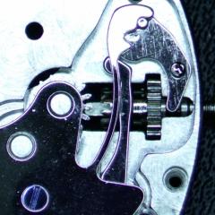
    • Yes, the specific old tools do exist, but may be having one is not needed as they are not cheap, and also You will be able to do without it well enough. My advice will be to use regular depthing tool and adjust it for the exact distance between pallet fork and escape wheel bearings from the watch. Then remove the shellac from the pallet that now doesn't pass the ew teeth and move this pallet in. Then put the pallet fork and ew on the depthing tool and check how they lock. They should not lock when the pallet is in, but You will little by little move the pallet out and locking will appear. Then move just an idea out for reliable work and apply shellac, then check if things are still the same. You have to observe where the teeth fall on the pallets - it must be just a little below the edge between impulse and rest planes. Then You must check how everything behaves in the movement This Potence tool is so ingenious, but actually, the traditional way to do the things is much more simple. Arrange the parts not on the pillar plate, but on the cover plate. Only the central wheel will remain on the pillar plate, secured by the cannon pinion.
    • There is a tool that was made for setting up and adjusting escapements of full plate watches.  There were two styles, the picture below shows both of them.  The lower tool held a movement plate and the vertical pointed rods were adjusted to hold the unsupported pivots of the lever and escape wheel.  There was also a version of this tool that had 3 adjustable safety centres so that the balance pivot could be supported by the tool :  The other version I’m aware of is the Boynton’s Escapement Matching and Examining Tool came as a set of two or three clamps that gripped the watch plate and held the safety centres for the pivots : These do turn up on eBay from time to time.  For some escapement work, you can set up the parts in a regular depthing tool, with the centres set according to the distance between the corresponding pivot holes on the movement.  I hope this helps, Mark
    • Once you are aware of the problem, you can adjust as necessary. I have a couple of the Omega 10xx, and they are not my favourites. They seem a bit flimsy and not as solid as previous generation Omega. But I think that's true of a lot of movements from the 70-80s. For me, the 50-60s is the peak in watch movements, where the design criteria was quality, not saving the last penny.
    • Thanks for this post MikePilk, I just came across a similar problem with an Omega 1022.  The problem I had was the seconds pinion spring was bent out of shape and did not even engage with the wheel properly, so the seconds hand was not moving at all. (no power loss though :) I removed the automatic module so I could access the spring and work on it. Once I bent it back close to the right shape, I experienced the same problem you reported about power loss.  Many tweaks later, and the seconds hand is moving properly again, with amplitude back to good numbers again. Cheers
×
×
  • Create New...