Jump to content

Recommended Posts

Posted (edited)

Ok. So a bit more detailed inspection of the clock today has uncovered this disappointing issue.

The clock has an axial crack on the first 'roll' of the base. It is not bad, but I don't want it to get worse. About 10~12mm long. Who am I kidding? It's crack in a clock base! Of course it's bad.

So I have been sitting here formulating an idea for how to address the crack. Let me know how this sounds please.

1) Strip clock down so just have base on it's own. (obvious)

2) Remove lacquer from base using a paint stripper so as to not introduce scratching to the base brass surfaces.

3) Get a G clamp the will fit across the base diameter and work on a clamping method that can be applied quickly. The reason for quickly will be explained below.

4) Using a Dremel with appropriate bit installed, grind a groove on the underside of the base along the crack.

5) Preheat oven to 190 deg C (melting point of my 60% tin, 40% lead solder) and put base in oven in flat tray.

6) Once the base has heated up, remove from oven, apply solder to fill groove that has previously been made. Use soldering iron as required to assist.

7) Once solder has filled groove an hopefully has entered the crack as well, apply G clamp to pull crack together and inline along the 'roll' onethe base.

8 ) Allow to cool to room temperature. Finish as required.

Reasoning.

Heating with a torch to be able to braze the crack would be too localised and could potentially crack the base more. Even with preheating.

The groove is to give the solder more adhering strength across the crack  for the length of the crack.

I do not believe that something like a cyanoacrylate glue would be a viable option.

The rest of the clock, including everything in the movement is that clean, I think I would add dirt cleaning it.

I would hope that I would be able to end up with a near invisible repair.

If anyone else has any other ideas or proven repair methods, it would be greatly appreciated.


Edited by Michael1962
Posted

Soft solder is not very strong & in a crack like that it would be little more than cosmetic.

I would suggest soldering a thin brass "patch" or strip brace across the crack on the underside, to add structural strength.

I would not try clamping the crack closed; that will only introduce further stresses as everything cools. If the crack is at the lower edge and is due to damage (such as someone picking it up by the edge), some very careful tapping with a soft hammer to bring the outer edges down & close the crack may help?

If you use solder paste in the joints and line up the parts carefully before heating, using spring clips to hold the strip or patch on place, you can heat it until the solder flows then allow it to cool slowly again. I think that should add the least stress.


Posted

All youngsters,  80 plus medical problems after Covid but still operating.. two French clocks done a Viennese regulator on the bench a barometer to do and a schatz 400 day,   So  quite busy.

I am inclined to agree wirh Rob, I have come across bases repaired the same way and when polished up the crack is almost invisible.

  • Like 1
Posted (edited)

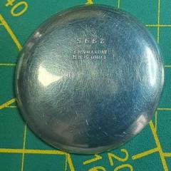
As requested @oldhippy Crack can just be seen in pretty much the middle of the photo.

I wish I knew how these things happen. I am surprised that the brass cracks and doesn't deform.

IMG_2169.thumb.JPG.655346f5daf3f6cde6ce7a2640646753.JPG

Edited by Michael1962
Posted

Hi Michael,  these bases are made from sheet brass spun and formed some are pressed out. Any forming off metal creates tension within the metal, it’s probably a stress crack  and once repaired as suggested should be invisible.  It’s well tarnished and looks like the varnish/ lacquer has aged. Should clean up ok


Posted

Are you suggesting a cyanoacrylate glue @oldhippy?

I will have a look once I get the clock apart to see how difficult it is to get the base circumference in line. That should let me know what will be the best way to repair it to hide the flaw.

Posted

That is the trouble with thin spun brass they get stress cracks DON’T try soldering  it will make matters worse, ( ask me how I know ) but as others have said glue a thin brass strip across it , it’s a shame where you are because I probably have one.

Dell

Posted
7 hours ago, RichardHarris123 said:

Brass can be welded, assuming you had the equipment or knew someone with experience, would it be a viable option 

Brass can be brazed or silver soldered but being spun and very thin there is a very high risk of distortion .

  • Like 1
Posted

Would low melting point (70'C) solder for white metal be better than glue, to fix a reinforcing strip? That works very well on brass, I've used it quite a bit in modelmaking.

Just be sure to clean everything thoroughly and use acid flux.


  • 4 weeks later...
Posted

If it's a stress crack,  might it be appropriate to simply stop-drill it to prevent it spreading further?  I'm thinking perhaps an 0.5 mm drill bit at the top of the crack to relieve the stress point and prevent the crack increasing in size beyond that point.

Posted
5 hours ago, Michael1962 said:

That's not a bad idea. Then plug the hole like a bushing. Should be able to stop it and hopefully the plug would be next to invisible.

I'll have a think.

At half a millimetre diameter,  I would think even the hole itself might be next to invisible.

  • 2 weeks later...

Join the conversation

You can post now and register later. If you have an account, sign in now to post with your account.
Note: Your post will require moderator approval before it will be visible.

Guest
Reply to this topic...

×   Pasted as rich text.   Restore formatting

  Only 75 emoji are allowed.

×   Your link has been automatically embedded.   Display as a link instead

×   Your previous content has been restored.   Clear editor

×   You cannot paste images directly. Upload or insert images from URL.

  • Recently Browsing

    • No registered users viewing this page.
  • Topics

  • Posts

    • I believe @nickelsilver has a setup like that.
    • I posted pictures earlier in this thread. My lathe and mill are two separate instruments. I think I have seen examples of putting a milling head on a lathe bed...but not certain.
    • Timex Camper, September 1994, new to me. Strap is an old perlon with "Germany" in script etched into the resin on the tail end. Not Horlon or Eulit I believe. History unknown, running strong, losing less than a minute a day. Goals for this: Wear it a ton! Buy crystal lift, clean out the gunk around the ring and under the crystal Eventually swap into a stainless steel case. I've seen a member who has swapped a Timex mechanical movement into the Timex J.Crew quartz field watch case.
    • One of the problems we would have with a watchmaker's lathe is they were made over considerable span of time and manufacturing in the early days probably wasn't as good as it was today. Then if you look at the older catalogs typically it was just the head a few collets and something to rest graver on. So basically a basic lathe with over time things acquired but acquired things may or may not fit. Order today you purchase a used lathe that all kinds of nifty bits and pieces from a seller that acquired from? This would come back to that the basic watchmaker's lathe was used for basic watchmaking like turning things with a hand graver. Then limited indexing is fine because you can make things like stems Which don't need a whole bunch indexing   In the link above the word vector is mentioned and at the link below you can purchase one. Then of course you're going to need the motor that's a little bit extra for the price. https://www.hswalsh.com/product/lathe-vector-watchmakers-48-collets-hl11. That you're going to need some bonus parts like these found this picture online show the classic way of classic gear cutting.   The lathe could have a much bigger indexing disk but it has to be mounted close to the edge. Otherwise you're going to have a whole bunch of smaller disks like this which I think has notches rather than holes. Then as wonderful as these pictures look actually cutting a gear with this is not entirely fun. Look at all is belts all pulling on things and this is a watchmaker's lathe lightweight with lots of bits and pieces attached. It would make more sense if you actually cut a gear with something like this and it tends to be it's not really the best way to do it looks nice on paper but it is not the best way to go. Reality for cutting watch parts would be a bigger machine is much better. Than getting rid of all those belts and pulleys also good. Here is an interesting channel I would've liked of found a different video but this was nice and short if you look at his video as he uses a stepping motor and worm gear assembly for the indexing plate. In this particular video it gets attached to the lathe at about one minute and seven seconds and it looks like it's hiding looks like he has a Sherline. I do know he's had other stuff you'll just have to go through his videos to find it. Then at about one minute and 22 seconds you find out if you set up things appropriately. It's always bad we end up with half a tooth at the very end. Then you will note big lathe yes he's getting a big gear but you could easily cut a watch gear with the setup. And it definitely way more stable than a watchmaker's lathe.         Oh here's a company they been in business since 1911 http://www.fwderbyshireinc.com/  
    • Hello and welcome from Leeds, England. 
×
×
  • Create New...