
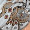
Regulating A Watch

-
Similar Content
-
-
Recently Browsing
- No registered users viewing this page.
-
Topics
-
-
Posts
-

By rjenkinsgb · Posted
Many would disagree: https://www.rohm.com/products/faq-search/faqId/234 https://uk.farnell.com/c/semiconductors-discretes/transistors/bipolar-transistors/pre-biased-digital-bipolar-transistors https://uk.rs-online.com/web/p/bipolar-transistors/8232832P?gb=s https://uk.rs-online.com/web/p/bipolar-transistors/0580240?gb=s (RS don't have a specific category, but over 1000 "digital transistor" items). -

By Hawaiikook808 · Posted
Thanks, ManSkirtBrew. I started looking for a setup like yours and ran across this. It was about half the price of the JKA Feintaster (depending on what auction you were in), and it's a Bergeon. I bought it because I thought the price was fair (eBay - Buy it now), and I'm a sucker for vintage tools. It also has a table, so it should be easy to use for measuring jewels. I wonder if the the contact points can be changed out. Bergeon seems to manufacture new tables and accessories for the contemporary dial version. What do you guys think of it? I'm sorry this post seems to have taken a detour. I'm new here so let me know if I should start a new topic. -

By nevenbekriev · Posted
This is a flying cutter, usual one. The cutter itself is shown in the pictures in the first message, it is made of broken tungsten carbide drill bit. I asure that all the angles of the cutter are as they should be. I have video - little older one - that I made when onse making the same kind of winding pinion for a Poljot 2200, which is even smaller than this one. It is not easy to see in the video, but the tool rest moves about 1mm towards the object in Y direction and then returns back untill cutter is rotating. Then the spindle is rotated one tooth ahead and everything repeated untill all teeth are cut. -
 After a bit further research could it possibly be an AS 970?
 -
 Latest project was a non-running ebay purchase with an FHF70 movement. I stripped and cleaned it, reassembled it, and got it running. So far so good, nothing damaged AFAIK. I was oiling the top jewel on the balance (the one in the cock) which was a slightly unusual shock setting. I removed the spring (3 leaves) which was part of a chaton holding the cap jewel. This left the hole jewel behind which I retrieved with rodico and then lost it. I was taking it off the rodico, very gently as I thought, with tweezers, and then it just disappeared. Fast forward a week, I got a donor movement, non-running, with the plan to just take the shock jewel that I’d lost. It was the same movement but had standard incabloc settings, and was steel rather than copper/brass. I changed the cock and balance complete and it ran, not very well. I switched the lower jewel setting, cleaned and oiled both jewels and the replacement balance. Without the pallet fork the balance swings very nicely with a puff of air. With the fork in place, balance out, it flicks side to side nicely with power in the mainspring. Put them together and it doesn’t run. The impulse jewel sits in the fork and it stops. Any suggestions how I proceed? In case you didn’t follow that I have 2 FHF70 movements, nothing broken as far as I can tell, but mixing up the balance wheels and jewel settings results in a non runner.
-


Recommended Posts