Jump to content

Weird Accutron 214 fault...


Recommended Posts

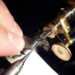
Recently I got an early 214 from 1963 that had a faulty coil. The coils on these are in two parts, a cell-coil and component coil, joined by three fine insulated single-core wires. The Cell coil had gone O/C due to water/battery leak rotting out the fine wires where they attach to the soldered binding-posts--Mainly because Bulova hadn't covered a small section of the wire with any protective varnish.

A replacement cell-coil was bought from the guy in Bulgaria and the  old one replaced on the coil assay.

Fitting to the movement, it didn't run. It would go for about 5-10 seconds after plucking the fork, but the hum would slowly die away. I assumed the resistor and capacitor were messing round --so replaced these in the component coil side. Still the same.

I checked the transistor--but it looked good in testing--I replaced it anyway, using a silicon device tacked in to test, altering the bias by changing the resistor from 3.9 meg to 2.2 meg, to accomodate the different bias requirements between a Silicon and the old Germanium device it was replacing  and tried again.

Exactly the same! I monitored the current using my home-made PSU, it would initially pin the meter and that would die away to 5uA, but the movement still not running and no hum either. Plucking the fork, it would run for 5-10 seconds, then the hum would die away, and no appreciable difference in current draw.

The clue was the constant current it was drawing after the initial pulse. It was perfectly clear when I dragged the Scope out and checked. The coil set was oscillating at 200 odd KHz! When the fork was plucked, the 360Hz was modulating the 200KHz. I guess a Long-wave radio could have picked it up if it was close by!

Fortunately,--Bulova had also run into this problem as well and on some coils added an extra capacitor to the component-coil to damp out the radio-frequency oscillations. A 0.01uF (1 Nanofarad, 1000pF) cap was installed at the point the wires from the cell-coil attach to the component-coil. Its placed between the leads of the drive coil (Red wire) and the feedback coil (Green wire).

Doing likewise with an 0805 1nF SMD cap cured the issue completely and the movement runs normally, even self-starting--with lots of wires and components hanging out of it! I just now need to rebuild it all properly and neatly into the component-coil recess--Which should be fun!.

I'm guessing that the inductance of certain Cell-coils must be just right to cause this oscillation so they added the extra cap on those causing troubles.


  • Like 1
Link to comment
Share on other sites

Ive made up a variable PSU just for the job,  from 0 to 2.5V. It uses a precision voltage regulator and a multi-turn pot, a 30uA Ammeter and a LED Voltmeter. It is supplied by a 7.2V battery of two 18650 rechargeable cells. Ive not tested how long it would supply a movement considering the batts supply the LED voltmeter as well, but I expect a couple of weeks  would be possible on a single charge. Most of the parts I had hanging round.

The voltmeter on it is for monitoring the supply sent to the movement, so apart from checking cells--its somewhat better than an Accutron tester, as its continuously variable supply from 0 to 2.5V, great for finding the Lowest Phase voltage at which a movement will run that I find Much more accurate for phasing than any other.

I do have an Accuton 700 test-set Somewhere, but havent seen it for a while, I must search it out, , the ammeter would be better than the cheapo thing I used in my tester!

Thanks to the web, Ive a few manuals on the Accutrons...


Edited by Alastair
Link to comment
Share on other sites

Ah--Sorry, These three-letter acronyms plague us!

PSU = Power-Supply-Unit, In this instance its more of a Test-Set I built specifically for Accutrons, being adjustable and monitored.

Ive located some better meters from China, allowing both the voltage and current to be digitally displayed--They were cheap, so Ive got them coming. According to the blurb in the add, the Ammeter will read to 0.01uA resolution 5 digit display 0-200uA FSD, be better than the cheapo 30uA 'Monachor' meter Ive got now, Just hope its internal resistance doesn't upset the design too much, its also adjustable so can compensate for the 100 odd K ohm the Voltmeter presents to the load read..

(If its not broke,--Pull it apart and re-design!)

Link to comment
Share on other sites


  • Recently Browsing

    • No registered users viewing this page.
  • Topics

  • Posts

    • My latest. Timex 2465. Replaced the crystal, caseback gasket and spring bars. All in less than $5US. Added a gray NATO strap I already had in stock.
    • I have some Gruen 510's in my donor pile if you need parts.
    • I've been intrigued by everyone's input here...so I decided to give this a shot. I bought the"typical" Pearl watch-machine basket and trays, for about $65. The trays are good,..the housing is a nightmare ! Thought it would take the mixer off my bench at anything above about 200rpm. The housing is cast of course,..and it's not "true" at all...so the harmonic vibration was insane. So,..I bit the bullet and bought the Elma housing and top. Not the baskets though, as the Pearl one's fit the Elma. Saved a bunch there. The basket and lid came to about $80 with shipping. The opening in the Elma top is 8mm, and the shaft that came with my stirrer is 6mm. I bought a piece of steel tube, 8mm O.D., and 6mm I.D. Cut off about an inch of the tube, and drove the rod into it. Gives a really snug fit.... Lightly champfered the leading edge of the 8mm section, then lightly tapped it into the top of the Elma lid. Spins like a dream now So... I have about $240 total into this including jars and steel mesh for the wave breakers   I'm pretty happy Best to you all   Randy
    • Still haven't gotten around to getting stems or screws, but I did make my first attempt at polishing a case. I just used a soft mop and rouge to reduce my odds of ruining them, and I think they came up pretty nice. Also gave the crystals a polish on the same wheel while I was at it. They were both very badly scratched up. The one on the left is fairly beat up, but it'll still make for a decent presentation.
    • You can try a rubber on that the sort for rubbing out a pencil.  
×
×
  • Create New...