Jump to content

Recommended Posts

Posted
1 hour ago, tomh207 said:

You also have another potential issue with head and tail stocks, in my research it would seem that for the American style lathes the head and tail stocks were bored as a pair

One of the problems we would have with a watchmaker's lathe is they were made over considerable span of time and manufacturing in the early days probably wasn't as good as it was today. Then if you look at the older catalogs typically it was just the head a few collets and something to rest graver on. So basically a basic lathe with over time things acquired but acquired things may or may not fit. Order today you purchase a used lathe that all kinds of nifty bits and pieces from a seller that acquired from?

1 hour ago, tomh207 said:

indexing is again not so straightforward for a watchmaker lathe, at least not as I have found so far. Often a lathe will come with basic indexing which is limited to 60 positions. The full index plates do come up at times for eywatering prices. It is very possible to do that electronically.

This would come back to that the basic watchmaker's lathe was used for basic watchmaking like turning things with a hand graver.

Then limited indexing is fine because you can make things like stems Which don't need a whole bunch indexing


1 hour ago, tomh207 said:

In the link above the word vector is mentioned and at the link below you can purchase one. Then of course you're going to need the motor that's a little bit extra for the price.

https://www.hswalsh.com/product/lathe-vector-watchmakers-48-collets-hl11.

That you're going to need some bonus parts like these found this picture online show the classic way of classic gear cutting.


image.png.b71fcc5c9ed61bfb8096bee1233e20d1.png

The lathe could have a much bigger indexing disk but it has to be mounted close to the edge. Otherwise you're going to have a whole bunch of smaller disks like this which I think has notches rather than holes.

Then as wonderful as these pictures look actually cutting a gear with this is not entirely fun. Look at all is belts all pulling on things and this is a watchmaker's lathe lightweight with lots of bits and pieces attached. It would make more sense if you actually cut a gear with something like this and it tends to be it's not really the best way to do it looks nice on paper but it is not the best way to go.

Reality for cutting watch parts would be a bigger machine is much better. Than getting rid of all those belts and pulleys also good.

Here is an interesting channel I would've liked of found a different video but this was nice and short if you look at his video as he uses a stepping motor and worm gear assembly for the indexing plate. In this particular video it gets attached to the lathe at about one minute and seven seconds and it looks like it's hiding looks like he has a Sherline. I do know he's had other stuff you'll just have to go through his videos to find it. Then at about one minute and 22 seconds you find out if you set up things appropriately. It's always bad we end up with half a tooth at the very end.

Then you will note big lathe yes he's getting a big gear but you could easily cut a watch gear with the setup. And it definitely way more stable than a watchmaker's lathe.


Oh here's a company they been in business since 1911

http://www.fwderbyshireinc.com/


  • Like 1
  • Thanks 1
Posted
3 hours ago, coreymsnow said:

For example, a Sherline mill would appear to be either a separate piece of gear or an attachment/expansion to their smaller lathe. When you say you have a WW lathe and a sherline mill, can you say exactly what devices you have?

I posted pictures earlier in this thread. My lathe and mill are two separate instruments. I think I have seen examples of putting a milling head on a lathe bed...but not certain.

  • Thanks 1
Posted (edited)

You might like to see the contraption that I made for indexing on my Chinese lathe.   This is a 4 inch rotary table with dividing plates that I attached to my lathe mandrel using a drawbar.  It is completely manually operated. No electronics or computer needed.  I have used it to make a 60 tooth clock wheel.

dividingHead800.jpg.78ee776741807d8e595b7b6f546ab580.jpg

I use a Sherline headstock on a vertical slide to drive the gear cutter.  The wheel blank is mounted on an aluminium "superglue arbor." This is the modern equivalent of a shellac chuck,  and allows the wheel to be centre bored, trued and the teeth cut in a single setup,  ensuring that concentricity is maintained.

cuttingTeeth800.jpg.b59e494d71e620b09445e02ee969310b.jpg


millSpindle800.thumb.jpg.4557a3150560cca7a2e3f59e4656132a.jpg

The finished wheel after crossing.

9-finishedWheel.thumb.jpg.5ca3b0d6fa1484ed0b6b95669e22d45f.jpg

I have not tried to make small watch parts on this lathe.  The runout on the mandrel bearings may be too high for that.  I won't know unless I try.


Edited by ChrisInOz
more info
  • Like 4
Posted (edited)
12 hours ago, caseback said:

I believe @nickelsilver has a setup like that.

I have a little milling attachment for my WW lathe, but very rarely use it and not for wheel and pinion cutting. For that I use a small Sixis 101 milling machine. I normally do direct dividing, but sometimes have to do an odd count and use the universal index which also fits on the Sixis.


Back in the day when I didn't have a mill, I would cut gearing on my Schaublin 102. It has a universal dividing attachment which fits the back of the spindle. Both it and the one for the Sixis are 60:1 ratio, and with the set of 4  index plates I can do almost any division. When I've had to do a strange high count prime number, I print a disc with the needed division and just place the plunger on the dot. Any position error is reduced by a factor of 60 so still plenty accurate.


The machines are a mess in the pics as I'm in the process of making a batch of barrels for a wristwatch 🙃.


This is the Sixis. The head can also be placed vertically, as can the dividing spindle.

20250426_120733.jpg


Dividing plates. The smaller ones fit another dividing spindle.

20250426_120853.jpg


Universal divider for the Sixis. I put it together with parts from an odd Sixis spindle that takes w20 collets, like the Schaublin 102, and a dividing attachment from a Schaublin mill.


20250426_120811.jpg


The dividing attachment for the 102. The gear fits in place of the handwheel at the back of the headstock.

20250426_120947.jpg


And the little milling attachment for the WW lathe. I just set it on the slide rest to illustrate the size, you can see from the dust on it it really doesn't get used much. I think only when I change bearing in the head, to kiss the collet head seat (grinding wheel still in the milling attachment).

20250426_120649.jpg

Edited by nickelsilver
  • Like 2
  • Thanks 2
Posted
On 4/24/2025 at 10:25 AM, coreymsnow said:

Thank you all for the tips and insights. I'm looking carefully at the Sherline lathes with a milling attachment. I need to figure out exactly what I'd need to get in terms of the base lathe and attachments to be able to fabricate basic parts and learn how to fabricate some of the less basic ones- like a cannon pinion.

Thank you again.

This guy (Minimachining) has a playlist of him setting up and using various attachments on his Sherline lathe.


On 4/24/2025 at 3:26 AM, LittleWatchShop said:

I own too many WW lathes, as well as two sherline lathes and a sherline mill with a cnc indexing rotary table. The majority of my experience is using the WW lathes to make staffs, screws, and stems.

Recently, I have been experimenting making a pinion on the mill using the indexing table. It works. So, if you want to cut wheels, get the Sherline mill and indexing table...imho

I know nothing about CNC machines but had a question about making screws. Watchguy.uk has a section on his website where it allows you to enter parameters for screws and wheels and then 'generate code'. Is it as simple as that sounds, can you 'tell' the CNC machine to cut you a screw (or stem) by giving it the code for a particular screw or stem and it happily makes one for you?

  • Like 1
  • Thanks 1
Posted
1 hour ago, GuyMontag said:

Is it as simple as that sounds, can you 'tell' the CNC machine to cut you a screw (or stem) by giving it the code for a particular screw or stem and it happily makes one for you?

You're asking a pretty broad question and you didn't specify the machine but yes it's simple especially if you have the right machine.

The question has problems but I'll take it as it is. Is it really that simple yes especially if you have the right machine. So in the video below he's making a screw and yes it really is that simple but pay attention to the machine it is not simple at all probably wasn't cheap but it is small it will probably fit in your garage. Unfortunately wouldn't fit in my garage as it's far too cluttered up with things.

In the video he talks about making a screw and pay attention to the machine. The machine has lots and lots and lots of cutters and lots of things to do lots of machining all-in-one machine conceivably one step after another all programmable. If you look at his channel lots of CNC's stuff and there are several other videos related to this machine. He goes to the factory where they talk about it and show all the other machines they make in Switzerland.  I did look up the specifications the machine I don't recall the price it's not going to cut wheels I think it has a maximum diameter around 11 mm basically it's really good for making small diameter watch parts.

Then in one of the other videos he goes to a factory that used to make parts with waterpowered machinery been in business for 100 years and everything they now make is made with CNC machines including this one. What was interesting with the factory photo was that when they make some parts they can put them on a optical comparator comparator compares with whatever the reference is and the machine can be programmed to adjust its cutting to make sure everything is actually being made to specifications. Oh and then somewhere in all of this there was at least one picture of a balance staff can't have a CNC Swiss machine without making balance staffs.


1 hour ago, GuyMontag said:

wheels and then 'generate code'

It would be really nice if we had pictures of the machine. Then yes if you look at the page for wheel cutting you can enter parameters and it will generate a G code but he left out things?

Notice he has a picture of a complete wheel but the G code isn't making a complete wheel it's only cutting the gear teeth I don't see whereas the program for crossing out the spokes?

Typically when you see people cutting gears once the teeth are cut most the time the spokes are cut by hand. Occasionally someone will mill them out but typically not with the program which seems strange if you have CNC capability

for instance one of my friends fill it used to design assembly line equipment or things to make things. So his hobby was to continue to make tools to make things like clocks. Very interesting and clever clocks but his true fund was making the machines to make the clocks.

Then machine is not controlled by G code like we would typically find today as the stepping motor controller he has was made a long time ago and the individual controllers used a textbased program. So the company had a editor you could write a program to cause each the stepping motors to do something. So basically once you figure out how to cut a gear he would just change the parameters for different size gears

so here's an example of a gear as you can see we have the teeth and the spokes. Then we have a picture the machine which sucks because it would've been so much nicer if I could've taken a picture when it was cutting a gears so we can see things better. Then yes there is a worm gear stepping motor indexing this is a mini lathe and the indexing is at the end of the lathe head hiding.

The basic operation of this machine would be brass sheet not cut to a specific diameter size not even round mounted on the machine. Then it turns and a milling cutter will cut the diameter. Then the gear would be cut with a gear cutter. The same mill cutter for the diameter although conceivably change the size I don't know but basically the same milling for cutting the outer diameter would be used to cut the spokes. I really can't remember how he did the center hole but whatever it was was very precise.


image.png.d5af04718e7d351d300506c29d5f8201.png


image.png.4405e91b7318deaff740cdccd7201c26.png


  • Like 3
Posted
48 minutes ago, JohnR725 said:

You're asking a pretty broad question and you didn't specify the machine but yes it's simple especially if you have the right machine.

The question has problems but I'll take it as it is. Is it really that simple yes especially if you have the right machine. So in the video below he's making a screw and yes it really is that simple but pay attention to the machine it is not simple at all probably wasn't cheap but it is small it will probably fit in your garage. Unfortunately wouldn't fit in my garage as it's far too cluttered up with things.

In the video he talks about making a screw and pay attention to the machine. The machine has lots and lots and lots of cutters and lots of things to do lots of machining all-in-one machine conceivably one step after another all programmable. If you look at his channel lots of CNC's stuff and there are several other videos related to this machine. He goes to the factory where they talk about it and show all the other machines they make in Switzerland.  I did look up the specifications the machine I don't recall the price it's not going to cut wheels I think it has a maximum diameter around 11 mm basically it's really good for making small diameter watch parts.

Then in one of the other videos he goes to a factory that used to make parts with waterpowered machinery been in business for 100 years and everything they now make is made with CNC machines including this one. What was interesting with the factory photo was that when they make some parts they can put them on a optical comparator comparator compares with whatever the reference is and the machine can be programmed to adjust its cutting to make sure everything is actually being made to specifications. Oh and then somewhere in all of this there was at least one picture of a balance staff can't have a CNC Swiss machine without making balance staffs.


It would be really nice if we had pictures of the machine. Then yes if you look at the page for wheel cutting you can enter parameters and it will generate a G code but he left out things?

Notice he has a picture of a complete wheel but the G code isn't making a complete wheel it's only cutting the gear teeth I don't see whereas the program for crossing out the spokes?

Typically when you see people cutting gears once the teeth are cut most the time the spokes are cut by hand. Occasionally someone will mill them out but typically not with the program which seems strange if you have CNC capability

for instance one of my friends fill it used to design assembly line equipment or things to make things. So his hobby was to continue to make tools to make things like clocks. Very interesting and clever clocks but his true fund was making the machines to make the clocks.

Then machine is not controlled by G code like we would typically find today as the stepping motor controller he has was made a long time ago and the individual controllers used a textbased program. So the company had a editor you could write a program to cause each the stepping motors to do something. So basically once you figure out how to cut a gear he would just change the parameters for different size gears

so here's an example of a gear as you can see we have the teeth and the spokes. Then we have a picture the machine which sucks because it would've been so much nicer if I could've taken a picture when it was cutting a gears so we can see things better. Then yes there is a worm gear stepping motor indexing this is a mini lathe and the indexing is at the end of the lathe head hiding.

The basic operation of this machine would be brass sheet not cut to a specific diameter size not even round mounted on the machine. Then it turns and a milling cutter will cut the diameter. Then the gear would be cut with a gear cutter. The same mill cutter for the diameter although conceivably change the size I don't know but basically the same milling for cutting the outer diameter would be used to cut the spokes. I really can't remember how he did the center hole but whatever it was was very precise.


image.png.d5af04718e7d351d300506c29d5f8201.png


image.png.4405e91b7318deaff740cdccd7201c26.png


Interesting, thanks for the detailed post. I saw one of those Swiss Nano machines a while back in another youtube video from  the Weiss Watch Company.

Posted
2 hours ago, GuyMontag said:

Interesting, thanks for the detailed post. I saw one of those Swiss Nano machines a while back in another youtube video from  the Weiss Watch Company.

interesting video nice to see the machine what it can do now I wonder what it costs and I'm sure it's not in my budget. Plus the video brought up questions but the website below answers the questions? What was bothering me was the size of his machine 4 mm because I thought it was bigger than that? But then it occurred to me that maybe they had variations it looks like four, seven and 10. With the seven and 10 being the best because way more tool positions in way more rotating tools. Although I bet you all the rotating tools are probably separate cost

image.png.6b9cce68190482b099172b3c4f877c41.png

https://www.tornos.com/en/content/swissnano


Then as we been talking about Sherline. Just so that everyone's aware of this they have another division their industrial division where you can buy bits and pieces. I have a link below that shows that just in case you don't want to have the entire machine you just need bits and pieces.

https://www.sherline.com/product-category/industrial-products-division/


Let's see what we can do with the concept I explained up above and bits and pieces. For one thing you can make a really tiny gear very tiny like perhaps you're going to make a watch.

image.png.c4f959f7671d0133e5a10ebea0860fa6.png

Then another version the center part is not separate it is all machined from one piece.

image.png.3e73fb747b08e3369552fc7f380eba99.png

Then fills gear cutting machines have gone through multiple of evolutions. A lot of it based on what he wanted to make like he was going to make a watch unfortunately eyesight issues have prevented that. Another reason why you should start projects like this much sooner when your eyesight is really good or perhaps start on watches first and then move the clocks

then local we have from the industrial division? Looks like two separate motors and heads. Then it's hard to see but this entire thing is built on top of a much larger milling machine as a larger milling machine gave a very solid platform to build everything.


image.png.140c7e02fe5a5fa4709dfaf5b5d64220.png

Then like everything else that had multiple generations are versions the indexing went through of course variations like above is one version and the one below was the last version. Now the version below I mentioned that previously and somewhere in the beginning to discussion and somebody else had one in their picture. As it is a really nice precision indexing.

image.png.2a93373f7539734cd0d6409d26265fe3.png

Then I wasn't sure if I had a the watch photos here is his unfinished watch. No he wasn't going to make a simple watch like none of his clocks were simply either what would be the challenge and that.


image.png.8b15c392db92a58f5ce0cf693987032e.png


Posted
20 hours ago, tomh207 said:

@ChrisInOz your not Chris as in Clickspring are you?🤪 looks similar to some solutions I have seen him do.


Tom

No, I'm definitely not up to Clickspring's standard.   

I put my indexing kit together after buying the late W.R. Smith's clock making DVDs.   The setup is his concept,  and the contraption is just my implementation of it.  

  • Like 2
Posted
5 hours ago, ChrisInOz said:

buying the late W.R. Smith's clock making DVDs.

Thinking about his DVDs I inherited one. Strangely enough I've never watched it. It does have a interesting picture on the cover though.

Then at the link below it explains about the contents of the DVD. I assume the DVD covers the machine on the cover of the package and I see in the contents they even explain how to make a indexing if you don't have another indexing wheel to copy.

https://wrsmithclocks.com/product/tooling-the-workshop-for-clockmakers-and-modelmakers/

image.png.c3fb72e0e2148246e2cd8032cdef5718.png

Posted
1 hour ago, JohnR725 said:

Thinking about his DVDs I inherited one. Strangely enough I've never watched it. It does have a interesting picture on the cover though.

Then at the link below it explains about the contents of the DVD. I assume the DVD covers the machine on the cover of the package and I see in the contents they even explain how to make a indexing if you don't have another indexing wheel to copy.

https://wrsmithclocks.com/product/tooling-the-workshop-for-clockmakers-and-modelmakers/

image.png.c3fb72e0e2148246e2cd8032cdef5718.png

I think this is one of the two DVDs that I bought.  I can't find them at the moment. I think the other one was "WORKSHOP PROCEDURES."

Both were very worth watching.  I remember a section on making lantern pinions that was excellent,  and also a demonstration of cutting an internal ring gear. Not sure if that was on this disc or the other one.

I expect you would find the DVD interesting if you have time to watch it.

  • Like 1
Posted
6 hours ago, SwissSeiko said:

Id love to see how he has the output shaft mounted to this setup, as I have the same rotary stage and stepper in my build.


One of the problems with trying to Photograph Phils things are that his enjoyment was building these things so they tended to E falls on what will see if I can find some earlier pictures or any pictures I wasn't even sure because I was looking for that specific picture for somebody else and even it got the last version and that would have been the last version. You will note that he put the indexing on something that he could unscrew it or whatever and it can slide back out of the way so the rest of the lathe can be used as a lathe. With the lathe cut are actually coming down from the top I was there once where he demonstrated how to cut a pivot with the setup it was really beautiful.

Older set up if I remember it's not a worm gear assembly in the thing in between the stepping motor and the holding block I believe this particular one was like a 100 to 1 gear ratio.

image.png.5be99cae346885462adf03456f5a7560.png

image.png.1a869d015fb7ae721d4b7299a54dc90c.png

Earlier version with watchmaker's lathe. Even looks like he is the watchmakers bed and then switch to something he made.

image.png.6373b69d42343250874a33e59637641c.png

Then I do have other pictures and things of the rotary stage in use. In the raw so if you tube videos here is an example of one were somebody's mounting a three jaw chuck. At one time there were available on eBay they were not cheap but if you're patient like I was I found one cheap on eBay.

After you watch the video it look at his other videos he is a whole bunch of other examples of the same rotary stage.

That I do know there are other pictures examples and possibly videos you just have to track them down. One of the minor issues of finding this particular tech sheet for the unit is I believe it was a custom manufacturer and the company change their name but I remember the new name here's a link to the company

https://www.ondrivesus.com/rino-mechanical-components


  • Like 3
Posted
On 4/28/2025 at 8:02 AM, SwissSeiko said:

Id love to see how he has the output shaft mounted to this setup, as I have the same rotary stage and stepper in my build

I thought for others that might be curious of how things are mounted on these. Amusing YouTube video down below as some stuff in the video isn't quite right and he wasn't quite sure what diameter the rod is. So I thought I'd clarify that in case anyone else's curious. I have the PDF of their catalog for these type of units unfortunately this one is custom so we don't get the exact specs any place. I did always wonder if anyone ever bothered to ask the company for specs but apparently not as I never found any. There are quite a few videos of using the unit but they don't always a classic on YouTube videos properly keyword their videos so they are sometimes hard to find.

The hole itself in the unit is designed for 8mm rod. 8 mm does fit really nice. The key is to millimeters and it fits nice and tight. Then an image out of the catalog with their suggestion or an idea for mounting. Although it looks like most of the ones I've seen they use a shaft with a key and then they use a screw or to hold things together as opposed to double keyed shaft like it's shown below.


image.png.5d31ce488476a94ffb378e8c62de8aa4.png


Ondrives rino odus-gb-e-brochure.pdf

Join the conversation

You can post now and register later. If you have an account, sign in now to post with your account.
Note: Your post will require moderator approval before it will be visible.

Guest
Reply to this topic...

×   Pasted as rich text.   Restore formatting

  Only 75 emoji are allowed.

×   Your link has been automatically embedded.   Display as a link instead

×   Your previous content has been restored.   Clear editor

×   You cannot paste images directly. Upload or insert images from URL.

  • Recently Browsing

    • No registered users viewing this page.
  • Topics

  • Posts

    • I said it was a learning effort...I learned a TON!!! It was a great learning effort. Your time was much appreciated and led to a much deeper understanding on my part of many many things. I'm sorry if what I said gave a different impression. When I said it didn't work out, I meant in the sense that I wasn't able to repair the problem on the pocket watch I'm trying to service! More later... 😁
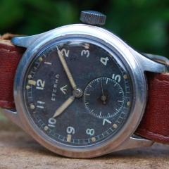
    • Here are the photos of the mystery watch. Grateful for any help with identifying it. Thanks everyone. Your knowledge is invaluable 
    • Checked already it is 1.9mm. Meanwhile I came also to the same conclusion that the MS I am looking for is numbered as 2230 which is 2.05 mm in height (and made in different strengths), that's the reason why I double checked.. maybe it is the correct height. The barrel lid is actually not the press in type but the one which sits on the top so maybe the 2.05 what we are looking for. I put the barrel arbor and lid together and I think the gap and the 1.9mm adds together to 2.05mm:   2230 here which is for size 0s & 3/0s:  https://pocketwatchdatabase.com/reference/mainsprings  
    • That would actually be very clever and it would probably wash off the lubrication. You're supposed to apply it to clean parts then let it run a little bit and then apply the lubrication. Software-based timing solutions is a interesting term because you do require some hardware. As the world of timing machines have gotten more complicated even things like which he timing machines that might appear to be a physical timing machine are not they're basically a PC running well the machine at work is running Windows CE. Which from time to time has to be rebooted because it decides it doesn't want to work. Currently witschi decided that probably the intelligent move that they really not in the manufacturing and now they microphones with USB typically so expensive microphone because they have all sorts of nifty electronics buried in the thing and software in use apply the PC. Then as this image was convenient here's an example of what I was talking about how other methods of showing things can show things.This image was convenient I have others that are way more dramatic but you can see the effect of the gear train having some power fluctuations not bad though for 17 size vintage Elgin watch. In any case you can see the effect of the power and the gear train producing Uneven power and yes all gear trains are going to do this to a certain degree it's just the way they work and then we can see the output changes a little bit but not enough to be really concerned about for watch like this. Then the lift angle is probably not correct for this particular watch either So basically for any software you get your going to need a microphone and that will require some electronics fortunately some other people making software grasp this and they will supply a microphone.   Here's a program that I've used. This is their US websites I do find websites for timing machine software or even timing machines quite interesting because apparently whoever comes here is supposed to grasp everything about whatever it is there purchasing where typically they may not especially if the software has enhanced features. https://www.etimer.net/ Then we have PCTM As you see highly recommended by others on the group. I think you going to need the enhanced version which you have to pay for I only have the free version. Frank's website is a bit hard to find and does seem to lack pretty pictures and descriptions of how the software works although he does of a PDF that explains this if you could find his website that is.    
    • So are you saying the existing spring is 1.65mm high? If that's the case then it's the wrong spring to start with. You also need to check the barrel depth again to confirm this is correct.
×
×
  • Create New...