

-
Recently Browsing
- No registered users viewing this page.
-
Topics
-
-
Posts
-
 Or, if you have a staking set or jewelling too, just use one of the stumps. You can choose a fine tip to fit inside a jewel if necessary.
 -
.thumb.jpg.cb17a66989f1e796fd4217db2e9ca9df.jpg) Good morning, To be honest, I'm not sure I trust my own logic anymore 😅. But here's a picture of my own (failed!) attempt to install a new rotor axle. I punched way to hard and even split the metal of the rotor. My thinking was that, in my case, the axle sits "deeper" in the rotor and hence the rotor would be closer to the movement plates. Vice versa, I was thinking that a very light punch could cause the rotor to sit rather high. But not sure that makes sense because in both cases, the flat part of the axle and the rotor align equally. Sorry, but is he saying that the outside of the caseback has been polished to such an extent that the inside of the caseback has deformed/sunk??? That sounds crazy to me because those casebacks are thick! Can you see any signs of that on the inside of the caseback? Have you tried screwing in the caseback a litte bit more or less so that the supposedly "sunk" part of the caseback would move from 9 o'clock to e.g. 6/7 or 11/12 o'clock? If the caseback is truly deformed, maybe it could be punched/pressed back into shape (e.g. with glass/caseback closing press). I agree with your choice. But yea, Rolex makes it VERY hard for independent watchmakers to do a perfect job because we can't get (original) parts easily. Your pictures aren't too bad. But still impossible to see if the rotor isn't perfectly flat. You'd have to look at it with your loupe, from the side (like the pictures), and turn the rotor to see if the gaps (with the automatic bridge plates) increase/decrease. Finally... how is the up/down play of the rotor? To test, take a toothpick/pegwood and press on the small triangular side of the rotor next to the axle (NOT the big side where the weight is. But the opposite side.). Does that lift up the weight-side of the rotor? There can be some play, but it should really be minimal. If there's too much play, a new spring clip is the first thing to do. After that, one could play around with the jewels. This is too much:
Good morning, To be honest, I'm not sure I trust my own logic anymore 😅. But here's a picture of my own (failed!) attempt to install a new rotor axle. I punched way to hard and even split the metal of the rotor. My thinking was that, in my case, the axle sits "deeper" in the rotor and hence the rotor would be closer to the movement plates. Vice versa, I was thinking that a very light punch could cause the rotor to sit rather high. But not sure that makes sense because in both cases, the flat part of the axle and the rotor align equally. Sorry, but is he saying that the outside of the caseback has been polished to such an extent that the inside of the caseback has deformed/sunk??? That sounds crazy to me because those casebacks are thick! Can you see any signs of that on the inside of the caseback? Have you tried screwing in the caseback a litte bit more or less so that the supposedly "sunk" part of the caseback would move from 9 o'clock to e.g. 6/7 or 11/12 o'clock? If the caseback is truly deformed, maybe it could be punched/pressed back into shape (e.g. with glass/caseback closing press). I agree with your choice. But yea, Rolex makes it VERY hard for independent watchmakers to do a perfect job because we can't get (original) parts easily. Your pictures aren't too bad. But still impossible to see if the rotor isn't perfectly flat. You'd have to look at it with your loupe, from the side (like the pictures), and turn the rotor to see if the gaps (with the automatic bridge plates) increase/decrease. Finally... how is the up/down play of the rotor? To test, take a toothpick/pegwood and press on the small triangular side of the rotor next to the axle (NOT the big side where the weight is. But the opposite side.). Does that lift up the weight-side of the rotor? There can be some play, but it should really be minimal. If there's too much play, a new spring clip is the first thing to do. After that, one could play around with the jewels. This is too much: -
 could start a new sub-brand: Bergeon-Pro Worked for Apple phones! Ah they already beat me to it:
 -
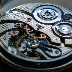
 Hello, those RR pocket watches are nice watches, there are still parts around...
 -
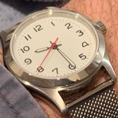
The hairspring looks to be in good condition from the photographs, it is natural that the balance will perform slightly differently in different orientations. Assuming there is no damage, the difference may be caused by the balance moving relative to the jewels, not the hairspring itself. So too much space between the jewels (endshake) and the difference will be greater, if one jewel is oiled and the other not, then again a lower amplitude in one position than the other....and so on. If the difference is reasonable (like your 13 seconds) the the best thing to do is to make one position slightly fast (+7 seconds, and the other position slow -7 seconds) then this averaging of the error will make for a more accurate watch in use. If the difference was much greater eg 100 seconds, then you would need to troubleshoot the problem. Additionally, you need to let the watch run-in for 24-48 hours after a service to allow the new oils to work their way in to all the jewels and pivots etc before you make a 'real' timegrapher test, otherwise you can get strange results. For example the oil in the top shock setting may be evenly spread, but not (yet) in the bottom setting = high difference.... after 24 hours this oil will probably have sorted itself out and the difference may be much better.
-


Recommended Posts
Join the conversation
You can post now and register later. If you have an account, sign in now to post with your account.
Note: Your post will require moderator approval before it will be visible.