Jump to content

How is this filing rest used?


Recommended Posts

There were couple of mysterious bits floating around in the bottom of a watchmaker's lathe box whose function escaped me. One was obviously a file rest, but I couldn't see any way of mounting it to anything. The other was just some random seeming bits of shiny metal:

PXL_20231124_162649012.thumb.jpg.32911e70e40d7bd5455ffe58ac773e68.jpg

The other day I was looking for some images of filing rests (the conventional double-roller sort) and google found me a post on Reddit where someone was asking 'what are these tools'. Among them was this image:

4mdqx4jsvbv012.thumb.jpg.4ddf594ba21986f638485cff55c798f0.jpg

The person who responded said "It's a filing rest". I rushed to put my bits together and what do you know:

PXL_20231124_162846951_MP.thumb.jpg.7a7661ab536136853616875fe9b0dc32.jpg

My question is, how is this mounted to anything on the lathe? The bottom 'cup' bit acts as a screw clamp, I think, but to what? The screw isn't long enough for it to open very wide. There's a couple of purposeful-looking 'nicks' you can see in the photo. I can find no other photos like it on google and it's not in Britten or any of the lathe books I have. Any ideas how it's used?

Link to comment
Share on other sites

4 minutes ago, ic0n said:

Come on - have a guess! Someone must have a clue?!

Ask me about the screw lantern in the top left of the second picture 😅

6 minutes ago, ic0n said:

Come on - have a guess! Someone must have a clue?!

You can see the 2 rollers that the file rests on, what you dont see is the mount on the lathe.

Link to comment
Share on other sites

I am thinking that you are correct that the part you said looks like a cup bit and the other part with the cutouts attaches to some upright bolt on the toolpost of a watchmakers lathe.

 I just had a quick look online and I think you would want to mount it on a T bolt attached to something like the crosslide on this lathe. 
https://www.ebay.com.au/itm/125097830836?chn=ps&norover=1&mkevt=1&mkrid=705-159824-816807-4&mkcid=2&mkscid=101&itemid=125097830836&targetid=4585444532064602&device=m&mktype=&googleloc=&poi=&campaignid=412352395&mkgroupid=1309518645581565&rlsatarget=pla-4585444532064602&abcId=9300543&merchantid=136820&msclkid=e807fc1532a01c357b9099716690733c
This is total guess though.

 Is it possible that even though it is called a filling rest that it is possibly used with a Jacot tool and a burnisher?

Edited by Michael1962
Link to comment
Share on other sites

1 hour ago, Michael1962 said:

I am thinking that you are correct that the part you said looks like a cup bit and the other part with the cutouts attaches to some upright bolt on the toolpost of a watchmakers lathe.

 I just had a quick look online and I think you would want to mount it on a T bolt attached to something like the crosslide on this lathe. 
https://www.ebay.com.au/itm/125097830836?chn=ps&norover=1&mkevt=1&mkrid=705-159824-816807-4&mkcid=2&mkscid=101&itemid=125097830836&targetid=4585444532064602&device=m&mktype=&googleloc=&poi=&campaignid=412352395&mkgroupid=1309518645581565&rlsatarget=pla-4585444532064602&abcId=9300543&merchantid=136820&msclkid=e807fc1532a01c357b9099716690733c
This is total guess though.

 Is it possible that even though it is called a filling rest that it is possibly used with a Jacot tool and a burnisher?

I'm not sure you would use it with a cross slide, what you are looking at in the link is a vertical tool post to hold cutters. I dont see why it cant be attached from the side locking nut through a hole in a flat post. There's a part that we are not seeing.

Link to comment
Share on other sites

1 hour ago, ic0n said:

This is tool fully dismantled:

PXL_20231127_170210393.thumb.jpg.c79e70bb453e3eb37d5230c81c719c20.jpg


It's only a single roller. It seems strange that the other one out there in Internet-land had exactly the same parts?

Ah that makes more sense, i thought this ( see the picture below ) was another roller. I've seen them with 2. That part just swaps out for the t-rest then  doesn't it and drops onto a rod thats in place of the rest ?

Screenshot_20231127-201004_Samsung Internet.jpg

2 hours ago, ic0n said:

This is tool fully dismantled:

PXL_20231127_170210393.thumb.jpg.c79e70bb453e3eb37d5230c81c719c20.jpg


It's only a single roller. It seems strange that the other one out there in Internet-land had exactly the same parts?

Seems a lot of kafuffle when a post on the bottom of the rest will do. What does your lathe setup look like ?

20231127_202845.jpg

Link to comment
Share on other sites

My lathe is a 6mm Lorch. I actually do have a couple of filing rest options, but I'm just curious about this widget!

PXL_20231128_133947637.thumb.jpg.3395b369c10c42515f94b8407c196ca8.jpg

PXL_20231128_133817692_MP.thumb.jpg.5f38ed41645b31ea6acb8a4b5c771b11.jpg


I tried the idea of using the tool rest, but it's too tall:

PXL_20231128_133900699_MP.thumb.jpg.98e4f7a92597a9831e8c444a606f68d4.jpg


Anything on the cross-slide would definitely be too tall:

PXL_20231128_134116727_MP.thumb.jpg.7687f1810b44cf52f9467d9a586a5007.jpg


I have a few other bits whose function I'm puzzled about, but we'll come to those later!

PXL_20231128_134236854_MP.thumb.jpg.ff758e668ad4ee1defac89b34fe8c0b8.jpg

PXL_20231128_134206382.thumb.jpg.36032ad7914898932339418115345007.jpg

Link to comment
Share on other sites

1 hour ago, ic0n said:

My lathe is a 6mm Lorch. I actually do have a couple of filing rest options, but I'm just curious about this widget!

PXL_20231128_133947637.thumb.jpg.3395b369c10c42515f94b8407c196ca8.jpg

PXL_20231128_133817692_MP.thumb.jpg.5f38ed41645b31ea6acb8a4b5c771b11.jpg


I tried the idea of using the tool rest, but it's too tall:

PXL_20231128_133900699_MP.thumb.jpg.98e4f7a92597a9831e8c444a606f68d4.jpg


Anything on the cross-slide would definitely be too tall:

PXL_20231128_134116727_MP.thumb.jpg.7687f1810b44cf52f9467d9a586a5007.jpg


I have a few other bits whose function I'm puzzled about, but we'll come to those later!

PXL_20231128_134236854_MP.thumb.jpg.ff758e668ad4ee1defac89b34fe8c0b8.jpg

PXL_20231128_134206382.thumb.jpg.36032ad7914898932339418115345007.jpg

It looks like it needs to be on the other side of the post and the roller should be pointing  upwards on its frame. If its still too high maybe it was meant for a bigger clearance headstock ?

Link to comment
Share on other sites

I think Nickelsilver and Neverenoughwatches are saying roughly the same thing and I see the logic. The only thing that gives me pause is that mechanically, having the roller pivoted at the end would be an odd choice. Any excess pressure when you were filing and the damned thing would slip.

Well now I feel silly:

PXL_20231128_163205591.thumb.jpg.4b49ff313c727446d296ec976510e41f.jpg

The 'system' merged my two replies - it made more sense when they were separate!

Link to comment
Share on other sites

10 hours ago, Michael1962 said:

Try loosening the horizontal clamp and rotating the vertical clamp forward until the top of the roller is on the centreline of the lathe. If you can’t get it there, I would suggest that this rest is for a lathe with a higher centreline. 

Hi Michael - see my picture in the post above yours - it turns out to be a graver sharpening jig, not a roller file rest after all! And it does a very fine job of that.

Link to comment
Share on other sites

Join the conversation

You can post now and register later. If you have an account, sign in now to post with your account.
Note: Your post will require moderator approval before it will be visible.

Guest
Reply to this topic...

×   Pasted as rich text.   Restore formatting

  Only 75 emoji are allowed.

×   Your link has been automatically embedded.   Display as a link instead

×   Your previous content has been restored.   Clear editor

×   You cannot paste images directly. Upload or insert images from URL.


  • Recently Browsing

    • No registered users viewing this page.
  • Topics

  • Posts

    • Hello WRT members I started a project 4years ago printing straps for seiko model 5M42-0E69. This because the strap wasn’t produced anymore and i needed a strap for my father’s watch that come to my possession. I found someone who was willing to make a computer drawing and than he started printing and worked out well. To build up the metal caps you need to have some patience but it worked. 
    • Hello a nd welcome ro the forum.      Enjoy.
    • I went with GBP as you guys started it off and $4.04 adjusted for inflation.
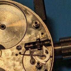
    • Great help for me - thank you all. If the hairspring has been shortened, it must have have even tighter coils than it does now and they all look utterly concentric but nevertheless I'm not leaning further towards that explanation. For me, vibrating a new hairspring would be far from easy - I wouldn't know where to start.And if a new contrate wheel has been cut and mounted, it's been done very skilfully, leaving no obvious telltale signs. Cutting and crossing out contrate wheels takes skill, too, so a bit of a last resort. and why would the he have cut 70 teeth if the existing one had 75. The platform certainly looks original to the clock but I cannot rule out the possibility that it has been taken from a similar period one (with a different tooth count). It was produced by Soldano (who supplied Dent) and the movement is by Hollingue Freres (who worked for Drocourt) so it's a nice small one (not a miniature) but I have to say that it does look like it has been worked on by someone with a hammer and centre punch instead of a bushing tool. The history isn't know - the current owner has never seen it working. I completely dismantled it again at the weekend to make the tooth count but when I've figured it out, I'll take some photos. But for now, I think I've reached the end of the line.
    • Thank you for your introduction and welcome to this friendly forum. We all look forward to your contributions and continued involvement.  You might find this helpful. 704789946_TZIllustratedGlossary(2).pdf
×
×
  • Create New...