
Movement holder made with 3D printer


-
Recently Browsing
- No registered users viewing this page.
-
Topics
-
-
Posts
-
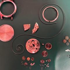
.thumb.jpg.cb17a66989f1e796fd4217db2e9ca9df.jpg) Hi @Roll1ex, welcome to the forum. It's considered good practice to introduce yourself to the forum in this thread: https://www.watchrepairtalk.com/forum/23-introduce-yourself-here/ But no worries. I don't have the spec sheet for the 15xx movements, but when I look at the 31xx information, it stands out that the endshake of the rotor should be between 0.01 and 0.03mm. That is LESS than the pallet fork and the lowest of all endshakes in the movement. Not exactly sure what you mean by that. The rotor itself is a unique part which doesn't have different heights. If you mean the height at which it is installed vis-a-vis the automatic bridge, then yes, that can be adjusted a bit via the two jewels that hold the rotor axle. Height differences vis-a-vis the bridge can also be caused by the strength with which the new axle is hammered/riveted into the rotor. And yes, that can be compensated a bit via the jewels. This would probably indicate that the axle isn't perfectly perpendicular to the rotor. That could explain why the weight is closer to the rest of the movement at 9 o'clock -- it would then be furthest at 3 o'clock. That would be bad news. A new axle should then be installed... and properly this time. As I wrote already, there is margin for adjustment via the jewels. As for the spring clip, the 15xx movements only seems to have one spring clip thickness (part 7911 - https://www.cousinsuk.com/PDF/categories/2878_Rolex 1530 Pages 6-10.pdf). The later 31xx movments have several versions with different thicknesses. But there is a good chance that the clip is worn (=thinner than it should) and should then be replaced. But, in conclusion, if the rotor hits the caseback in one particular postion, then my first suspicion is that the axle wasn't punched in at a perfect 90° angle. That must first be re-done correctly. No other fixes will be solving that problem. Furthermore, if the rotor "dings" against the caseback when the watch is shaken (but not in other situations), then there is likely also an issue of endshake (more an issue of the jewels) or lateral play (more likely the sping clip). PS: by whom? Independent or RSC?
Hi @Roll1ex, welcome to the forum. It's considered good practice to introduce yourself to the forum in this thread: https://www.watchrepairtalk.com/forum/23-introduce-yourself-here/ But no worries. I don't have the spec sheet for the 15xx movements, but when I look at the 31xx information, it stands out that the endshake of the rotor should be between 0.01 and 0.03mm. That is LESS than the pallet fork and the lowest of all endshakes in the movement. Not exactly sure what you mean by that. The rotor itself is a unique part which doesn't have different heights. If you mean the height at which it is installed vis-a-vis the automatic bridge, then yes, that can be adjusted a bit via the two jewels that hold the rotor axle. Height differences vis-a-vis the bridge can also be caused by the strength with which the new axle is hammered/riveted into the rotor. And yes, that can be compensated a bit via the jewels. This would probably indicate that the axle isn't perfectly perpendicular to the rotor. That could explain why the weight is closer to the rest of the movement at 9 o'clock -- it would then be furthest at 3 o'clock. That would be bad news. A new axle should then be installed... and properly this time. As I wrote already, there is margin for adjustment via the jewels. As for the spring clip, the 15xx movements only seems to have one spring clip thickness (part 7911 - https://www.cousinsuk.com/PDF/categories/2878_Rolex 1530 Pages 6-10.pdf). The later 31xx movments have several versions with different thicknesses. But there is a good chance that the clip is worn (=thinner than it should) and should then be replaced. But, in conclusion, if the rotor hits the caseback in one particular postion, then my first suspicion is that the axle wasn't punched in at a perfect 90° angle. That must first be re-done correctly. No other fixes will be solving that problem. Furthermore, if the rotor "dings" against the caseback when the watch is shaken (but not in other situations), then there is likely also an issue of endshake (more an issue of the jewels) or lateral play (more likely the sping clip). PS: by whom? Independent or RSC? -

By Neverenoughwatches · Posted
Morning OH, absolutely not, that has never been the intention, there does seem to be a lot of emphasis placed on that point. Its only a contact storage location. Honestly OH , i cant get my head around why anyone wants to think why members would be pulled away from a forum that works so well. Your fear of losing the forum OH is exactly the same as everyone else's. Hopefully it will wont happen for a very long time, but not having a back up would mean that everything would be lost if it ever came to that. Scott has set that up for anyone that wants a failsafe, if they are not comfortable with it then of course they dont need to participate. Its entirely of their free will. -
 Wow what a difference. As long as you are happy with the set up and it works for you it makes no odds. The belt is in line with the pulleys so no problem there. No questions are silly on this site.
 -

By RichardHarris123 · Posted
Hello and welcome from Leeds, (Rothwell). Originally from Allerton, Bradford. -
What is this going to be used for. I don't want to be part of anything that will drive traffic away from here.
-


Recommended Posts
Join the conversation
You can post now and register later. If you have an account, sign in now to post with your account.
Note: Your post will require moderator approval before it will be visible.