
-
Recently Browsing
- No registered users viewing this page.
-
Topics
-
-
Posts
-
 Hello all, just disassembling to service, but I can’t figure out the working of the calendar work…it’s not operational the jumper and spring are ok, but the operation of the driving wheel has me at a loss. I can’t see a cam to drive anything. Is something damaged or missing? Help please!
 -
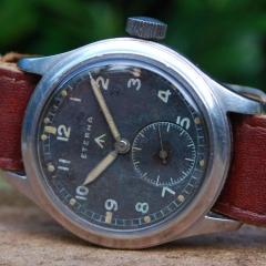
.thumb.jpg.19a9c4ff164d78d516aa9f05a063752b.jpg) Believe the relume (not a fan) was done a long time after the damage.
Believe the relume (not a fan) was done a long time after the damage. -
 I can only think of some chemical reaction to reluming
 -

By nickelsilver · Posted
I have a little milling attachment for my WW lathe, but very rarely use it and not for wheel and pinion cutting. For that I use a small Sixis 101 milling machine. I normally do direct dividing, but sometimes have to do an odd count and use the universal index which also fits on the Sixis. Back in the day when I didn't have a mill, I would cut gearing on my Schaublin 102. It has a universal dividing attachment which fits the back of the spindle. Both it and the one for the Sixis are 60:1 ratio, and with the set of 4 index plates I can do almost any division. When I've had to do a strange high count prime number, I print a disc with the needed division and just place the plunger on the dot. Any position error is reduced by a factor of 60 so still plenty accurate. The machines are a mess in the pics as I'm in the process of making a batch of barrels for a wristwatch 🙃. This is the Sixis. The head can also be placed vertically, as can the dividing spindle. Dividing plates. The smaller ones fit another dividing spindle. Universal divider for the Sixis. I put it together with parts from an odd Sixis spindle that takes w20 collets, like the Schaublin 102, and a dividing attachment from a Schaublin mill. The dividing attachment for the 102. The gear fits in place of the handwheel at the back of the headstock. And the little milling attachment for the WW lathe. I just set it on the slide rest to illustrate the size, you can see from the dust on it it really doesn't get used much. I think only when I change bearing in the head, to kiss the collet head seat (grinding wheel still in the milling attachment). -
 I read a lot about the quality (or lack thereof) of Seiko's 4R, 6R, 8L movements...or more specifically the lack of regulation from the factory. Especially when compared to similar priced manufactures using SW200's or ETA's. I thought I'd ask those more in the know, do the 4R's and 6R's deserve their bad reputation, is it fairly easy for someone with minimal skills (or better yet a trained watch mechanic) to dial in these movements to a more acceptable performance. For background I spent more on a 1861 Speedy years ago, expecting that the advertised 0-15s/d would probably perform more like 5-7s/d. In reality it's been closed to 2-4s/d.
-


Recommended Posts
Join the conversation
You can post now and register later. If you have an account, sign in now to post with your account.
Note: Your post will require moderator approval before it will be visible.